The selection of an appropriate engine is critical to the performance of an aircraft or any other vehicle. However, aircraft have tighter constraints. Thus, an appropriate engine that best suits the given mission requirements must be selected. Constraints on engine selection often include size, weight, power, and specific fuel consumption. For general aviation (GA) aircraft flying at low altitudes and at low Mach numbers, reciprocating engines have proved to be the best propulsion options. Of course, electric engines are also making significant progress in small aircraft and Uninhabited Aerial Vehicle (UAV) applications. For airplanes flying at speeds up to about 500 knots and a service ceiling of about 40, 000 feet, turboprops serve the best. Beyond these limits, turbojets and turbofans are the most appropriate power plants.
The piston engine is an integral part of the general aviation aircraft design. The importance of the piston engine in aviation can been seen by looking at all of the small civilian aircraft that are completely reliant on piston engines as their means of propulsion. The majority of small UAVs and radio-controlled aircraft are also piston engine powered.
In this chapter; we briefly cover engines other than gas turbine engines. We concentrate primarily on reciprocating engines and their systems, due to their extensive application on GA aircraft and UAVs. The material is presented very briefly and, in some cases, in bullet form due to space limitations. However, an extensive bibliography is included at the end of the chapter for further reference.
5.2 Cycle Analysis
5.2.1 Otto Cycle
The Otto Cycle is an air standard cycle that approximates the operation of spark-ignition engines. The T–s and P–V diagrams of this cycle are shown in Figure 5.1. The ideal Otto Cycle operates on the constant-volume principle. It consists of an isentropic compression, a constant-volume heat addition, an isentropic expansion, and a constant-volume heat rejection process as shown in the above figure. It can be shown that the ideal thermal efficiency of the cycle, ηth, = 1 – = 1 – = 1 – , in which CR is the compression ratio (defined in Section 5.3). For derivation of the above equation, references 6to 15may be consulted. From this equation, it is clear that the cycle thermal efficiency increases with increased compression ratio. But in real engine cycles, fuel octane number has to be increased as well to prevent engine knocks (pre-ignition and detonation). Currently, only 100LL (low lead) avgas (aviation gasoline) is available at the airports. This fuel limits the compression ratio of aircraft engines and prevents a high level of supercharging. The thermal efficiency of air-cooled aircraft engines is about 30%.
The P–V diagram of an actual four-stroke cycle engine is shown in Figure 5.3.
FIGURE 5.3The P–V diagram of a 4-stroke cycle engine
In a four-stroke engine the valve timing is:
Intake valve opens before the top dead center of the exhaust stroke. The exhaust gases rushing out of the cylinder create suction and help in admitting more fresh charge into the cylinder. This improves the engine’s volumetric efficiency.
Intake valve closes after bottom dead center of the compression stroke. This is to take advantage of the inertia of the incoming charge. It improves the volumetric efficiency of the engine.
Exhaust valve opens before bottom dead center of the power stroke. This prevents overheating of the cylinders. The exhaust gases are forced out of the cylinder under their own pressure.
Exhaust valve closes after top dead center of the intake stroke. This is to take advantage of the inertia of the exhaust gases to force more exhaust gases out and also, by creating suction in the cylinders, to help bring more fresh charge in the cylinders. This improves the volumetric efficiency of the engine.
The spark plug generates a hot spark before top dead center (BTDC) of the compression stroke. The period of time (the angular rotation of the crankshaft) during which both valves are open is called valve overlap.
5.2.2.2 Diesel Engines
An increasingly popular power plant for general aviation (GA) aircraft and uninhabited air vehicles (UAVs) is the diesel engine. While still not very common, advances in diesel engine research and development have led to more of these engines being available and even certified by the U.S. Federal Aviation Administration (FAA).
Diesel engines are very attractive power plants due to their low specific fuel consumption (sfc) and their ability to use a variety of available low-cost fuels. The increase in price of avgas and its limited availability, specifically at higher octane number range has led to the additional research and increased popularity of diesel engines in aircraft application. The ability of diesel engines to run on jet fuel makes them ideal for both civilian and military applications.
Many years ago, several diesel aircraft engines built by Guiberson, Packard, Rolls-Royce, Clerget, Fiat and other manufacturers powered older aircraft. The very successful Junkers “Jumo 205” supercharged two-stroke diesel engine was used in scheduled transatlantic service between Europe and South America. It had a cruise bsfc (brake-specific fuel consumption) of 0.356 lb/bhp-hr, delivered full sea-level power up to 40, 000 feet and powered aircraft flying at 50, 000 feet. It was a direct drive, air-cooled, two-stroke cycle diesel with four cylinders per row. It featured two stages of supercharging and intercooling.
Although still not widespread, there are several certified and uncertified diesel engines in aviation use. Current diesel aircraft engines are comparable in size and power to the typical Continental or Lycoming engines that are common in the market. The power output ranges from 100 to 400 hp. The specific fuel consumption of these engines is as much as 0.1 lb/hp-hr, less than most spark-ignition engines.
Most of the engine applications are modifications to existing production aircraft and homebuilt aircraft. Such aircraft include the Cessna 172 and the Piper PA-28 line, of which many have been modified with Thielert Centurion brand engines. These aircraft require an STC (supplemental type certificate) to be allowed to fly. The integration of a Thielert Centurion engine on a UAV is shown in Figure 5.4. Several aircraft companies that see the advantages of diesel engines offer or are planning to offer aircraft with a diesel engine option too. Such companies include Cessna, Maule (U.S.A.), Diamond (Austria), and Socata.
FIGURE 5.4Thielert aircraft diesel engine installed on Meridian UAV
Advantages of diesel engines
Desirable fuel type: low flammability and worldwide availability of Jet-A or diesel fuel is valued in all applications.
Fuel efficiency: the bsfc (brake-specific fuel consumption) of diesel engines is typically lower than 0.4 lb/hp/hr versus current avgas-powered aviation engine with a bsfc of 0.59 lb/hp/hr at 75% and above. For large two-stroke marine diesels, the sfc could be as low as 0.26!!).
Lower fuel cost and higher fuel availability: 20–30% more range per gallon. Also, cost per gallon of Jet-A is less than 100LL aviation fuel in the U.S.A. The price differential is much greater in Europe. No fuel availability problem worldwide.
Single-lever power operation: no mixture, no alternate air, no auxiliary fuel pump, no magneto switches, no mandatory temperature, boost or power restrictions.
Electromagnetic noise elimination: absence of an ignition system reduces interference with navigational and communication systems. For military applications, this is desirable for tactical reasons.
Durability: inherent in diesels because diesel and jet fuels provide more lubricity and because no electrical system (magnetos or electronic ignition) is required.
Less toxic emissions: diesel and jet fuels contain no toxic substances such as lead, benzene or scavengers.
Dramatically reduced fire hazard: diesel fuels have much lower flammability. Exhaust manifold temperature is about few hundred degrees lower than gasoline engines.
Good reliability and low maintenance cost: no carburetor icing, no magneto or spark-plug problems, and no vapor lock.
Disadvantages of diesel engines
Unreliable starting at low temperatures
Higher weight
Higher operating temperature.
Some modern diesel engines are shown in Table 5.1.
The events that occur during one cycle of operation of two-stroke cycle engines (Figure 5.5) are:
intake of the charge to the crankcase
transfer of the charge from crankcase to the combustion cylinder
compression
ignition
power
exhaust.
FIGURE 5.5Operation of a two-stroke engine: (a) compression, ignition, and power events; (b) exhaust and intake events.
Advantages
Mechanically simpler: fewer moving parts
Improved reliability and durability: the two-stroke piston-ported design reduces the parts count by eliminating valves, valve train and cam shaft and therefore have no valve problems
Weight reduction
Reduction of frontal area: by elimination of overhead valve mechanism
Smoothness of operation: a two-stroke has one power stroke per cylinder per revolution.
Very low vibration level: Torque vibration is minimal due to one power pulse per cylinder per revolution.
Disadvantages
Less efficient
Some of the fuel–air mixture is diluted with burned gases
Some of the fresh fuel–air charge is discharged through the exhaust port
More difficult to lubricate
More difficult to cool.
Integration of a Desert model DA-150, two-stroke cycle engine in a UAV is shown in Figure 5.6.
FIGURE 5.6Desert model DA-150, 2-stroke cycle engine installed on a UAV
5.2.2.4 Rotary (Wankel) Engines
In Wankel engines, the four strokes of a typical Otto Cycle engine are arranged sequentially around the rotating rotor, unlike the piston of reciprocating engine. In the basic single-rotor Wankel engine, a single oval (technically an epitrochoid) housing surrounds a three-sided rotor (a Reuleaux triangle), which turns and moves within the housing. The sides of the rotor seal against the sides of the housing and the corners of the rotor seal against the inner periphery of the housing, dividing it into three combustion chambers. A sketch of the Wankel engine is shown in Figure 5.7.
As the rotor turns, its motion and shape and the shape of the housing cause each side of the rotor to get closer and farther from the wall of the housing, compressing and expanding the charge in the combustion chamber similar to the “strokes” of a reciprocating engine. However, whereas a normal four-stroke cycle engine produces one combustion stroke per cylinder for every two revolutions (that is, one half power stroke per revolution per cylinder), each combustion chamber of each rotor in the Wankel engine generates one combustion “stroke” per revolution (that is, three power strokes per one rotor revolution).
Since the Wankel output shaft is geared to spin at three times the rotor speed, this becomes one combustion “stroke” per output shaft revolution per rotor, twice as many as the four-stroke piston engine, and similar to the output of a two-stroke cycle engine. Thus, power output of a Wankel engine is generally higher than that of a four-stroke piston engine of similar engine displacement in a similar state of tune, and higher than that of a four-stroke piston engine of similar physical dimension and weight.
In the Wankel engine, a triangular rotor incorporating a central ring gear is driven around a fixed pinion within an oblong chamber. The fuel–air mixture is drawn in the intake port during this phase of the rotation.
Advantages of the Wankel (Rotary) Engine
Wankel engines have several major advantages over reciprocating piston designs, in addition to having a higher output for similar displacement and physical size. Wankel engines are considerably simpler and contain far fewer moving parts. For example, because simple ports cut into the walls of the rotor housing accomplish valving, they have no valves or complex valve trains. In addition, since the rotor is geared directly to the output shaft, there is no need for crankshaft, crankshaft balance weights, and so on. The elimination of these parts not only makes a Wankel engine much lighter (typically half that of a conventional engine with equivalent power) but also completely eliminates the reciprocating mass of a piston engine with its internal strain and inherent vibration due to repetitious acceleration and deceleration, producing not only a smoother flow of power but also the ability to produce more power by running at higher rpm.
In addition to the enhanced reliability due to the elimination of this reciprocating strain on internal parts, the construction of the engine, with an iron rotor within a housing made of aluminum, which has thermal expansion, ensures that even when grossly overheated the Wankel engine will not seize-up, as an overheated piston engine is likely to do. This has substantial benefit for aircraft use.
The simplicity of design and smaller size of the Wankel engine also allow for savings in construction costs, compared to piston engines of comparable power output.
As another advantage, the shape of the Wankel combustion chamber and the turbulence induced by the moving rotor prevent localized hot spots from forming, thereby allowing the use of fuel of very low octane number without pre-ignition or detonation.
In the United States, John Deere, Inc., had a major research effort in rotary engines in collaboration with the NASA Lewis Research Center and designed a version that was capable of using a variety of fuels without changing the engine. The design was proposed as the power source for several U.S. marine combat vehicles in the late 1980s.
Disadvantages of the Wankel (Rotary) Engine
The design of the Wankel engine requires numerous sliding seals and a housing, typically built as a sandwich of cast iron and aluminum pieces that expand and contract by different degrees when exposed to heating and cooling cycles in use. These elements led to a very high incidence of loss of sealing, both between the rotor and the housing and also between the various pieces making up the housing. Hydrocarbon emission and high sfc are another two serious drawbacks of Wankel engines. Just as the shape of the Wankel combustion chamber prevents pre-ignition; it also leads to incomplete combustion of the air–fuel charge, with the remaining unburned hydrocarbon released into the exhaust.
Another disadvantage of the Wankel engine is the difficulty of expanding the engine to more than two rotors. The complex shapes of the rotor, housing, and output shaft and the way they fit together requires that engines with more than two rotors use an output shaft made of several sections assembled during the assembly of the rest of the engine. While this technique has been used successfully in Wankel-powered racing cars, it negates a great deal of the relative simplicity and lower cost of the Wankel engine construction.
The potential drawbacks of Wankel (Rotary) engines are the only reasons for its demise in aircraft applications. However, continued engineering research on the rotary engine has resulted in performance improvements through improved seals, lean-burn combustion, fuel injection, integral electronic control, improved intake design, weight reduction, and turbocharging. This could open up the way once more for the introduction of rotary engines in aircraft applications.
Indicated Horsepower (IHP). The actual power produced in the engine cylinders. This is calculated based on the cylinder pressure, RPM, and the displacement volume.
Brake Horsepower (BHP). The power output of the engine. Brake Horsepower is also sometimes called Shaft Horsepower.
Friction Horsepower (FHP). Is the power loss due to friction, accessories, and superchargers. It is indicated horsepower minus brake horsepower.
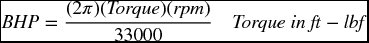
Thrust Horsepower (THP). The power delivered by the propeller. THP is calculated by BHP x Propeller efficiency.
Also, THP = (T × V∞) / 325, where V∞ is the aircraft speed in knots. The denominator will be 375 if V∞ is in mph and 550 if it is in fps. For a steady state flight, propeller thrust equals aircraft drag (T = D); therefore, if aircraft drag is known, we can solve for THP from THP = (V∞ × D) / 325.
Mean Effective Pressure, MEP, is defined as the constant pressure which would have to act upon the piston for one stroke to equal the actual work output of one complete cycle. It is actually an average pressure inside of cylinders of an internal combustion engine during the power stroke. IMEP is the indicated mean effective pressure, BMEP is the brake mean effective pressure, and FMEP is the friction mean effective pressure.
For four-stroke cycle engines: Brake horsepower, BHP =
BMEP = Brake mean effective pressure
L = Cylinder Stroke in ft.
A = Piston Head (top surface) area in in2
N = (for four-stroke cycle engines)
K = Number of cylinders
Indicated horsepower, IHP = , where IMEP is indicated mean effective pressure.
Friction horsepower, FHP = , where FMEP is friction mean effective pressure
Factors Affecting Piston Engine Power
manifold absolute pressure
RPM
fuel-to-air ratio
air density (pressure, temperature, humidity)
carburetor air intake ram pressure
exhaust back pressure
compression ratio
carburetor air temperature (CAT).
Definitions and Useful Information
Approximate value ≈ 90%
Approximate value ≈ 75% for “naturally aspirated engines”. Could be greater than 100% for supercharged engines. Volumetric efficiency decreases as RPM increases.
Approximate value ≈ 80%
Approximate value ≈ 30%
The maximum heat loss is through the exhaust gases.
Specific fuel consumption, sfc, is defined as pounds of fuel burned per horsepower per hour; lbs/bhp-hr. For FAA certified aircraft engines, brake specific fuel consumption, bsfc, ≈ 0.4 to 0.5 lbs/bhp-hr.
Engine weight to power ratio ≈ 1.0 to 2.0 lbs/bhp
For spark ignition engines, CR ≈ 7:1 to 11:1
For compression-ignition engines (diesel engines), CR ≈ 14:1 to 21:1
Heat value of aviation gasoline (avgas) ≈ 20, 000 Btu/lb.
Specific weight of avgas ≈ 6 lbs/gal.
5.4 Engine Components and Classifications
5.4.1 Engine Components
The major components of reciprocating engines (Figure 5.9) are the:
piston
cylinder
connecting rod
crankshaft.
FIGURE 5.9Main Components and terminology of piston engines
The cylinders usually have two valves, an intake valve and an exhaust valve. The majority of aircraft engine pistons are machined from aluminum alloy forgings. Some intake and exhaust valve stems are hollow and partially filled with metallic sodium. This material is used because it is an excellent heat conductor. The sodium will melt at approximately 208°F (98°C). Some valve stems have a narrow groove below the lock ring groove for the installation of safety circlets or spring rings. The circlets are designed to prevent the valves from falling into the combustion chambers if the tip should break during engine operation and on the occasion of valve disassembly and assembly.
5.4.2 Reciprocating Engine Classifications
5.4.2.1 Classification by Cylinder Arrangement
Opposed
This is the most extensively used piston type engine for general aviation aircraft. A sketch of this type of cylinder arrangement is shown in Figure 5.10.
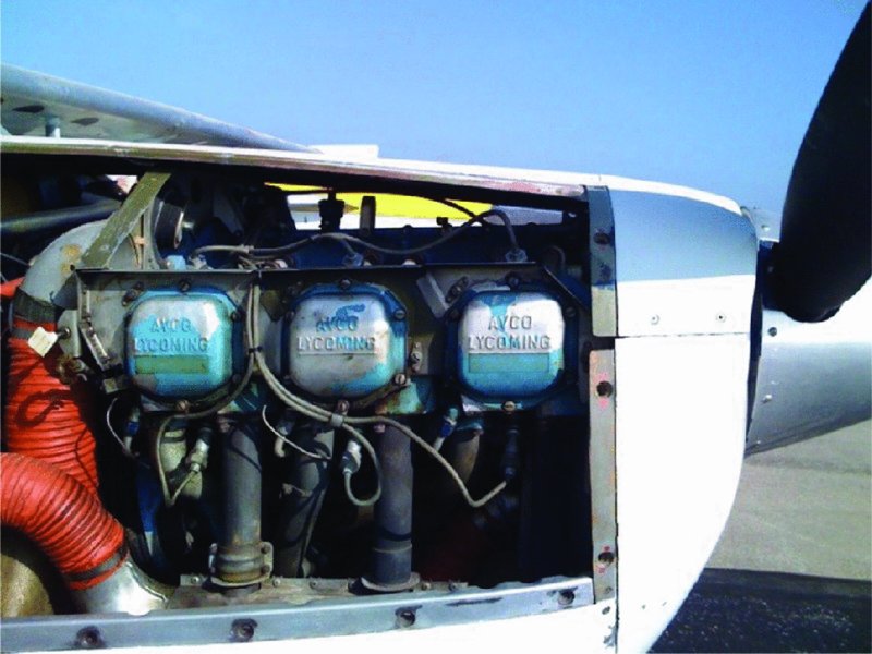
An example of this type of engine is Teledyne Continental GTSIO-520. This is a typical modern high-power, opposed-type reciprocating engine that is being extensively used on general aviation aircraft. The engine has total piston displacement of 520 cubic inches and is equipped with reduction gear, supercharger and fuel injection system. Integration of a Lycoming IO-540 opposed engine with a Cessna 182 aircraft is shown in Figure 5.11.
FIGURE 5.11Lycoming IO-540 opposed engine installation on a Cessna 182 airplane
Inline
This type of engine has been extensively used in the past for low power ranges. Limited production continues. A sketch of this type of cylinder arrangement is shown in Figure 5.12. An example of this type of aircraft engine is the M-337b, which is a six-cylinder inline engine made by LOM PRAHA that generates 173 kW of power.
This arrangement is suitable for powerful engines having more than six cylinders. A sketch of this type of cylinder arrangement is shown in Figure 5.13. An example of this type of engine is the Pratt and Whitney R-4360. This 28-cylinder radial engine, with four rows of seven cylinders in each row, has 4360 cubic inches of piston displacement. This was the largest and most powerful reciprocating engine built and used successfully in the United States.
FIGURE 5.13Single-row and double-row radial aircraft engine cylinder arrangements
Rotary–Radial
The cylinders of a rotary–radial engine spin around the crankshaft, which is mounted rigidly on the airframe. One end of each connecting rod rides in a groove in a cam that is offset from the center of the crankshaft. These engines have not been in actual production for a very long time.
5.4.2.2 Classification by Cooling Arrangement
Air cooled
Liquid cooled.
Air-Cooled Engines
Most aircraft engines operating today are of air cooled type. Cylinders of an air-cooled engine are shown in Figures 5.11 and 5.14. Air-cooled cylinders have cooling fins around them to increase their contact surface with air. Up to about 10% of the engine’s horsepower can be wasted by the cooling drag. The cooling air intake area can be 30–50% of engine frontal area. Cooling air exit should be about 30% larger. Either downdraft or cooling updraft cooling arrangements can be used. Integration of the air-cooled Lycoming O-320 engine on a Cessna 172 aircraft is shown in Figure 5.14, in which the engine cowing is removed to make the baffles and engine mount visible. The baffles guide the cooling airflow inside the engine nacelle and around the cylinders for maximum cooling effectiveness. The engine mount extends the engine forward of the firewall by about half of the engine length. In some aircraft this space is used for the battery and nose wheel steering.
FIGURE 5.14Integration of a Lycoming O-320 air-cooled engine in a Cessna 172 aircraft
Liquid-cooled engines
Liquid cooling reduces overcooling in descents from altitude. Also, reduced thermal variance in operation reduces engine component fatigue and allows tighter manufacturing tolerances, leading to increased power and fuel efficiency. Liquid-cooled engines have water passages around their crankcase and cylinders for cooling purposes. Streamlined installation would be difficult due to water hoses and radiators. The arrangement is similar to that used on most automobile engines. The Thielert Centurion diesel engine shown in Figure 5.4 is liquid cooled.
5.4.2.3 Classification by Operating Cycle
Four-stroke cycle engines
Two-stroke cycle engines.
The above cycles have been covered in Sections 5.2.2.1 and 5.2.2.3 respectively.
5.4.2.4 Classification by Ignition Type
Spark-ignition engines
Compression-ignition engines (diesel)
The ignition systems will be covered in Section 5.6.3 and diesel engines have already been covered in Section 5.2.2.2
5.5 Scaling of Aircraft Reciprocating Engines
When considering the design of a piston engine driven aircraft, a major consideration that must be accounted for is the type and size of engine used. The amount of horsepower that an engine can produce is necessary in order to provide adequate thrust for the aircraft and allow it to lift off of the ground. However, for most cases, the more horsepower that an engine can produce, the more it will weigh.
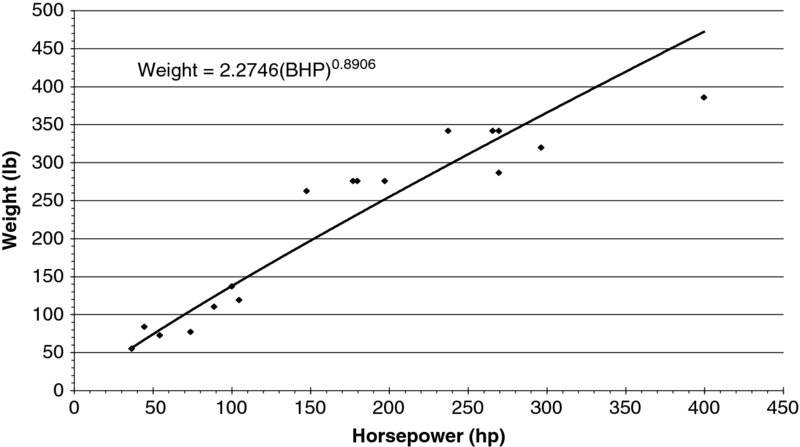
The analysis of engine data, such as bore, stroke, capacity, horsepower, weight, and specific fuel consumption, from full size engines and Remotely Controlled (RC) engines over the past decade shows in multiple trends. These trends include a linear relationship between the weight of a piston engine and the horsepower it produces. Several scaling equations have been developed for full size engines and Remotely Controlled engines with specifically defined constants “a” and “b”. The constants and equation for which they are used is:
(5.1)
“X” could be any engine characteristic, for example, weight, sfc, and so on. The analytically derived results from the current analysis based on the data of many piston engines available for aircraft can be seen in Table 5.2. Figures 5.15–5.20 show the general trends in the piston engine industry when it comes to weight and corresponding horsepower. Obviously, the more horsepower that is required to produce, the higher will be the overall weight of the engine. For more coverage of the engine scaling laws references 4 and 16 may be consulted.
FIGURE 5.15Weight versus horsepower for opposed engines
FIGURE 5.16Weight vesus horsepower for inline engines
FIGURE 5.17Weight versus horsepower for radial engines
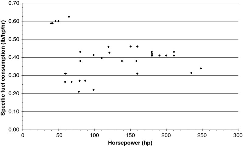
Figures 5.21 and 5.22 depict the specific fuel consumption (SFC) for some of the aircraft engines that were surveyed. This is a critical aspect of engine selection as it can determine the range and endurance of the aircraft as well as many other factors in the preliminary design stages. This also happens to be one of the least reported specifications for engine data. The graphs have been broken up into those in which the manufacturer listed the engine’s specific fuel consumption and those who listed a fuel burn rate from which an SFC was calculated. It should be noted that the calculations are not an accurate depiction of the real engines fuel consumption, which must be determined through testing. Also, there is no discernable trend for either case. The typical numbers for an SFC are 0.4 to 0.5 lb/hp/hr. However some manufacturers are beginning to breach the 0.4 value with numbers just under 0.4 lb/hp/hr. Figure 5.23 is a graph depicting the engine total displacement volume that can be expected from an aircraft piston engine of a given horsepower. It should be noted that the trend is not as clear as the models for predicting weight.
FIGURE 5.18Weight versus horsepower for V-type engines
FIGURE 5.19Weight versus horsepower for rotary engines
FIGURE 5.20Weight versus horsepower for opposed engines of less than 100 hp output
FIGURE 5.21Specific fuel consumption as posted by manufacturer
FIGURE 5.22Specific fuel consumption calculated from the given engine data
FIGURE 5.23Engine displacement volume versus horsepower for all aircraft engine types
5.5.1 Scaling of Aircraft Diesel Engines
A study of aircraft diesel engines may be found in Reference 44. This reference also contains scaling laws for predicting diesel engine size and performance parameters. All engines for which the scaling equations were given fall into the following three categories:
five or fewer cylinders
six cylinders
eight cylinders.
For each group a different set of equations should be used.
Five or fewer cylinders
The engine weight can be estimated with
(5.2)
The engine specific fuel consumption at sea level and takeoff is estimated with
(5.3)
Six cylinders
The engine weight can be estimated with
(5.4)
The engine specific fuel consumption at sea level and takeoff is estimated with
(5.5)
The engine length is estimated with
(5.6)
The engine width can be estimated with
(5.7)
The engine height can be estimate with
(5.8)
Eight cylinders
The engine weight can be estimated with
(5.9)
The engine specific fuel consumption at sea level and takeoff is estimated with:
(5.10)
The engine length is estimated with
(5.11)
The engine width can be estimated with:
(5.12)
The engine height can be estimate with:
(5.13)
5.6 Aircraft Engine Systems
5.6.1 Aviation Fuels and Engine Knock
Current aviation fuel for high compression engines is leaded and will soon be made unavailable by the U.S. Environmental Protection Agency (EPA), making these engines unusable. Many aircraft in the general aviation (GA) fleet require high octane fuels to avoid engine knock and subsequent damage during their operation. Leaded avgas, 100LL, contains tetraethyl lead (TEL) to boost octane for the safe operation of piston engine aircraft. While not all piston engine aircraft require 100LL avgas to run on, airports and the avgas market supply 100LL almost exclusively to the GA piston engine fleet because it meets the needs of the majority of the GA fleet. In 2008, the U.S. Environmental Protection Agency (EPA) lowered the National Ambient Air Quality Standards (NAAQS) for lead from 1.5 to 0.15 μg/m3 to reduce lead emission impacts on human health and the environment. During the regulatory process, the EPA identified sources of lead emissions and estimated that 50% of national emissions comes from GA aircraft due to the combustion of avgas with TEL. Initial monitoring for lead at airports indicates that the latest NAAQS may be exceeded at some airports. The FAA and industry continue to explore alternatives to avgas with TEL additive, but no alternative fuel formulation has yet been found that would meet the demands of the majority of the GA fleet for safe flight operation. In the meantime, there may be practices and procedures that can reduce the impact of lead emissions at airports. Engine malfunctions due to the wrong fuel octane number or improper mixture ratios are:
Pre-ignition (surface ignition)
This could happen if any flake of carbon or a feather-edge on a valve is heated to incandescence; it will ignite the fuel–air mixture before the correct time and the mixture will burn as the piston is moving outward. This long burning period could cause the mixture to reach its critical pressure and temperature and then results in detonation. Pre-ignition is usually due to the following:
feather-edged valves
excessive carbon formation in cylinder heads and combustion chamber
spark plugs thickly coated with carbon.
Detonation
Part of the fuel–air charge goes through normal combustion but the rest of the charge detonates. This will result in overheating and may cause major engine damage. Detonation is usually caused by using low octane number fuels in high compression or supercharged engines.
Backfiring
Is defined as burning of the fuel–air mixture in the induction system. This condition can be caused by an excessively lean mixture.
Afterfiring (torching)
Flame in the exhaust system caused by raw fuel flowing through the intake valve to the cylinder and out to the exhaust stack. Could also be due to an excessively rich mixture.
Leaded fuels ingredients
A lead compound in form of “tetraethyl lead (TEL)” is added to the fuel. The lead could burn to “lead oxide”, which is solid with a high boiling point. To prevent this a gasoline-soluble “bromine compound” is added. The mixture forms “lead bromide”, which has a much lower boiling point than “lead oxide” and, therefore, a large portion of it will be expelled from the cylinders with exhaust gases.
Dye is added to the lead and gasoline-soluble bromine compound to indicate that gasoline contains lead. The mixture of lead, bromine compound, and dye is known as an “antiknock compound”.
Avgas grades, colors, and lead contents
80: Red, max lead content 0.5 ml of tetraethyl lead (TEL) per gallon
100 LL (low lead): Blue, max lead content 2.0 ml of tetraethyl lead (TEL) per gallon
100: Green, max lead content 3.0 ml of tetraethyl lead (TEL) per gallon.
Fuel–air mixtures
The mixture ratios are the fuel-to-air ratios in terms of weight
rich best power mixture; 1:11.5 = 0.087
lean best power mixture; 1:13.5 = 0.074
best economy; 1:15 = 0.067
limits of flammability; 1:8 to 1:18.
Engine problems associated with lean mixtures
overheating
loss of power
detonation.
Note: Excessively lean mixtures could cause backfiring and possible complete engine stoppage.
Problems associated with rich mixtures
loss of power
black smoke emerging form the exhaust.
Note: Excessively rich mixtures could cause engine afterfiring (torching). Also note that rich mixtures aid in engine cooling.
5.6.2 Carburetion and Fuel Injection Systems
The aircraft engine fuel–air metering systems consist of the following types:
float type carburetors
pressure injection carburetors
fuel injection systems
full authority digital engine control (FADEC).
5.6.2.1 Float-Type Carburetors
Float-type carburetors consist of the following systems:
float mechanism and its chamber
main metering system
idling system and idle cut-off
accelerating system
mixture control system
power enrichment system (economizer system).
Main Metering System
The main metering system consists of the following components
venturi tube
main metering jet
main discharge nozzle
throttle valve
main air bleed.
Accelerating System
Between the time the idle system loses its effectiveness and the time there is sufficient airflow for the main metering system to operate, there is a tendency for the engine to develop a “flat spot” or a period of lean mixture. The same condition occurs during rapid accelerations. The accelerating system is installed to overcome this condition.
The purpose of air bleed is to keep the fuel–air mixture essentially constant as the air flow through the carburetor changes. It also aids in fuel atomization.
The economizer system enriches the mixture during high power settings to help engine cooling.
Disadvantages of Float-Type Carburetors
The main disadvantages of float type carburetors are:
carburetor icing
the fuel metering force in float-type carburetors is only due to the pressure differential between air in the float chamber and that at the main discharge nozzle and, therefore, it is low
flight attitude and disturbances can affect the float level and, therefore, fuel metering to the engine
unsuitable for aerobatics and inverted flights.
5.6.2.2 Pressure Injection Carburetors
Pressure injection carburetor design is a radical departure from float-type carburetor methodology. The float and its mechanism have been eliminated and the fuel is sprayed from the main discharge nozzle under pump pressure This drastically improves the performance of large aircraft engines. The aircraft attitude will have no effect on carburetor operation and full aerobatic capability, including inverted flight, would be feasible. The fuel discharge nozzle has been moved to downstream of the throttle valve and, therefore, throttle icing has been eliminated.
5.6.2.3 Fuel Injection Systems
In these systems, the single large main discharge nozzle that was located inside the carburetor has been replaced by multiple small discharge nozzles for each individual cylinder. There are two types of fuel injection systems:
direct fuel injection system
continuous-flow injection system.
In direct fuel injection systems, fuel is directly sprayed inside the combustion chamber of each individual cylinder. Because of the requirements of the fuel spray timing, as well as higher pump pressure requirements, this system is not used on today’s aircraft production engines.
In the continuous-flow injection systems, fuel is sprayed upstream of the intake valve, therefore eliminating the two key main disadvantages of direct fuel injection systems. This type of system is exclusively used in today’s aircraft production engines that are fuel injected.
Engines equipped with fuel injection systems do not require separate priming systems because the injection system pumps fuel directly into the intake ports of each cylinder.
5.6.2.4 Full Authority Digital Engine Control (FADEC)
As the name implies, this unit is similar to the gas turbine engine fuel controls. It measures several parameters for each individual cylinder, including manifold absolute pressure (MAP), cylinder head temperature (CHT), and exhaust gas temperature (EGT), as well as engine RPM, and adjusts the amount of fuel required for each cylinder. A pilot’s command through the throttle lever is only one input to the FADEC and that will be ignored if any of the other variables is at its maximum value. Some of the advantages of FADEC are:
demonstrated fuel saved 12–20%
approximately 5% more takeoff power
smoothest ride with less noise and vibration (subjective)
simplifies operations – single lever power control (fixed pitch propellers)
very easy restarts in-flight and hot starts on the ground
tested on max power dives with no excessive speed and no aircraft speed limits exceeded.
5.6.3 Ignition Systems
Four types of ignition system are:
battery ignition systems
high tension ignition systems
low tension ignition systems
full authority digital engine controls (FADEC)
5.6.3.1 Battery Ignition Systems
In the battery ignition system, the battery current passes through an ignition switch, the primary of an ignition coil (consists of a few turns), and contact-breaker points. The contact-breaker points convert the battery’s DC current to pulsating DC (interrupted DC). This will cause a few thousands volts to be induced in the secondary of the ignition coil, which is then distributed by the distributor among the spark plugs of the respective cylinders in the correct firing order. This system is entirely dependent on the aircraft electrical system, which could be a safety issue.
5.6.3.2 High Tension Ignition System
In this system, the high voltage is generated by the magneto and the ignition system is entirely independent of the aircraft electrical system. The aircraft battery is only used during the starting operation and is disconnected from the ignition system as soon as the engine is started. FAA certified engines are required to have two independent ignition systems and each one supplies high voltage current to one of the two spark plugs of each cylinder. The engine can operate with one system but at a lower efficiency. Both ignition systems are required to be operational before takeoff, and there is a standard procedure to conduct that test by the pilot.
5.6.3.3 Low Tension Ignition System
This system is similar to high tension ignition system, except that the magnetos generate low voltage current. The high voltage is generated by individual coils located on the top of the cylinders. The ignition harness for this system does not require heavy insulation like the high tension system, except for a very short length between the individual coils and spark plugs. This system is ideal for the aircraft flying at high altitudes.
5.6.3.4 Full Authority Digital Engine Control (FADEC)
In this system, the cross-fire ignition coils located inside the FADEC produce high voltage sparks for optimum starting and better performance. This eliminates magnetos and magneto-to-engine timing. Variable ignition timing is provided to individual cylinders for better performance.
5.6.3.5 Ignition Boosters
Ignition boosters are used to provide the high voltage to the spark plugs during starting when the magneto rpm is extremely low. Below 4 kV, the engine may not start consistently. Once the engine starts, the magnetos will kick in and the ignition boosters will be disconnected from the spark plugs.
There are four types of ignition boosters:
impulse coupling
booster coil = booster magneto
ignition vibrator = starting vibrator
solid-state magneto start booster.
From the above four boosters, the first three types are used on almost all of the existing FAA certified aircraft engines. The impulse-coupled magnetos generate about 4.8 kV and the starting vibrator systems 2.2 kV during starting. FADEC equipped engines do not require an ignition booster during starting.
Advantages of the Solid-State Magneto Start Booster
delivers over 400% more spark energy to the spark plugs (about10.2 kV).
overcomes poor engine priming
reduces electrical stress to the battery and starter
requires no maintenance.
Engine Kickback
Rotation of the crankshaft in opposite direction of normal engine operation is called engine kickback. This is caused by advance ignition during starting. Ignition should be retarded automatically by the booster to prevent kickback. FADEC will time ignition during all engine operating conditions including starting.
5.6.3.6 Spark Plugs
There are two types of spark plugs:
shielded
unshielded.
Certified aircraft engines all have shielded spark plugs. Considering that the magnetos and ignition harness are also shielded, they reduce the electromagnetic interference of the whole ignition system.
The firing end of the aircraft engine spark plugs are either of the fine-wire or massive-wire electrode type. Fine-wire electrodes are usually made of platinum or iridium alloys and the massive-wire electrode types are usually made of nickel alloys.
Hot and Cold Spark Plugs
The firing end of hot spark plugs is at a higher operating temperature than of cold spark plugs due to the long length of the insulator tip at the firing end. The hot spark plugs should only be installed on the engines that run cold, and the cold spark plugs should only be installed on the engines that run hot.
5.6.4 Lubrication Systems
The Purposes of a Lubrication System
reduce friction
to cool the engine
to clean the engine
to help piston rings in sealing the combustion chamber.
Types of Aircraft Engine Lubrication System
wet sump
dry sump
In wet sump systems, the oil reservoir is the sump located at the bottom of the engine. Lubricating oil is sucked from the sump by the oil pump, cleaned by the oil filter, cooled by the oil cooler, and then circulated through the engine. The returned oil pours by gravity to the engine sump and the process continues. All of the production piston engines today are equipped with this system.
In dry sump engines, the lubricating oil is stored in a large external tank and pumped to the engine by a pressure pump. The returned oil is collected in small sumps and returned back to the tank by a couple of scavenge pumps. An air-cooled oil cooler is located either in the pressure line or scavenge line.
Oil Coolers
Oil coolers are either air cooled or fuel cooled. Air-cooled oil coolers are similar to the coolant radiators of automobile engines and use ram air for cooling. Fuel-cooled oil coolers use fuel as the cooling agent. They are mostly used in gas turbine engines. Both have a thermostat (vernatherm) to keep the oil temperature at a constant value.
Advantages of a Fuel-Cooled Oil Cooler Compared to an Air-Cooled Oil Cooler
increased cycle thermal efficiency
less drag penalty
reduced fuel system icing
improved combustion
can have any shape and can be installed anywhere.
5.6.5 Supercharging
Supercharging and turbocharging allow maximum power from the engine at high altitudes and boost the engine power during takeoff. In a supercharged engine, a centrifugal compressor is located in the induction system and increases MAP. The compressor could be engine driven by a crankshaft through a gear train or powered by a turbine driven by the engine exhaust gases (turbocharger or turbo-supercharger). Almost all of today’s production aircraft engines that are supercharged are equipped with turbochargers. These engines are usually flat-rated (constant brake horsepower) up to a certain altitude.
When the supercharger is located between the carburetor and the cylinder intake port, it is called an internal-type supercharger. If the supercharger is located before the carburetor in the induction system, it is called an external-type supercharger. As mentioned before, turbochargers (turbo-superchargers) are designed to be externally driven devices by a turbine wheel which receives its power from the engine exhaust gases. An example of a turbocharged aircraft engine is Teledyne Continental TSIOF-550 engine, which is also fuel injected and FADEC equipped.
5.7 Electric Engines
Advantages
reduced noise
environmentally friendly
reduced maintenance
not affected by altitude
90–95% efficient versus 20–25% for aircraft reciprocating engines
for low subsonic flight, electric motors are much more efficient than internal combustion engines or jet engines and have better torque-to-weight ratios as well.
higher safety and more reliability than a reciprocating engine providing the same propulsion with fewer moving parts.
lighter weight models can be used without having the bulk of a reciprocating engine.
providing comparable aircraft performance for far lower cost than a reciprocating engines especially if the cost of fuel over a long time period is taken into account.
Disadvantages
batteries and motors have low power density
batteries are heavy and discharge fast, resulting in short flight times.
5.7.1 Electric Motors
There are two major parts: a rotor and a stator. The magnets in the rotor chase the magnets in the stator, causing rotation. The effective location of the magnets in either the rotor or the stator must be moved to keep the chase going. Magnets switch polarity by reversing the current flow. During rotation (with the motor energized), the rotor magnets are attracted to and repelled from the stator magnets in such a way to cause rotation. The commutator has segments all the way around the rotor and the stator is connected to brushes that rub against these segments to conduct the electricity.
Advantages of AC Motors
higher torque/horsepower capabilities
no permanent magnet
magnetic field strength adjustable
cost advantage.
Advantages of DC Motors
less rotor heat
wide spectrum of optimal power setting
no efficiency loss due to DC to AC conversion.
Disadvantages of AC Motors
optimal power factor: 85%
cumbersome to control.
Disadvantages of DC Motors
permanent magnet is expensive.
Note: The most commonly used motor today is actually the DC motor due to the optimal power setting variability a DC motor allows along with the benefit of not having to convert DC current into AC current (which can be expensive).
Future of Electric Motor Propelled Aircraft
We are just at the beginning of the production of the electric airplane
The electric airplane industry is clearly in its infancy, but developments are happening fast. Its future depends on the cost and energy density of batteries
The future looks bright for the environment and the development of clean-air solutions to flight
Even now, with the current cost of avgas nearing $5 per gallon, the aircraft will fly virtually for free after a couple hundred hours if you don’t factor the life of the battery.
5.7.2 Solar cells
Solar cells convert sunlight into electrical energy. The maximum efficiency achieved so far is 43%.
Negative Attributes
take up a lot of space
not efficient, absorb 10–40%
do not produce a lot of power.
Positive Attributes
abundant source of energy
clean source of power
no noise
no moving parts.
Airplane/UAV/Model aircraft applications
first applications on model airplanes was in 1957
good for small aircraft, not very useful for large aircraft
good for aircraft that requires high endurance.
5.7.3 Advanced Batteries
Li-ion Battery Basics
electrode components: lithium and carbon primarily
operate as most batteries with electrochemical cells containing cathode, anode, and separator of finely perforated plastic through which ions are allowed to pass; this arrangement is then submerged in an electrolyte solution
discharge: electrons travel from anode to cathode while chemical energy is converted to electric as ions flow within the cell
charge: an external voltage is applied to force electric current in the opposite direction and return electrical energy to chemical.
Li-ion Battery Basics (discharge of cell)
anode is comprised of a metallic solid reducing agent while the cathode is a solid oxidant
anode provides electrons to exterior circuit and Li+ ions internally
conducting electrolyte transports Li+ ions to cathode
Cathode ions are balanced with electrons from exterior circuit.
Advantages
good cycling characteristics
relatively high energy density (average 150 W-hr)
complete discharge unnecessary: no “memory”
high holding characteristics (charge lost ∼5% per month)
Disadvantages
high temperature sensitivity
poor lifespan independent of usage (∼3 years)
price (temperature monitoring system, etc.)
potentially hazardous failure characteristics
Li-ion: Aviation Battery Applications
In addition to their application in small technologies, such as cell phones, laptops, small UAVs and so on, Li-ion batteries have been integrated in large commercial aircraft.
Battery applications on large commercial aircraft are:
provide power for on-ground (engine off) maneuvering such as refueling and towing
Auxiliary Power Unit battery powers the APU in emergency conditions
main battery supplies power to systems prior to engine start
main battery also serves for redundant power to critical areas during flight.
Future Aviation Battery Demand
increasing popularity and applications for light weight vehicles and UAVs
greater focus on environmentally friendly aircraft
increasing battery reliability and cycling characteristics
significantly lighter than previous alternatives and work well in conjunction with other “green” technologies such as solar energy
large aircraft moving away from hydraulic systems and replacing with electric, leading to increased electrical capacity demand
easy to replace and service when compared with electric engines and so on.
5.7.4 Fuel cells
Fuel cells are a source of electrical energy somewhat similar to a battery. Both use chemical reactions to generate electricity instead of using moving parts. However, batteries just store energy, fuel cells produce it continuously as long as a fuel and oxidant are supplied.
Charge exchange occurs between the anode and cathode by means of the electrolyte in between. This gives off heat and water, while converting the chemical energy directly into electricity. The heat given off can also be used to enhance combined-cycle applications by creating even more electricity.
Different Types of Fuel Cells
Alkaline Fuel Cell (AFC)
Molten Carbonate Fuel Cell (MCFC)
Phosphoric Acid Fuel Cell (PAFC)
Proton Exchange Membrane Fuel Cell (PEMFC)
Solid Oxide Fuel Cell (SOFC)
direct methanol fuel cell.
First Commercially Available Fuel Cell Product
alkaline: potassium hydroxide electrolyte solution, used in space applications
molten carbonate: high temperature (600–700°C), high fuel-to-electricity conversion
oil independence: fuels used can all be obtained domestically
reliability: harder to break something with no moving parts
production: operate close to constant efficiency regardless of size or load.
Problems with Fuel Cells
fuel: hydrogen is not readily available everywhere
storage: some vehicles can make it as far as a gas operated car but most are still a work in progress
durability: fuel cell systems are currently less reliable than combustion engines
cost: vehicles with fuel cells cost more than gas running hybrid vehicles.
Aerospace Applications
alkaline fuel cells have been used for over four decades on manned spacecraft
UAVs: longer sustained flight, reduced weight, good for military where supplies are not readily accessible
Airbus and Boeing are studying the replacement of auxiliary power units with fuel cells. They would reduce aircraft weight and decrease emissions.
5.7.5 State of the Art for Electric Propulsion – Future Technology
current developments focusing on raising power density of batteries and motors
lithium–air batteries
state of the art lithium ion: 100–200 Wh/k versus kerosene: 1200 Wh/kg
Future technology (2030) for lithium–air battery is 750–2000 Wh/kg
Superconducting motors. theoretical power output of 8–25 kW/kg.
5.8 Propellers and Reduction Gears
Thrust is the aerodynamic force exerted by an aircraft to overcome drag and other forces acting to retard that aircraft’s forward motion in the air and on the ground (for example, friction).
In a propeller driven airplane, it is produced by the propeller accelerating a large mass of air rearwards. The thrust exerted is proportional to the mass and velocity of the accelerated air.
Propeller Blade Airfoils
RAF – 6 (WW1)
Clark Y
Standard NACA Sections
NACA 16 series
Supercritical airfoils
New generation propeller airfoils (e.g., Dowty ARA-D).
Definitions and Terminology
Geometric Pitch: The axial distance that the propeller will move forward for one revolution if it is moving (theoretically) through a solid object.
Effective Pitch: The axial distance that the propeller will move forward for one revolution through the air. Small blade angle results in low pitch. Large blade angle results in high pitch. Because of this, the terms propeller blade angle and pitch are used interchangeably.
Propeller slip: The difference between geometric pitch and effective pitch.
Resultant Velocity: The vector sum of the rotational speed at any blade cross-section and the forward speed of the aircraft.
Blade angle: The angle between the propeller blade chord and plane of rotation at any blade cross-section. It has is maximum value around the blade hub and decreases towards the tip of propeller blade.
Helix Angle: The angle between the resultant velocity at any blade station and the plane of rotation. It varies along the blade span.
Angle of attack: The angle between the resultant velocity and propeller blade chord at any blade cross-section. If the axial velocity is zero, the blade angle and angle of attack will be equal and propeller thrust is maximum. As airspeed increases, the angle of attack decreases, therefore the blade produces less thrust.
Advance ratio: Is the ratio of the aircraft speed divided by propeller revolutions per second times the propeller diameter (J = V∞/n.D).
Feathering: When a propeller is feathered, its blades are turned to an angle of approximately 90° to the plane of propeller rotation. It is typically used when the engine is stopped in the air to prevent windmilling and, therefore, reducing the drag, as well as further damage to the engine if the stoppage is due to the engine failure.
Reversing: The propeller blade angles move to a negative value and, consequently, generate negative thrust. This is typically used to help decelerating the aircraft during landing.
Propeller efficiency=THP/BHP
Thrust Horsepower Available (THP): This is calculated by BHP × Propeller efficiency. It can also be calculated as THP = T × V∞/325, where T is propeller thrust in pounds and V∞ is the aircraft speed in knots. The denominator will be 375 if the aircraft speed is in mph and 550 if it is given in fps.
Climb Propeller versus Cruise Propeller
Climb propeller: Has a relatively low blade angle (low pitch). This allows the propeller to turn at a higher RPM. This allows more air to be accelerated and, therefore, translates more power from the engine to the propeller. The propeller is not very efficient.
Cruise propeller: Has a higher blade angle (high pitch) that allows a higher efficiency at cruise speed but turns at a lower rpm due to the increased induced drag on the propeller blades. Therefore, the propeller does not develop as much power during takeoff and climbout.
Forces Acting on Propeller Blades
centrifugal force
thrust bending force
torque bending force
aerodynamic twisting force
centrifugal twisting force.
Types of Propeller
Fixed pitch propellers: the blade angle of the propeller is fixed and cannot be changed. A fixed pitch propeller will be most efficient in only one airspeed range.
Ground adjustable propellers: the propeller blade angle can be adjusted on the ground when the engine is stopped. In this case, the blades are usually held in the hub by clamps that can be loosened during the bladed angle adjustments and tightened before starting the engine.
Constant speed propellers: are equipped with propeller governors that keep the engine rpm constant by automatically changing the blade angle. The pilot selects the rpm through a propeller control lever located in the cockpit which is connected to the propeller governor. The force required for the blade angle change is usually provided by oil pressure, electric power, or mechanical devices (counterweights or springs).
Propeller Governor Components
flyweights
speeder spring
pilot valve.
When the centrifugal force of the flyweights balances the force of speeder spring, the pilot valve will stay in the neutral position and the engine rpm will remain constant. This condition is called “onspeed”.
If the engine rpm exceeds the selected value, the centrifugal force of the flyweights would exceed the speeder spring. This condition is called “overspeed”.
If the engine rpm is below the selected value, the centrifugal force of the flyweights will be less than that of the speeder spring. This condition is called “underspeed”.
Propeller Miscellaneous Systems
synchronizing: allows the engine rpm of multi-engined aircraft to be equal (within a certain range). One engine will be selected as the master engine and the other engines will follow the rpm of the master engine.
synchrophasing: allows the pilot to adjust the phase angle between the propellers on the various engines to reduce the noise and vibration to a minimum
anti-icing system: prevents the formation of ice on the leading edges of the propeller blades
deicing system: allows a thin layer of ice to form and then break it away; it typically uses electrically powered deicer booths.
Propeller Reduction Gears
Noise and stress limitations require that the large diameter propellers rotate at a much lower rpm than the relatively smaller diameter propellers. Hence, a rather large reduction gear unit, having a speed ratio of from 10:1 to 15:1 could be required for turboprop engines. For piston powered aircraft the reduction ratio is usually from 1.5:1 to 2:1.
Types of Reduction Gears
spur gear type
planetary.
Advantages of Planetary Reduction Gear Systems
propeller shaft is in line with the crankshaft
minimum weight
minimum space
propeller can turn in the same direction as the crankshaft.
Smith, H., A History of Aircraft Piston Engines, Sunflower University Press, Manhattan, KA, 1981.
Sweeten, B., Royer, D., and Keshmiri, S., The Meridian UAV Flight Performance Analysis Using Analytical and Experimental Data, AIAA Infotech@Aerospace Conference and Exhibit, 6–9 April, Seattle, WA, 2009.
Royer, D., Keshmiri, S., and Sweeten, B., Modeling and Sensitivity Analysis of the Meridian Unmanned Aircraft, AIAA Infotech@Aerospace Conference and Exhibit, 20–22 April, Atlanta, GA, 2010.
Garcia, G. and Keshmiri, S., Online Artificial Neural Network Model Based Nonlinear Model Predictive Controller for the Meridian UAS, Accepted for Publication, International Journal of Robust and Nonlinear Control, Vol. 23, June 2013, pp. 1657–1681.
Rozenkranc, M. and Ernst, J., Tactical UAV Engines Integration in IAI, 2nd AIAA “Unmanned Unlimited” Conference and Workshop & Exhibit, 15–18 September, San Diego, CA, 2003.
NASA TM 4331, Research and Technology, Langley Research Center, Hampton, VA, 1991.
NASA SP-292, “Vehicle Technology for Civil Aviation, ” Proceedings of a conference held at NASA Langley Research Center, Hampton, VA, 2–4 November 1971.
NASA CP-10063, “Aeropropulsion 91, ” Proceedings of a conference held at NASA Lewis Research Center, Cleveland, OH, 20–21 March 1991.
NASA CP-3049, “Aeropropulsion 87, ” Proceedings of a conference held at NASA Lewis Research Center, Cleveland, OH, 17–19 November 1987.
100LL Demise Expected Over the Next Decade, Aviation Week & Space Technology, 23 July 2001, 51–53.
Brouwers, A.P., Lightweight Diesel Engines for Commuter Type Aircraft, NASA CR-165470, Lewis Research Center, Cleveland, OH, 1981.
Lin, Z., Liu, Z., Fu, W., et al. (2013), Lithium polysulfidophosphates: a family of lithium-conducting sulfur-rich compounds for lithium–sulfur batteries, Angewandte Chemie International Edition, 52: 7460–7463. doi: 10.1002/anie.201300680.
Fehrenbacher, J., Stanley, D.L., Johnson, M.E., and Honchell, J., Electric Motor & Power Source Selection for Small Aircraft Propulsion (14 April 2011), Purdue University; http://docs.lib.purdue.edu/techdirproj/33/ (last accessed 26 November 2013).
Dimova-Malinovska, D., The state-of-the-art and future development of the photovoltaic technologies – the route from crystalline to nanostructured and new emerging materials, Central Laboratory of Solar Energy and New Energy Sources, Bulgarian Academy of Sciences, Sofia, Bulgaria, 2010.
5.1 The following information is available for an aircraft four-stroke reciprocating engine:
indicated mean effective pressure (IMEP) = 160 psi
stroke = 5 in
bore = 5 in
engine rpm = 3000
number of cylinders = 9
cylinder clearance volume = 15 in3
engine mechanical efficiency, ηmech = 90%
propeller efficiency, ηprop = 80%
Calculate
brake horsepower (BHP)
indicated horsepower (IHP)
thrust horsepower (THP)
friction horsepower (FHP)
brake mean effective pressure (BMEP)
Compression Ratio (is your answer reasonable for a spark ignition engine?)
5.2 A four-stroke cycle reciprocating engine generates 300 ft-lb of torque at 3000 RPM. Calculate the BHP of the engine.
5.3 An aircraft four-stroke cycle reciprocating engine produces 140 brake horsepower and burns 10 gallons of aviation gasoline per hour. Calculate
the engine bsfc. Is your answer reasonable for aircraft spark-ignition engines?
the brake thermal efficiency, ηth, of the engine. Is your answer reasonable for aircraft spark-ignition engines?
Note: Assume the heat value of the fuel to be 20, 000 Btu/lb and nominal weight of avgas = 6 lb/gal.
5.4 A nine-cylinder radial aircraft engine has a bore of 5.5 inches and a stroke of 5.5 inches and runs at 3500 rpm. Assuming that the brake horsepower of the engine is measured at 600 hp, calculate
the brake mean effective pressure (BMEP)
the indicated mean effective pressure (IMEP) (hint: assume an appropriate value for ηmech).
5.5 Using the following information, determine how many degrees the crankshaft will rotate with both the intake and exhaust valves closed for a four stroke cycle engine: intake valve opens 15° before top dead center.; exhaust valve opens 70° before bottom dead center; intake closes 45° after bottom dead center; exhaust closes 10° after top dead center. (answer 245°)
5.6 Ignition occurs at 28° before top dead center on a four-stroke cycle engine and the intake valve opens at 15° before top dead center. Determine how many degrees of crankshaft travel after ignition does the intake valve open. Consider one cylinder only. (answer 373°)
5.7 Estimate the weight of the following three engine types using the derived scaling formulas and compare the results with the manufacture’s data
Lycoming O-320, 4-cylinder opposed engine.
LOM M137A, 6-cylinder inline engine.
P&W R-1830, 14-cylinder radial engine.
5.8 Using the diesel engine scaling laws, calculate and compare as much information as possible for a production aircraft diesel engine and compare the results with the manufacturer’s data sheet.

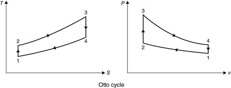
 FIGURE 5.1 The Otto Cycle


 (for four-stroke cycle engines)
 , where IMEP is indicated mean effective pressure.
 , where FMEP is friction mean effective pressure