Powered flight is a twentieth-century invention. The era of powered flight began on December 17, 1903 with the Wright brothers who designed, fabricated, and flew “The Flyer” in Kitty Hawk, North Carolina. The power onboard The Flyer was a gas powered, 12-hp reciprocating intermittent combustion engine. This type of engine, with a propeller, provided power to all (manned) aircraft until late 1930s. The history of aircraft gas turbine engine started in January 1930 with a patent issued to Frank Whittle in Great Britain. Figure 1.1 shows a p–v diagram and components of the Whittle engine as they appeared in the patent application. The flow pattern and engine assembly are shown in Figure 1.2. The performance of the W1 engine and the aircraft that flew it are shown in Figure 1.3. An engineer at work, Sir Frank Whittle, the inventor of jet engine, with a slide rule is shown in Figure 1.4. For more details on the Whittle turbojet see Meher-Homji (1997).
FIGURE 1.1Patent drawings of Sir Frank Whittle jet engine
FIGURE 1.2The assembly and flow pattern in Whittle jet engine
FIGURE 1.3Performance testing of Whittle jet engine, known as W1, and the experimental aircraft, Gloster E28/39 that flew it in1941. Source: Crown Publications
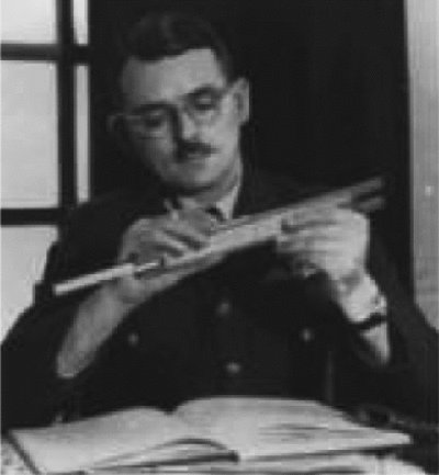
FIGURE 1.4Sir Frank Whittle with a slide rule. Source: Crown Publications
The gas turbine engine of Figure 1.1 is based on the Brayton cycle. The compression in the Whittle engine is achieved via a double-sided centrifugal compressor. The axial compressor had not been developed due to aerodynamic stability complications. The combustion takes place in a reverse-flow burner that is very large relative to other engine components. The straight through-flow burner had posed problems with stable combustion and thus a reverse-flow combustor provided the needed flame stability in the burner. The compressor shaft power is delivered from a single-stage axial flow turbine.
In an independent effort, Hans-Joachim Pabst von Ohain invented a turbojet engine in Germany that was granted a patent in 1936. In 1937, von Ohain’s engine designated as the He S-1 turbojet engine with hydrogen fuel was tested and produced a thrust of 250 pounds at 10, 000 rpm. Von Ohain’s engine was the first to be developed ahead of the Whittle engine and flew on the first jet-powered aircraft, Heinkel 178, in 1939. Both Whittle and von Ohain are credited as the coinventors of airbreathing gas turbine engine. Figure 1.5 shows the two inventors of the jet engine, a historical meeting on May 3, 1978.
FIGURE 1.5The first historic meeting between the two inventors of the jet engine took place in WPAFB on May 3, 1978. Source: AFRL/AFMC
The first production jet aircraft was Messerschmitt Me 262, shown in Figure 1.6. Two Jumo 004B turbojet engines powered the Messerschmitt Me 262 jet fighter. The Me 262 first-flight was on July 18, 1942. Dr. Anselm Franz of the Junkers Engine Company designed the Jumo 004, which was based on von Ohain’s patent. The Jumo 004B engine cutaway is shown in Figure 1.7. This engine has many modern gas turbine features such as axial-flow compressor and a straight throughflow combustor with air-cooling of the turbine and the nozzle. For more details see Meher-Homji (1996).
FIGURE 1.6The first production jet aircraft, Me 262
FIGURE 1.7Jumo 004B engine cutaway features an axial-flow compressor, a straight throughflow combustor, an air-cooled axial turbine, and an exhaust nozzle
The drawing of the Jumo 004B turbojet engine in Figure 1.7 shows an air-cooling system that bleeds air from the compressor and cools the turbine and the exhaust nozzle. The engine produces ∼2000 lb of thrust at an airflow of 46.6 lb/s. The engine pressure ratio is 3.14, turbine inlet temperature is 1427°F, and the specific fuel consumption is 1.4 lbm/h/lbf-thrust. The engine dry weight is ∼1650 lb, its diameter and length are ∼30 and 152 in., respectively. Engine component efficiencies are reported to be 78% compressor, 95% combustor, and 79.5% turbine. We will put these numbers in perspective when we compare them with their modern counterparts.
The jet engine came from Great Britain to the United States in 1941. The J-31 (also known by its company designation, I-16) was the first turbojet engine produced in quantity in the United States. It was developed from the General Electric I-A, which was a copy of the highly secret British “Whittle” engine. Figure 1.8 shows the J-31 gas turbine engine (courtesy of Air Force Museum).
FIGURE 1.8The first U.S. produced aircraft gas turbine engine. Source: Courtesy of US Air Force Museum
1.2 Innovations in Aircraft Gas Turbine Engines
In this section, we introduce the most significant innovations in gas turbine industry since the introduction of aircraft jet engine by Whittle and von Ohain. Dawson (1991) and Wallace (1996) as well as the NASA websites (references 5and 7) and publication (reference 8) should be consulted for further reading/information.
1.2.1 Multispool Configuration
In order to achieve a high-pressure compression system, two distinct and complementary approaches were invented in the United States. One is the multispool concept (developed by Pratt & Whitney) and the second is variable stator (developed by GE). The multispool concept groups a number of compressor stages together in two or three groups, known as the low-pressure compressor (LPC), intermediate-pressure compressor (IPC), and highpressure compressor (HPC). A different shaft that spins at different rotational speed drives each group. Figure 1.9 shows the Trent 1000, a modern Rolls-Royce engine that employs three spools. shows the Trent 1000, a modern Rolls-Royce engine that employs three spools.
FIGURE 1.9Three-spool gas turbine engine as developed by Rolls-Royce. Source: The Jet Engine, 2005. Reproduced by permission from The Jet Engine, Copyright Rolls-Royce plc 2005
1.2.2 Variable Stator
The need to adjust the flow direction in a multistage high-pressure ratio compressor (in starting and off-design) prompted Gerhard Neumann of GE to invent variable stator. By allowing the stators to rotate in pitch, compressors can operate at higher pressure ratios and away from stall. Modern gas turbine engines use variable stators in their LPC and IPC. The high-temperature environment of HPC has not been hospitable to variable stators.
1.2.3 Transonic Compressor
Better understanding of supersonic flow and the development of high strength-to-weight ratio titanium alloy allowed the development of supersonic tip fan blades. The transonic fan is born at a high shaft speed that creates a relative supersonic flow at the tip and a subsonic flow at the hub. A modern transonic fan stage produces a stage pressure ratio of ∼1.6. The Jumo 004B produced a cycle pressure ratio of 3.14 with eight stages, which means an average stage pressure ratio of ∼1.15. Therefore to achieve a pressure ratio of 3.14, we need only two transonic fan stages instead of eight. The higher compression per stage has allowed a reduction in engine weight, size, and part-count and has improved reliability. The advances in computational fluid dynamics (CFD) and nonintrusive testing techniques have paved the way for a better understanding of supersonic flow in compressors. A compressor flow simulation is shown in Figure 1.10(a). The rotor passage shock, boundary layer interaction, and flow separation are clearly visualized in Figure 1.10(a). An advanced transonic fan is shown in Figure 1.10(b) from Rolls-Royce.
FIGURE 1.10(a) CFD in transonic compressor rotor flowfield. Source: Courtesy of NASA; (b) advanced transonic fan. Source: Reproduced with permission from Rolls-Royce plc
1.2.4 Low-Emission Combustor
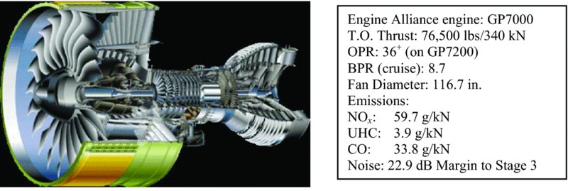
The gas turbine combustor has perhaps seen the most dramatic innovations/changes since the Whittle reverse-flow burner. A better understanding of the combustion process, from atomization and vaporization of the fuel to mixing with air and chemical reaction, has allowed efficient combustion to take place in small spaces. For example, compare the relative length and volume of the combustor in GP7000, shown in Figure 1.11, to the Whittle engine or Jumo 004B.
FIGURE 1.11Engine Alliance engine GP7000. Source: Reproduced with permission from the Engine Alliance. [Note: Engine Alliance is a 50/50 joint venture between GE Aviation and Pratt & Whitney]
In the textbox of Figure 1.11, we note that the combustor emissions are characterized by their nitric oxide formation, the so-called NOx, the unburned hydrocarbon (UHC) emission, and finally carbon monoxide formation in the exhaust nozzle flow. In order to achieve low levels of pollutant emissions, different concepts in “staged combustion” are developed by aircraft engine manufacturers (as shown in Figure 1.12).
FIGURE 1.12Concepts in low-emission combustor design. Source: Reproduced with permission from Rolls-Royce plc
1.2.5 Turbine Cooling
The need to cool the turbine stems from being able to operate the combustor at higher temperature (to produce more thrust) and to achieve turbine durability, that is, an improved component life. The first production turbojet engine, Jumo 004B, utilized internal cooling for the turbine blades. So, the concept is as old as the turbojet engine itself. Improved manufacturing techniques and better understanding of the flow physics involved in coolant ejection, mixing with hot gas, and three-dimensional flow in turbines have allowed for a rationed approach to coolant usage as well as component life enhancement. Figure 1.13 shows a single-and a multipass internal cooling of a turbine blade that incorporates film cooling as well as the thermal protection (or barrier) coating (TPC or TBC) to reduce the heat transfer to turbine blades.
FIGURE 1.13Turbine blade cooling. Source: Reproduced with permission from Rolls-Royce plc
1.2.6 Exhaust Nozzles
The concept of an exhaust nozzle for aircraft jet engine has changed from a simple convergent duct that was used to propel the hot exhaust gases to a variable-geometry and multitasked component in modern designs. The new tasks involve thrust reversing, thrust vectoring, noise suppression, and dynamic stability enhancement of maneuvering aircraft. To achieve these goals, advancements in nozzle cooling, actuation, and manufacturing had to be realized. Figure 1.14 shows a sophisticated propulsion layout (and nozzle system) in F-35 aircraft that has vertical takeoff/landing (VTOL) capability as well as roll control in hover. Figure 1.15 shows a ±20° vector thrust in F119 engine developed by Pratt & Whitney for F-22 “supercruise” aircraft.
FIGURE 1.14Propulsion layout for vertical landing and stability of F-35 Joint Strike Fighter. Source: Reproduced with permission from Rolls-Royce plc
FIGURE 1.15F119 engine that powers F-22 Raptor is shown in vector thrust. Source: Reproduced with permission of United Technologies Corporation, Pratt & Whitney
1.2.7 Modern Materials and Manufacturing Techniques
Nonmetallics and composite materials represent a sizable change in modern material usage in aircraft and jet engines. Metal matrix composites technology offers a high strength-to-weight ratio relative to titanium and nickel superalloys suitable for fan blades. Single crystal turbine blades offer more resistance to vibration and thus fatigue failure. A manufacturing technique that utilizes a honeycomb core with a composite skin offers weight and stress reductions in fan blades. Compressor weight savings are derived from bladed disk “Blisk” and bladed ring “Bling” manufacturing technology. All these are shown in Figure 1.16.
FIGURE 1.16Advanced materials and manufacturing techniques. Source: Reproduced with permission from Rolls-Royce plc
An example of a modern engine is EJ200, which powers the “Eurofighter” Typhoon (shown in Figure 1.17). Its design features are tabulated in Table 1.1.
FIGURE 1.17Cutaway of EJ200, an afterburning turbofan engine designed for the Eurofighter. Source: Reproduced with permission from Rolls-Royce plc
The modern materials and the manufacturing techniques that we have discussed are described in Table 1.1. Compare the turbine inlet temperature (T14) in EJ200 and Jumo 004B, or thrust-to-weight ratio.
1.3 New Engine Concepts
In this section, we examine a few modern concepts in aircraft propulsion. The first one deals with advanced turboprop (ATP) and geared turbofan (GTF) engines. The ATP pushes the frontier of turboprops from low speed flight into high subsonic cruise Mach numbers (M0∼0.8) and GTF allows turbofan engines to use a gearbox and achieve high-efficiency ultra-high bypass ratio capability, the so-called UHB (for ultra-high bypass). Next, we present an exciting airbreathing rocket, the Single-Stage to Orbit (SSTO) engine that is under promising development in the United Kingdom. The next two concepts harness unsteadiness as a means of thrust production. The fourth is a triumph of microelectro-mechanical (MEM) device manufacturing. The rest are combined cycles.
1.3.1 Advanced Turboprop (ATP) and Geared Turbofan (GTF)
Conventional propellers lose their thrust production capability when their tip operates in supersonic flow and stalls. In the United States, Pratt & Whitney/Allison Gas Turbine, GE Aviation and NASA collaborated in developing the technology of advanced turboprop engines in the 1970s and 1980s. These engines are generally called Propfan, while GE’s gearless, direct-drive ATP is called the Unducted Fan (UDF). The advanced propellers operate with relative supersonic tip Mach number (MT∼-1.1.1.15) without stalling! With increasing capability in relative tip Mach number of the propeller, the cruise flight Mach number is increased to M0∼-0.8.0.82. Several configurations in co-and counterrotating propeller sets and pusher versus tractor configurations were developed and tested. The advanced propellers are highly swept at the tip (between 30.40.) to improve tip efficiency at high relative Mach numbers. Figure 1.18 shows an ATP. Courtesy of GE Aviation and NASA.
FIGURE 1.18GE Unducted Fan (UDF) or GE-36. Source: Reproduced with permission from General Electric Company
The technology of the ultra-high bypasss (UHB) turbofan engine developed at Pratt & Whitney utilizes an advanced gear system that improves low-pressure spool operating efficiency. The fan pressure ratio in UHB engines is reduced to accommodate bypass ratios of 12+, which improves propulsive efficiency, cuts down on fuel consumption, and reduces jet noise and engine emissions. The first single-aisle transport aircraft equipped with GTF entered service in 2013. The engine architecture is readily scalable to include widebody aircraft thrust levels as well. Figure 1.19 shows the cutaway of the P&W GTF engine, that is, the PW1000G geared turbofan engine family. The advanced fan gear system on the low-pressure spool is visible in Figure 1.19 (trimetric view).
FIGURE 1.19Cutaway view of the PW1000G UHB geared turbofan engine. Source: Reproduced by permission of United Technologies Corporation, Pratt & Whitney
1.3.2 Advanced Airbreathing Rocket Technology
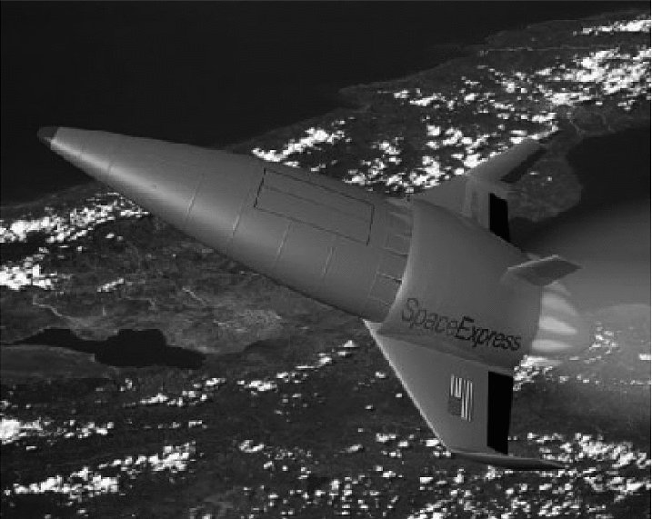
An ultra-light weight precooler heat exchanger uses a closed-cycle Helium loop to cool the air from 1000 to −150°C in a fraction of a second (actually in 10 ms). This innovative counterflow precooler/heat exchanger technology is at the heart of an innovative airbreathing rocket engine that is capable of horizontal takeoff, climb, acceleration to Mach 5+ using subcooled air in its rocket engines and then transition to pure rocket mode above 20+ km altitude. The air intake system uses a translating cone which completely closes the inlet in the pure rocket mode. Due to its versatility, this combined cycle engine is dubbed SABRE—Synergetic Air Breathing Rocket Engine—and is being developed by Reaction Engines Ltd. in the United Kingdom (Figure 1.20). At the time of this writing, the critical components of SABRE are undergoing testing and with promising results.
The reusable SSTO winged aerospace plane that is designed around SABRE technology is in its early development phase; it is called SKYLON. The configuration of this vehicle is shown in Figure 1.21. Extensive technical information on SABRE and SKYLON can be found on the Reaction Engines website.
FIGURE 1.20Cutaway of SABRE shows the counterflow heat exchanger integrated in the air intake system. Source: Reproduced by permission of Reaction Engines
FIGURE 1.21SKYLON in Low-Earth Orbit, with open payload bay. Source: Reproduced by permission of Reaction Engines
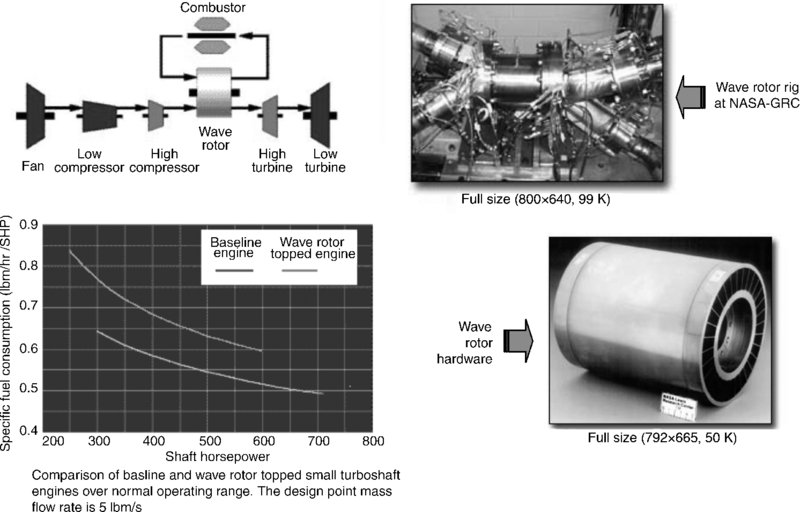
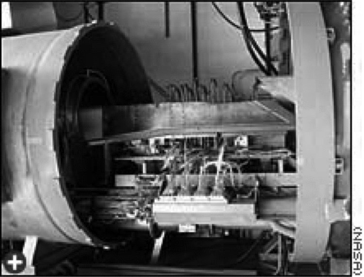
1.3.3 Wave Rotor Topping Cycle
Wave rotor creates a pressure gain in the combustor, instead of the baseline pressure drop, thereby enhances cycle efficiency. As a simple example of a higher efficiency cycle that takes advantage of constant-volume combustion, we may examine the Humphrey cycle. Schematics of the wave rotor topping cycle concept, a wave rotor hardware, and a test rig at NASA-Glenn Research Center are shown in Figure 1.22. A performance chart of the wave rotor topping cycle for small turboshaft engines, also in Figure 1.22, shows nearly 10% fuel savings compared with a baseline engine.
FIGURE 1.22Schematics of the wave rotor toping cycle wave rotor hardware and a test rig at NASA. Source: Courtesy of NASA
1.3.3.1 Humphrey Cycle versus Brayton Cycle
An ideal Humphrey cycle is shown in Figure 1.23 in a pressure–volume and temperature–entropy diagrams. Combustion takes place at constant volume in a Humphrey cycle, whereas it takes place at constant pressure in an ideal Brayton cycle. We utilize the definition of cycle efficiency and thermodynamic principles to get Brayton and Humphrey cycle efficiencies.
FIGURE 1.23Constant-volume and constant-pressure combustion cycles
Cycle efficiency of a constant-pressure combustion (Brayton) cycle: 1–2–5–6–1, is:
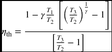
The cycle efficiency of a constant-volume combustion (Humphrey cycle: 1–2– 3–4–1) is:
where γ is the ratio of specific heats.
Cycle efficiency in Humphrey cycle depends on T1/T2 and on the temperature ratio T3 / T2 (in effect p3/p2). Figure 1.24 shows the ideal cycle thermal efficiency of a Brayton and a Humphrey cycle for T1 = 288 K, T2 = 800 K, and T3 that varies between 1600 and 2500 K, for γ = 1.4.
FIGURE 1.24Ideal thermal efficiency of Humphrey and Brayton cycles for γ =1.4, and T1 = 288 K, T2 = 800 K, and T3 that varies between 1600 and 2500 K
Note: In this example, cycle (thermal) efficiency improvements between ∼7% and ∼14% are observed.
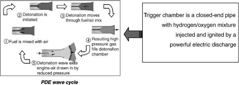
1.3.4 Pulse Detonation Engine (PDE)
The Pulse Detonation Engine (PDE) is a constant-volume combustion ramjet that is capable of producing static thrust. The operation of a PDE is similar to a pulsejet except combustion in a pulsejet is based on the principle of deflagration that is a slow wave front with low-pressure ratio. The PDE creates a detonation wave, which is akin to an explosion that creates high-pressure shock waves. To get a feel for how often these explosions occur, we note the frequency of these explosions that is ∼60 detonations per second. The PDE wave cycle is shown in Figure 1.25.
FIGURE 1.25The Pulse Detonation engine with a trigger chamber. Source: Courtesy of NASA
1.3.5 Millimeter-Scale Gas Turbine Engines: Triumph of MEMS and Digital Fabrication
Microchip manufacturing techniques and some vivid imaginations have given birth to millimeter-scale gas turbine engines. Figure 1.26 shows a “button” size gas turbine engine that is designed, manufactured, and tested at MIT. At these scales, the rotor has to spin at ∼1, 000, 000 rpm to achieve the needed compression for the cycle. The process of fuel injection, atomization, vaporization, and combustion is a challenge among the myriad of other mechanical challenges in the manufacturing of millimeter-scale gas turbine engine.
FIGURE 1.26Millimeter-scale gas turbine engine with the rotor and external shell. Source: Courtesy of MIT Gas Turbine Laboratory
1.3.6 Combined Cycle Propulsion: Engines from Takeoff to Space
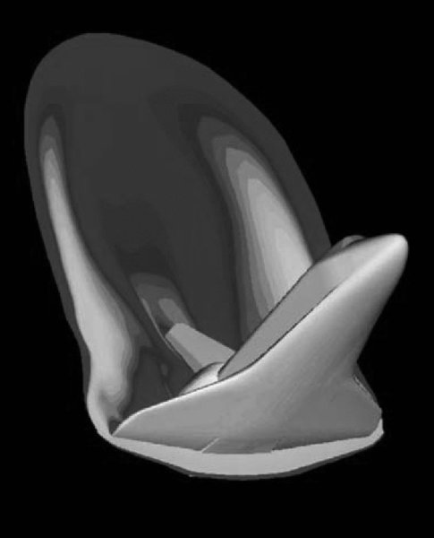
We have examined the SABRE technology in SSTO in a previous section (1.3.2). In this section, we examine other concepts in single-stage to orbit propulsion systems. There are several developments that address combined cycles as a means of producing efficient propulsion over a wide range of flight speeds, typically from takeoff to hypersonic Mach numbers. An example of this approach is found in the airbreathing rocket engine, which is a Rocket-Based Combined Cycle (RBCC) engine. At takeoff where conventional ramjets are incapable of producing thrust, a rocket is fired (with an ejector nozzle configuration to get a thrust boost) that accelerates the vehicle to, say, Mach 2. At Mach 2, the rocket is turned off and air intakes are opened to start a subsonic ramjet engine operation. The airbreathing engine switches from the subsonic to supersonic combustion ramjet (scramjet) near Mach 5. The scramjet will accelerate the vehicle to, say, Mach 15. The air intakes close at Mach 15 and rocket operation resumes accelerating the vehicle to orbital speeds (∼Mach 25 or higher). The rocket with the ejector nozzle and computational results of Mach contours are shown in Figure 1.27. An RBCC engine is capable of reducing launch costs by two orders of magnitude. An artist’s concept of the vehicle is shown in Figure 1.28. An RBCC flight weight engine system test was conducted in 2006. Figure 1.29 shows the test firing of the airbreathing rocket.
FIGURE 1.27An RBCC air-augmented rocket with an ejector nozzle (with Mach contours computed). Source: Courtesy of NASA
FIGURE 1.28Artist’s drawing of an advanced launch vehicle using RBCC propulsion. Source: Courtesy of NASA
FIGURE 1.29Testing of an airbreathing rocket at NASA. Source: Courtesy of NASA
1.4 New Vehicles
There are exciting new vehicles on the drawing board for many different missions at many different speeds. The interest in uninhabited aerial vehicles (UAVs) has prompted new configurations such as the Northrop–Grumman X-47 “Pegasus, ” or the tailless agility aircraft X-36 from Boeing, or the X-45A Unmanned Combat Air Vehicle (UCAV), or the X-48 using Blended Wing-Body technology. NASA’s interest in hypersonic flight and scramjet propulsion has prompted the X-43 series of technology demonstrator vehicles. Some of these aircraft are shown in Figure 1.30.
FIGURE 1.30Uninhabited aerial vehicles and NASA X43 technology demonstrators. Source: Boeing and NASA. Reproduced with permission.
1.5 Summary
There are exciting developments in aerospace propulsion and vehicle design:
Physics-based computer simulation/design
Advanced composite materials
Digital fabrication and manufacturing will take unprecedented precision from nano-scale up, including 3-D printing and digital assembly
Exciting new vehicles on the horizon
Hybrid and electric propulsion for light aircraft, e.g., UAVs
High-efficiency, low-emission, quiet engines for transport aircraft, e.g., PW1000G, geared ultra-high bypass turbofan engine
Rocket-based combined cycle propulsion: from takeoff to orbit!
New lunch vehicles and missions for hypersonic aircraft and space exploration
“There’s a lot of room at the bottom” Richard Feynman said. Enter MEMS-GT engines!
Manned-mission to Mars
US-Europe-China-Russia active in commercial space race!
An additional example of computational flow simulation is shown in Figure 1.31.
FIGURE 1.31Flowfield simulations around the Space Shuttle in reentry using computational fluid dynamics. Source: Courtesy of NASA
1.6 Roadmap for the Second Edition
We begin our studies in propulsion with a review of compressible flow that involves friction and heat transfer in Chapter 2. Engine thrust and performance parameters are discussed in Chapter 3 where rigorous derivation of uninstalled thrust and installation effects are presented. Gas turbine engine cycle analysis both for ideal and real components are studied in Chapter 4, including a new section on propeller theory and a section on Ultra-High Bypass (UHB) engines. The Uninhabited Aerial Vehicle (UAV) propulsion system is new to the second edition and is presented in Chapter 5. Aircraft engine inlets and nozzles, over a wide speed range, are analyzed in Chapter 6. A new section on jet noise and the Chevron Nozzle is added to Chapter 6. The principles of combustion are detailed in Chapter 7. The specific characteristics of the primary and afterburners, as in flameholding, are discussed in the same chapter. A discussion of alternative jet fuels from renewable sources is also included in Chapter 7. The turbomachinery principles and their application to axial-flow compressor, centrifugal compressor and the axial-flow turbine are extensively derived and discussed in Chapters 8 through 10. Additional design guidelines are added to turbomachinery chapters. Chapter 11 aims to integrate all the gas turbine engine components into a unified system, from component matching to engine off-design analysis. The new material in this chapter includes the principles of engine performance testing. Chapter 12 is dedicated to chemical rocket and hypersonic propulsion where rockets, ramjets, scramjet and combined cycles are discussed. An overview of available computational and online resources and links, related to propulsion, is also assembled in a separate appendix. Two new appendices are added to the book, namely Appendix K, where 45 ten-minute quizzes are listed for use by the instructors and the students, and Appendix L, where aircraft propulsion “Rules of Thumb” and trends are listed for information and quick reference.
References
Dawson, V.P., Engines and Innovation: Lewis Laboratory and American Propulsion Technology, NASA SP-4306, 1991.
Meher-Homji, C.B., “The Development of Junkers Jumo 004B—The World’s First Production Turbojet, ” ASME Paper No. 96-GT-457, 1996.
Meher-Homji, C.B., “The Development of Whittle Turbojet, ” ASME Paper No. 97-GT-528, 1997.
Meher-Homji, C.B., “Pioneering Turbojet Developments of Dr. Hans von Ohain—From HeS 01 to HeS 011, ” ASME Paper No. 99-GT-228, 1999.
Wallace, L.E., Flights of Discovery: Fifty Years at the NASA Dryden Flight Research Center, National Aeronautics and Space Administration, Washington, DC, 1996.
1.1 The Carnot cycle sets the limit on thermal efficiency of a heat engine operating between two temperature limits. Show that ideal Carnot efficiency is
What is the thermal efficiency if T1 = 288 K and T2 = 2000 K?
1.2 The ideal Brayton cycle operates between two pressure limits as shown. It is the model of an airbreathing jet engine, such as a turbojet or ramjet engine. Show that ideal Brayton cycle efficiency is
What is the thermal efficiency of the Brayton that has T1 = 288 K and T2 = 864 K? Note that maximum cycle temperature T3 has no effect on cycle thermal efficiency.
1.3 The Humphrey cycle operates a constant-volume combus-tor instead of a constant-pressure cycle like the Brayton cycle. Show that
is the thermal efficiency of an ideal Humphrey cycle (as shown).
Let us use the same T1 as in Problems 1.1 and 1.2, that is, T1 = 288 K. Let us use the same temperature T2 as in Problem 1.2, that is, T2 = 864 K.
Finally, let us use the same maximum cycle temperature as in Carnot (Problem 1.1), that is, Tmax = 2000 K. With the ratio of specific heats γ = 1.4, calculate the thermal efficiency of the Humphrey cycle. Compare the answer with Brayton cycle efficiency.
1.4 The rotor of a millimeter-scale gas turbine engine has a radius of 1 mm. It has to reach a tip, or rim speed of nearly the speed of sound for an effective compression. Assuming that the speed of sound is 340 m/s, calculate the rotor rotational speed in revolutions per minute (rpm).
1.5 Specific fuel consumption (sfc) projects the fuel economy of an engine, that is, it measures the fuel flow rate (say in pound-mass per hour or g/s) that leads to a production of a unit thrust (say 1 pound-force or 1 Newton). Two sets of numbers are copied from Table 1.1 (from EJ200 specification), which are
Sfc (max. power)
0.81 lbm/h/lbf
Sfc w. AB
1.75 lbm/h/lbf
Thrust (SL)
13, 500 lbf
Thrust w. AB
20, 250–22, 250 lbf
First note that afterburner (AB) use more than doubles the fuel consumption while boosting the thrust by only ∼50%. This explains the sparse use of an afterburner in aircraft mission. Now to quantify, calculate the amount of additional fuel burned in 30 min of afterburner use (producing 21, 000 lbf thrust) as compared with 30 min of no afterburner use (producing 13, 500 lbf thrust).

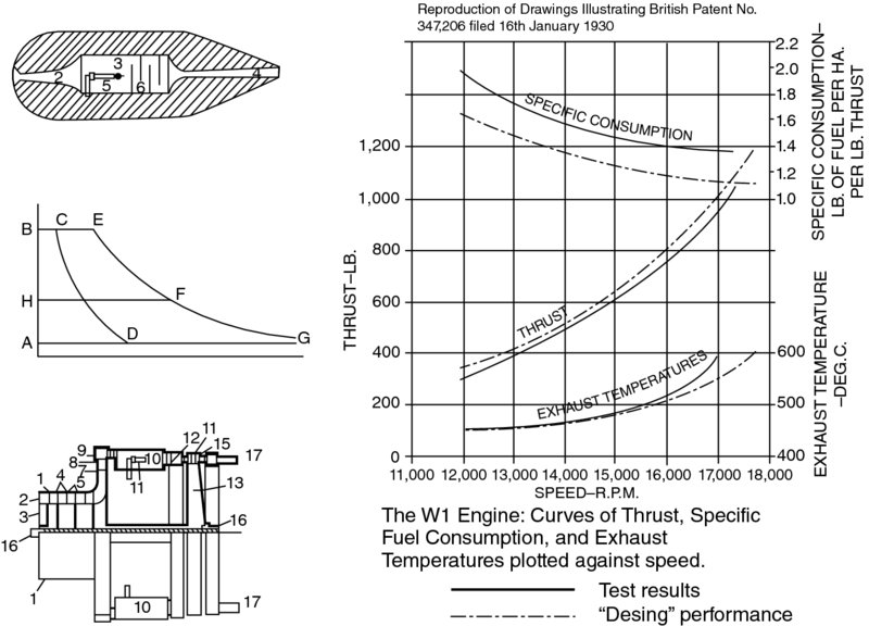
 FIGURE 1.1 Patent drawings of Sir Frank Whittle jet engine