Lesson 23. Taking Apart a MacBook
Reference Files
MacBook (13-inch) service manual (macbook_13in.pdf)
Time
This lesson takes approximately 1 hour to complete.
Goals
Remove a faulty logic board from a MacBook
In the previous lesson, you learned how simple it is to upgrade the MacBook (13-inch), by installing memory and a hard drive. This lesson focuses on a more complete disassembly of the unit leading to the replacement of a faulty logic board.
This lesson is meant to accompany the Apple Service Source manual, provided as a resource on this book’s companion website, www.peachpit.com/ats.deskport3, which demonstrates the procedures in full detail including reassembly. If you are an Apple Authorized Service Provider (AASP), practice the Take Apart and reassembly at your own speed until you feel confident that you can replace any MacBook component to factory specifications. AASPs should download and refer to the latest service manual before servicing any Apple product. Non-AASPs should read the service manual and this text to become familiar with the procedures.
Note
If anyone other than an AASP opens a MacBook for any reason, and any damage to the unit results, the repair of such damage will not be covered under the Apple warranty or the AppleCare Protection Plan.
Required Tools and Equipment
In addition to the standard electrostatic discharge (ESD) wrist strap and mat—which you should always use, following the guidelines discussed in Lesson 4, “Safe Working Procedures and General Maintenance”—you will need the following tools and equipment:
• Magnetic Phillips #0 and #00 screwdrivers
• Nylon probe tool (also called a black stick) or other nonconductive nylon or plastic flat-blade tool
• Stack of books, weighted boxes, or other means of support for display while removing and replacing left clutch block
• Alcohol wipes
• Thermal grease syringe
• Felt-tip pen
• Coin
• Clean, soft, lint-free cloth
• Access card
Taking Apart a MacBook
At each stage of the Take Apart procedure, we proceed from component to component, from the outside in. The lead technician has assigned to you the task of replacing a faulty logic board in this unit, after performing the required troubleshooting. Proceed to page 112 of the service manual to review the preliminary steps that you must perform prior to removing the logic board. After reviewing these preliminary procedures, go to page 13 in the service manual to familiarize yourself with the battery removal procedure. Always complete steps in the order they are provided.
Battery
A lithium-ion (Li-ion) battery provides power for the MacBook when it is not being powered by its power adapter. Whenever you are opening a MacBook or any portable computer, the first step is to remove all power from the unit, including the power adapter and the battery.
Warning
Always shut down the computer before opening it to avoid damaging the internal components or causing injury. After you shut down the computer, the internal components can be very hot. Let the computer cool down for 30 minutes before continuing.
- Complete steps 1 through 6 on page 14 of the service manual to prepare to remove the battery.
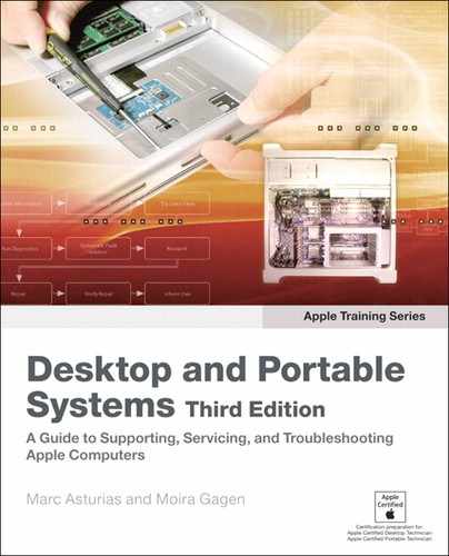
- Complete step 7 to release the battery latch. Use only a coin to unlock the battery to prevent scratching the unit.
- Perform step 8 and lift the battery from the battery bay. Set aside the battery on a soft cloth.
Battery removal
RAM Door (L-Bracket)
Proceed to page 16 in the service manual to become familiar with the random-access memory (RAM) door removal procedure.
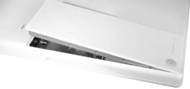
- Perform steps 1 and 2 on page 17 to begin the procedure. The three captive screws will loosen but will not come out.
Captive screws (circled in blue)
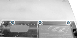
- Perform step 3 on page 18 to remove the L-shaped RAM door. Be careful not to bend it. Set aside the RAM door for later reassembly.
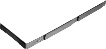
RAM door
Memory
Turn to page 21 of the service manual and review the memory module removal procedure. The memory upgrade you performed in the previous lesson will have made this procedure more familiar to you.
- Complete steps 1 through 3 on page 21. Pay particular attention to any special cautions or notes. Avoid damaging the dual inline memory module (DIMM) levers by moving them only in a sideways direction, as shown below.
- Perform step 4 on page 22 to slide out the memory cards from the battery bay.
Top Case (with Keyboard)
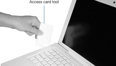
Proceed to page 28 in the service manual to become familiar with the top case removal procedures. You will need an access card for this procedure.
You will remove many screws during this procedure, and it is important to keep track of where they came from. It is possible to place a longer screw in the incorrect hole. One suggestion for noting screw locations is to use a large paper packing slip and draw the shape of the computer on the adhesive layer. When you remove the screws, you can place them in the drawing where they belong. Another technique is to use a plastic ice cube tray, and store the screws by component, in the order they were removed. In either case, the goal is to place the correct screw in the hole to which it corresponds.
Note
To prevent scratching the computer housing, use a soft cloth as a protective layer.
- Perform the first two steps in the procedure on page 29 of the service manual, carefully noting the location and length (5.5 mm and 3 mm) of the screws removed.
- Perform step 3 on page 29 to remove the screws at the back of the computer, again taking note of the different locations and lengths (8 mm and 12 mm).
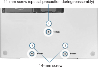
- Perform step 4 on page 30 to remove the screws on the bottom case. Take note of the center 11-mm screw: if replaced with a longer screw, it may damage the logic board. Later you will need to install these screws in a particular order, as noted in the service manual.
- Perform steps 5 and 6 on page 31 to remove the 3-mm front-edge screws. Remove the screws in the order shown.
Tip
You may remember this clever Apple mnemonic when performing this procedure: “2, 4, 7, 9...loosens the top case every time.”
- Perform step 7 on page 31 to remove the 6-mm screws on both outer sides of the battery bay. Do not remove the inner screws near the battery connector.
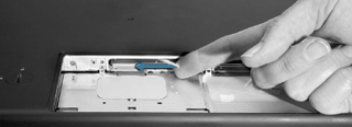
- Perform step 8 on page 32 to remove the three screws near the battery bay, near the RAM slots. Due to the recessed location of the screws, you must keep the screwdriver in line with the screw heads as much as possible. Upon reassembly, incorrect installation of these screws could result in the computer wobbling while in use.
- Review and perform steps 9 and 10 on page 32.
Note
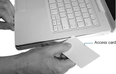
Inserting a tool too far or performing this step too quickly could result in breaking some of the snaps that secure the top case. Be especially careful with the left front corner of the top case. Starting at the left corner and working in a counter-clockwise direction, use an access card tool to open the gap along the front of the top case, around the perimeter, and to the right side above the optical drive slot.
- Perform step 11 on page 33 to release the remaining top case snaps.
- Perform steps 12 and 13 on pages 34 and 35 to disconnect the trackpad cable. Note that both MacBook models are depicted in the service manual.
- Perform step 14 on page 36 to lift away the top case from the computer, and place it on a soft cloth to protect its surface.
Having removed the top case, the computer is very vulnerable to damage, either from ESD or by leaving a screw dropped inside during reassembly. Take proper precautions during the next steps. Proceed to the next preliminary step.
AirPort Extreme Card
Proceed to page 45 of the service manual and become familiar with the procedure necessary to remove the AirPort Extreme Card.
- Perform steps 1 and 2 on page 46 to remove the screws that hold the AirPort Extreme Card in place.
- Perform step 3 on page 46 to remove the AirPort Card.
Remove the AirPort Card in the direction shown by the arrows.
- Perform steps 4 and 5 on page 47 to move aside the speaker cables and disconnect the two antenna cables attached to the AirPort Extreme Card. Place the AirPort Card in an ESD-safe static bag to prevent damage to its sensitive components.
MagSafe DC-In Board
Proceed to page 50 to remove this component.
- Perform steps 1 and 2 on page 51 to remove the cables and screws from the connector.
- Perform step 3 on page 52, carefully tilting the MagSafe DC-In Board upwards from the port with a nylon probe tool.
During removal, tilt the connector in the direction indicated by the arrow.
Left Speaker
Proceed to page 54 of the service manual to review the left speaker removal procedure. You completed step 2 of this procedure when you removed the 8.5-mm ground screw during removal of the AirPort Extreme Card. You will not need to perform step 7, as the DC-In was removed during the MagSafe DC-In removal procedure.
Tip
Note the routing of the speaker cable so that you can place it in the same position during reassembly.
- Perform steps 1 and 3 on page 55 of the service manual.
- Perform step 4 on page 56 to remove the 6-mm speaker screw.
- Perform steps 5 and 6 on page 56 to pivot the speaker upward for removal.
- Place the left speaker in a separate location from the removed screws and other components to avoid contact with the speaker’s magnets.
I/O Frame (with Upper EMI Shield)
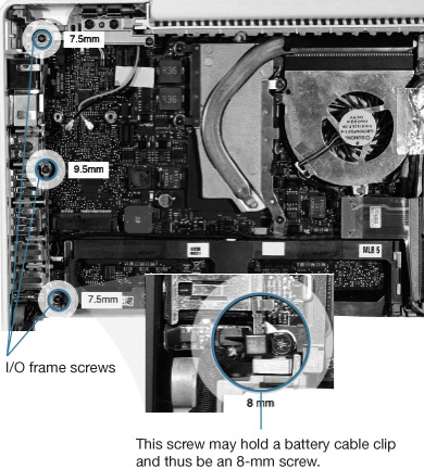
- Familiarize yourself with the I/O frame disassembly procedure on page 108 of the service manual, noting the locations and sizes of the screws you will be removing during the procedure.
- Complete the first step on page 109 of the service manual to remove the screws from the I/O frame.
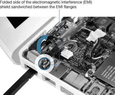
- Perform steps 2 and 3 on pages 110 to remove the EMI shield and I/O frame. Set aside these components for later replacement.
Fan
Review the fan removal procedures on page 70 of the service manual. Pay particular attention to screw placement and size, as well as tape location.
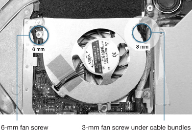
- Perform steps 1 and 2 on page 71 to remove the fan screws. The 3-mm screw is normally hidden underneath the cable bundles.
- Perform steps 3 and 4 on page 72 to tilt up and disconnect the fan cable and remove the fan.
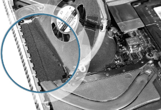
The adhesive foam, circled here, that overlaps the fan and heatsink must be replaced before reassembling the computer, as it tears easily.
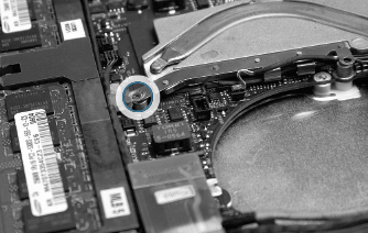
Heatsink
Proceed to page 73 in the service manual to become familiar with the heatsink removal procedure, taking care to note screw placement, thermal grease precautions, and heatsink differences.
- Perform the first step on page 74 of the service manual to remove the four 8-mm screws. Notice the flexible ground tab sandwiched between the lower-right screw and heatsink.
Lower-right screw anchoring the ground tab (circled in blue)
- Perform steps 2 and 3 on page 75 to loosen the heatsink and disconnect the thermistor connectors from the logic board. Note the routing of the thermistor cables and the placement of the thermal sponge to aid reassembly of the unit.
Note
Proper heat dissipation is crucial to the operation of any computer, but even more so in portable computers that have miniaturized components, including a smaller case and fan. To prevent serious damage to the unit, take the utmost care in following the precautions regarding thermal foam and thermal grease prior to reassembly.
- Proceed to page 77 in the service manual to review “Checking the Thermal Grease,” which will be required during reassembly.
- Proceed to page 83 to review “Comparing Heatsinks,” taking note of the two types of heatsinks. You will use this information during reassembly.
Logic Board
Having performed all ten preliminary steps, you can review the logic board removal procedures on page 112 of the service manual.
- Perform the first step on page 113 to disconnect the optical drive flex cable from the logic board.
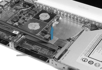
Remove the optical flex drive cable in the direction of the arrow.
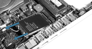
- Perform steps 2 and 3 on page 114 to disconnect the low-voltage differential signaling (LVDS) cable, Bluetooth antenna cable, and hard drive cable connector from the logic board.
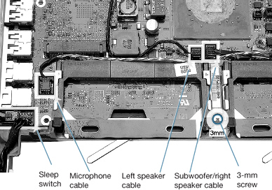
- Perform step 4 on page 115 to remove the 3-mm screw next to the lower end of the midframe.
- Perform step 5 on page 115 to remove the 3-mm screw between the memory card carriers, as well as four cables. Use a black stick to raise and disconnect the sleep switch.
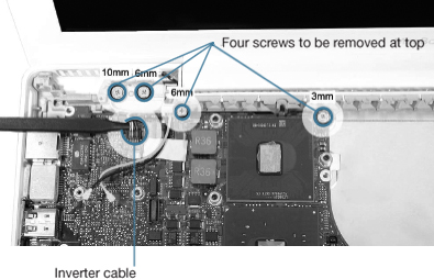
- Perform step 6 and 7 on page 116 of the manual to support the display, disconnect the inverter cable and four screws, and remove the left clutch block and cap.
- Perform step 8 on page 117 to remove the faulty logic board. If the logic board is not easily removed with a small rocking motion, use a black stick or other nonconductive tool between the side of the bottom housing and ports to gently assist the logic board removal.
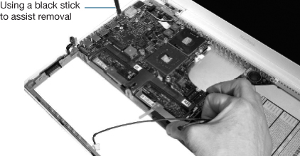
Notice the angle of the logic board as it is being removed.
- Place the faulty logic board in the ESD-safe static bag that was shipped with the replacement logic board for return to Apple.
When You Are Finished
The Take Apart procedures in this lesson have shown you the step you’ll need to take before replacing the logic board. This replacement procedure will require careful attention to detail, since the component can be easily damaged if not replaced correctly.
- Replace the logic board and preliminary steps components, carefully following the instructions and all precautions in the service manual, beginning on page 118.
- Verify that the system is working correctly by starting it up, running Apple Hardware Test (AHT), and performing a few user tasks, such as copying files and launching Apple-supplied applications.
Lesson Summary
• Whenever you work on the internal components of any computer, it is imperative that you follow proper ESD procedures and follow steps in the service manual in the order provided.
• Each product has a different Take Apart procedure, which is explained in detail in its particular service manual. The information presented in this lesson applies to the MacBook (13-inch).
• Gaining access to a particular component often requires the removal of several other components first. Each component must be properly protected from damage as it is removed.
• You must unplug the power adapter and remove the battery to prevent the MacBook from turning on during the Take Apart procedure.
• Some parts, such as thermal foam, must be replaced—not reused—when you reassemble the computer.
• Take precautions with fragile internal components to protect them from ESD damage and surface damage. Watch for screws and other small objects that can fall into the computer, shorting the components upon startup.