
Chapter 20. Digital Audio Production
20.1. Digital Audio Workstations (DAWs)
When applied to a digital audio application, a computer hardware platform is termed a digital audio workstation (DAW). The two ubiquitous standards in the audio arena are the Apple Macintosh computer family (or “Macs”), which use Motorola processors, and the IBM PC and compatibles (PCs), which use Intel-based processors. The Macintosh was always “audio ready” because it was designed with an audio capacity beyond the PC’s dumb “beep.” Other small personal computers (especially Atari ST) became very popular in music applications. The Atari ST computer (Figure 20.1) was another 68000 based computer (like the Apple Mac). Including a powerful ROM- based operating system and a desktop metaphor very like that now commonplace in Windows, the Atari was pretty much ahead of its time in the early 1980s. However, the Atari ST owes its tremendous success, and continuing long-overdue existence in many recording studios, to the decision of the designers to include MIDI IN and OUT sockets on the side of the machine. This made the Atari the only ready-to-go, “plug and play” MIDI sequencer platform, a fact reflected in the number of software products designed for it.
Figure 20.1. Atari ST computer.

PowerPCs and PowerMacs are machines built around a reduced instruction set computing (RISC) processor developed jointly by IBM, Apple, and Motorola. They are designed to run operating system software that supports both PC and Mac applications and are designed to be especially good at handling large data files typical of media components. RISC technology is especially noted in workstation computers. Three computers designed and manufactured by the American high-end computer company Silicon Graphics Inc. (SGI) make extensive use of RISC technology. SGI’s subsidiary, MIPS Technologies, Inc., designs the RISC processor technology inside SGI machines. MIPS’ new R5000 MIPS RISC processor delivers a peak of 480 million floating point operations per second (MFLOPS)—up to twice as fast as Intel’s 200-MHz Pentium Pro and over seven times as fast as a 133-MHz Pentium! Workstations from SGI are also finding their way into high-end audio production.
SGI is the leading manufacturer of high-performance visual computing systems. The company delivers interactive three-dimensional graphics, digital media, and multiprocessing super-computing technologies to technical, scientific, and creative professionals. SGI manufactures some of the best tools for multimedia creation, as well as white-heat video, audio, and graphics stand-alone packages. They also provide specialist tools for HTML, hypermedia page creation, and serving for the creation of multimedia creations on the Internet/World Wide Web (WWW). SGI has its headquarters in Mountain View, California. SGI’s products include the Indy, which is a “value” RISC workstation utilizing a 64-bit system architecture and MIPS processors. On the audio side it has digital audio I/O as well as analogue ports. The Indigo 2 is aimed as a cost-effective desktop alternative to older style dedicated video production hardware. The Onyx is a super-computer with a graphics bias! SGI also manufactures the CHALLENGE Media Server for the broadcast television environment. Table 20.1 is the audio subsystem specification for Onyx and CHALLENGE and represents the typical digital audio performance from desktop audio. The option also provides for microphone input and headphone output but these figures are not quoted here.
Table 20.1. Audio subsystem specification for onyx and challenge
| Number of channels | 4 analogue (16 bit), 2 digital (24 bit) |
| Input analogue route | |
| Input Z | 20 k ohms |
| Input amplitude | From 0.63 V pp to 8.4 V pp for full-scale modulation (this level is adjustable under software control) |
| Frequency response | ±0.81 dB 20 Hz to 20 kHz |
| THD+noise | Less than 0.007% 20 Hz to 20 kHz |
| Residual noise | –86 dB unweighted |
| Cross talk | –82 dB at 1 kHz, –67 dB at 20 kHz |
| ADC type | 16-bit Delta-Sigma |
| Output analogue route | |
| Output Z | 600 ohms |
| Output level | 4.7 V pp (4.4 dBV) for 0 dBFS |
| Sampling rates | 32, 44.1, 48 kHz, or divisors selectable |
| Frequency response | ±1.2 dB 20 Hz to 20 kHz |
| THD+noise | Less than 0.02% 20 Hz to 20 kHz |
| Residual noise | –81 dB unweighted |
| Cross talk | –80 dB at 1 kHz, –71 dB at 20 kHz |
| Digital serial I/O | |
| Type | Coaxial only |
| Input Z | 75 ohms, transformer coupled |
| Input level | 0.5 V pp into 75 ohms |
| Sample rates | 30 kHz to 50 kHz |
| Output Z | 75 ohms, transformer coupled |
| Output level | 0.5 V when terminated in 75 ohms |
| Coding | AES-3, IEC 958 |
Note that the input ports for audio (both analogue and digital) conform to consumer levels and practice even though SGI themselves refer to the digital inputs as AES/EBU.
20.1.1. Hard-Disk Editing
Not long ago, most recordings were mastered on two-track analogue tape. Whether the performance was by a soloist, small classical or rock ensemble, or full orchestra, the good “takes” of a recording session were separated from the bad and joined together using razor-blade editing. Using this technique, the tape was physically cut with a razor blade and joined using a special sticky tape. With the high tape speeds employed in professional recording, accurate editing was possible using this technique and many fine recordings were assembled this way. Any engineer who has been involved with razor-blade editing will know that it is a satisfying skill to acquire but it is tricky and it is always fraught with difficulties. The reason being that a mistimed or misjudged edit is difficult to put right once the first “incision” has been made! So much so that a dub or copy of the original master tapes was sometimes made for editing lest the original master should be irreparably damaged by a poor edit. Unfortunately, because analogue recording is never perfect, this meant that editing inevitably meant one tape-generation of quality loss before the master tape had left the studio for production. The advent of digital audio has brought about a new vista of possibility in sound editing. Apart from the obvious advantages of digital storage, that once the audio signal is in robust digital form it can be copied an infinite number of times, thus providing an identical tape “clone” for editing purposes, the arrival of the ability to process digital audio on desktop PCs has revolutionized the way we think about audio editing, providing a flexibility undreamed of in the days of analogue mastering machines.
Editing digital audio on a desktop microcomputer has two major advantages.
- An edit may be made with sample accuracy, by which is meant, a cut may be made with a precision of 1/40,000th of a second!
- An edit may be made nondestructively, meaning that when the computer is instructed to join two separate takes together, it doesn’t create a new file with a join at the specified point, but instead records two pointers that instruct on subsequent playback to vector or jump to another data location and play from the new file at that point.
In other words, it “lists” the edits in a new file of stored vector instructions. Indeed this file is known as an edit decision list. (Remember that the hard-disk doesn’t have to jump instantaneously to another location because the computer holds a few seconds of audio data in a RAM cache memory.) This opens the possibility of almost limitless editing in order to assemble a “perfect” performance. Edits may be rehearsed and auditioned many times without ever “molesting” the original sound files.
20.1.2. Low-Cost Audio Editing
Most audio capture cards like the Creative Labs Soundblaster come bundled with a primitive sound-file editing software. Usually this permits a “butt-join” edit (the exact analogy of a razor blade splice) between different sound files or between data loaded onto the clipboard in rather the same way as a word processor works on text files. In fact, Creative Labs’ Wave Studio utility is quite powerful and affords some manipulations (such as the ability to operate on left and right channels of a stereo signal separately) that exceed the capabilities of some low-end professional editing software. However, the big disadvantage with Wave Studio is that it does not allow for nondestructive editing. An inexpensive and truly excellent package is authored by Minnetonka Software Inc. and is known as FastEddie. This “value” package permits nondestructive editing to sample accuracy, preaudition of edit points, the ability to mix files, time “stretch” or compress the WAV file, and normalize gain so that a WAV file may be increased in gain just enough so that the largest excursion on the file is brought almost to within clipping level, thus maximizing dynamic range. The utility can also be used to generate audio effects such as echo and reverb and reversal of the sound file so that it plays backward. In order to facilitate the judgment of edit points, most editing software provides an on-screen waveform display. This may be zoomed at will: IN to examine individual samples and OUT to reveal musical sections or the whole file.
An example is shown in Figure 20.2, which is an off-screen capture of a FastEddie window. The highlighted sections in the lower, read-only part of the window are ready for editing in the top editing part of the window. Given its price, FastEddie has a number of very professional features, among these is the ability to cross-fade at edit points rather than to produce a butt join (Figure 20.3). The advantage of this feature is due to the complex nature of musical sounds. Even if an edit is made at a precise point in a musical score, a discontinuity is produced in the audio waveform. This discontinuity usually manifests itself as an audible click or “bump.” The use of cross-fading ameliorates these effects. FastEddie also provides facilities for producing fade-outs and fade-ins on complete sound-file data.
Figure 20.2. FastEddie digital audio editor.

Figure 20.3. Audio editing with cross-fades for edit points.

20.1.3. Professional Audio Editing
For professional music editing, most sophisticated editing systems still exist, ranging from the reasonable to the very expensive. At the higher end, the platforms are predominantly Mac based. The crème-de-la-crème in this field being the Sonic Solutions—the choice of music editing system for most classical music producers. The high-end systems mostly show up with their own proprietary hardware and it is here, as much as in software, that these systems score over desktop PC systems using a 16-bit sound card. The professional units typically offer better quality A to D and D to A conversion and more transparent signal processing.
20.1.4. Multitrack Hard-Disk Recording
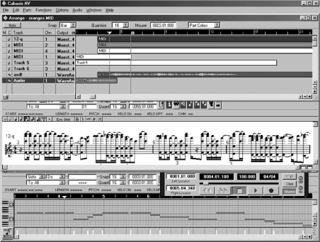
Hard-disk capacity and computer speeds are not so high that multitrack recording on a DAW is commonplace. A typical home-studio application (Cubase AV) is illustrated in Figure 20.4, which shows the combination of multitrack audio and MIDI data, all within one screen environment.
Figure 20.4. Multitrack audio recording combined with MIDI sequencing.
20.1.5. Plug-ins
As more and more audio production is gradually taking place on computer platforms, or on the desktop, hardware manufacturers are now producing software programs that imitate their outboard hardware in a digital signal processor (DSP) program. This software interfaces with mixing and editing programs (via mutually agreed data-exchange standards) so as to provide the metaphor of “outboard” facilities on the desktop. These programs are known as plug-ins.
20.2. Audio Data Files
Digital representations of sound, when stored on computer, are stored just like any other kind of data, as files. A number of different file formats exist in common usage. Most sound files begin with a header consisting of information describing the format of that file. Characteristics such as word length, number of channels, and sampling frequency are specified so that audio applications can read the file properly. One very common type of file format is the WAV (or Wave) format. This is a good example because it demonstrates all the typical features of a typical audio file.
20.2.1. Wav Files
WAV files are a version of the generic RIFF file format. This was codeveloped by Microsoft and IBM. RIFF represents information in predefined blocks, preceded by a header that identifies exactly what the data are. This format is very similar to the audio interchange file format (AIFF) format developed by Apple (see later) in that it supports monaural and multichannel samples and a variety of sample rates. Like AIFF, WAVE files are big and require approximately 10 Mbytes per minute of 16-bit stereo samples with a sampling rate of 44.1 kHz.Here is a hexadecimal representation of the first 128 bytes of a WAV file.
26B7:0100 52 49 46 46 28 3E 00 00–57 41 56 45 66 6D 74 20 RIFF(>..WAVEfmt
26B7:0110 10 00 00 00 01 00 01 00–22 56 00 00 22 56 00 00 .....”V.. “V..
26B7:0120 01 00 08 00 64 61 74 61–04 3E 00 00 80 80 80 80 ...data.>..........
26B7:0130 80 80 80 80 80 80 80 80–80 80 80 80 80 80 80 80 ............
26B7:0140 80 80 80 80 80 80 80 80–80 80 80 80 80 80 80 80 ............
26B7:0150 80 80 80 80 80 80 80 80–80 80 80 80 80 80 80 80 ............
26B7:0160 80 80 80 80 80 80 80 80–80 80 80 80 80 80 80 80 ............
26B7:0170 80 80 80 80 80 80 80 80–80 80 80 80 80 80 80 80 ............
The header provides Windows with all the information it needs. First off, it defines the type of RIFF file, in this case, WAVEfmt. Notice the bytes, which are shown underlined. The first two, 22 and 56, relate to the audio sampling frequency. Their order needs reversing to read; 5622 hexadecimal, which is equivalent to 22 050 in decimal—in other words, 22-kHz sampling. The next two inform the Media Player that the sound file is 1 byte per sample (mono) and 8 bits per sample.
20.2.2. AU Files
AU (or μ-law—pronounced mu-law) files utilize an international standard for compressing audio data. It has a compression ratio of 2:1. The compression technique is optimized for speech (in the United States it is a standard compression technique for telephone systems; in Europe, a-law is used). This file format is found most frequently on the Internet where it is used for ‘.au’ file formats, alternately know as ‘Sun audio’ or ‘NeXT’ format. Even though it’s not the highest quality audio file format available, its nonlinear, logarithmic coding scheme results in a relatively small file size, which is ideal for applications where download time is a problem.
20.2.3. AIFF and AIFC
The Audio Interchange File Format (AIFF) allows for the storage of monaural and multichannel sample sounds at a variety of sample rates. AIFF format is frequently found in high-end audio recording applications. Originally developed by Apple, this format is used predominantly by SGI and Macintosh applications. Like WAV, AIFF files can be quite large; 1 min of 16-bit stereo audio sampled at 44.1 kHz usually takes up about 10 megabytes. To allow for compressed audio data, Apple introduced the new AIFF-C, or AIFC, format, which allows for the storage of compressed and uncompressed audio data. AIFC supports compression ratios as high as 6:1. Most of the applications that support AIFF playback also support AIFC.
20.2.4. MPEG
The International Standard Organisation’s Moving Picture Expert Group (MPEG) is responsible for one of the most popular compression standards in use on the Internet today. Designed for both audio and video file compression, MPEG-I audio compression specifies three layers, and each layer specifies its own format. The more complex layers take longer to encode but produce higher compression ratios while keeping much of an audio file’s original fidelity. Layer 1 takes the least amount of time to compress, but layer 3 yields higher compression ratios for comparable quality files.
20.2.5. VOC
Creative Voice (.voc) is the proprietary sound file format that is recorded with Creative Lab’s Sound Blaster and Sound Blaster Pro audio cards. This format supports only 8-bit mono audio files up to sampling rates of 44.1 kHz and stereo files up to 22 kHz.
20.2.6. Raw PCM Data
Raw Pulse Code Modulated (PCM) data are sometimes identified with the .pcm, but it sometimes has no extension at all. Since no header information is provided in the file, you must specify the waveform’s sample rate, resolution, and number of channels to the application to which it is loaded.
20.3. Sound Cards
Available in a bewildering array of different guises, for serious audio work, 16-bit cards only are suitable, and even then beware of very poor noise levels. Computers differ widely in their suitability as devices for high-quality audio. The Creative Technology Ltd. Sound Blaster card family has some of the most widespread sound cards used in the PC world. Supplied standard with a four operator FM sound generator chip for sound synthesis, Creative Labs offer a wavetable-based upgrade. Sound Blaster ships with sound file editing software. The card comes with a utility program for controlling the analogue mixer on the card where the various sound sources are combined and routed. This utility is called Creative Mixer and it’s illustrated in Figure 20.5. Note that fader style controls are implemented in software so as to provide a familiar user interface. Control over CD, MIDI synthesizer, and WAV file replay, as well as line and microphone inputs, are provided. Global (all sources) equalization is also provided.
Figure 20.5. Creative Labs’ Creative Mixer utility.

20.4. PCI Bus Versus ISA Bus
Most PCs, until the arrival of the Pentium, were provided with a PC/AT bus (or ISA bus) for connecting peripherals (such as sound cards, frame grabbers, and so on). The ISA bus operates with 16-bit data bus and a 16-bit address bus and operates with a divided clock. The ISA bus limits real-world transfer rates to around 1–2 Mbytes/s, which is just enough for high-quality, dual-channel audio. The Peripheral Component Interconnect (PCI) bus is incorporated in newer Pentium-based IBM PCs. PCI is a local bus, so named because it is a bus which is much “closer” to the CPU. Local buses run at a much higher rate and PCI offers considerable performance advantages over the traditional ISA bus, allowing data to be transferred at between 5 and 70 Mbytes/s; allowing the possibility of real-time, multitrack audio applications. The PCI bus is a processor-independent bus specification that allows peripheral boards to access system memory directly (under the aegis of a local bus controller) without directly using the CPU, employing a 32-bit data bus and a 64-bit address bus at full clock speed. Installation and configuration of PCI bus plug-in cards are much simpler than the equivalent installation on the ISA bus. Commonly referred to as the “plug-and-play” feature of the PCI bus, this user transparency is achieved by having the PCs BIOS configure the plug-in card’s base address and interrupt level at power-up. Because all cards are automatically configured, conflicts between them are eliminated. It is a process that can only be done manually with cards on the ISA bus. The PCI Bus is not limited to PCs; it is the primary peripheral bus in the PowerPC and PowerMacs from Apple. Incorporation of the PCI bus is planned for other RISC-based processor platforms.
20.5. Disks and Other Peripheral Hardware
Read/write compact disk (CD-R) drives are now available at a price within the reach of the small recording studio, and recordable media are less than $2. CD-R drives are usually SCSI based so PCs usually have to have an extra expansion card fitted to provide this interface (see later). Recordable CDs rely on a laser-based magneto-optical system to “burn” data into the recorded medium. Once written, data cannot be erased. Software exists (and usually comes bundled with the drive) which enables the drive to be used as a data medium or an audio carrier (or sometimes as both). There exist a number of different variations of the standard ISO-9600 CD-ROM. The two most important are the (HFS/ISO) Hybrid disk, which provides support for CD-ROM on Mac and PC using separate partitions, and the Mixed mode disk, which allows one track of either HFS (Mac) or ISO-9600 information and subsequent tracks of audio.
A number of alternative removable media are available and suitable for audio use; some are based on magnetic storage (like a floppy disk or a Winchester hard-drive) and some on magneto-optical techniques—nearer to CD technology: Bernoulli cartridges are based on floppy disk, magnetic storage technology. Disks up to 150 MByte are available. Access times are fast; around 20 ms. SyQuest are similar. Modern SyQuest cartridges and drives are now available in up to 1.3 GByte capacity and 11-ms access times, making SyQuest the nearest thing to a portable hard drive. Magneto-optical drives use similar technology to CD, they are written and read using a laser (Sony is a major manufacturer of optical drives). Sizes up to 1.3 GBytes are available with access times between 20 and 30 ms.
20.6. Hard Drive Interface Standards
There are several interface standards for passing data between a hard disk and a computer. The most common are the SCSI or Small Computer System Interface, the standard interface for Apple Macs; the IDE or Integrated Drive Interface, which is not as fast as SCSI; and the Enhanced IDE interface, which is a new version of the IDE interface that supports data transfer rates comparable to SCSI.
20.6.1. IDE Drives
The Integrated Drive Electronics interface was designed for mass storage devices, in which the controller is integrated into the disk or CD-ROM drive. It is thereby a lower cost alternative to SCSI interfaces in which the interface handling is separate from the drive electronics. The original IDE interface supports data transfer rates of about 3.3 Mbytes per second and has a limit of 538 Mbytes per device. However, a recent version of IDE, called enhanced IDE (EIDE) or Fast IDE, supports data transfer rates of about 12 Mbytes per second and storage devices of up to 8.4 Gbytes. These numbers are comparable to what SCSI offers. However, because the interface handling is handled by the disk drive, IDE is a very simple interface and does not exist as an interequipment standard, that is, you cannot connect an external drive using IDE. Due to demands for easily upgradable storage capacity, and for connection with external devices such as recordable CD players, SCSI has become the preferred bus standard in audio applications.
20.6.2. SCSI
An abbreviation of Small Computer System Interface and pronounced “scuzzy,” SCSI is a parallel interface standard used by Apple Macintosh computers (and some PCs) for attaching peripheral devices to computers. All Apple Macintosh computers starting with the Macintosh Plus come with a SCSI port for attaching devices such as disk drives and printers. SCSI interfaces provide for fast data transmission rates,; up to 40 Mbytes per second. In addition, SCSI is a multidrop interface, which means that you can attach many devices to a single SCSI port.
Although SCSI is an ANSI standard, unfortunately, due to ever higher demands on throughput, SCSI comes in a variety of “flavors!” Each is used in various studio and mastering applications and, as a musician engineer, you will need to be aware of the differences. The following varieties of SCSI are currently implemented:
- SCSI-1: Uses an 8-bit bus and supports data rates of 4 Mbytes/s.
- SCSI-2: Same as SCSI-1, but uses a 50-pin connector instead of a 25-pin connector. This is what most people mean when they refer to plain SCSI.
- Fast SCSI: Uses an 8-bit bus and supports data rates of 10 Mbytes/s.
- Ultra SCSI: Uses an 8-bit bus and supports data rates of 20 Mbytes/s.
- Fast Wide SCSI: Uses a 16-bit bus and supports data rates of 20 Mbytes/s.
- Ultra Wide SCSI: Uses a 16-bit bus and supports data rates of 40 Mbytes/s; this is also called SCSI-3.
20.6.3. Fiber Channel
Fiber channel is a data transfer architecture developed by a consortium of computer and mass storage device manufacturers. The most prominent Fibre Channel standard is Fibre Channel Arbitrated Loop (FC-AL), which was designed for new mass storage devices and other peripheral devices that require very high bandwidth. Using an optical fiber to connect devices, FC-AL supports full-duplex data transfer rates of 100 Mbit/s. This is far too high a transfer rate to be relevant as an audio-only standard. However, in multichannel applications and in multimedia applications (with video, for example) Fibre Channel may well find its way into the modern studio, so much so that FC-AL is expected to eventually replace SCSI for high-performance storage systems.
20.6.4. Firewire (IEEE 1394) Interface
The “Firewire” (IEEE 1394 interface) is an international standard, low-cost digital interface intended to integrate entertainment, communication, and computing electronics into consumer multimedia. Originated by Apple Computer as a desktop LAN, Firewire has been developed by the IEEE 1394 working group. Firewire supports 63 devices on a single bus (SCSI supports 7, SCSI Wide supports 15) and allows buses to be bridged (joined together) to give a theoretical maximum of thousands of devices. It uses a thin, easy to handle cable that can stretch further between devices than SCSI, which only supports a maximum “chain” length of 7 meters (20 feet). Firewire supports 64-bit addressing with automatic address selection and has been designed from the ground up as a “plug and play” interface. Firewire can handle 10 Mbytes per second of continuous data with improvements in the design promising continuous throughput of 20–40 Mbytes per second in the very near future and a long-term potential of over 100 Mbytes/s. Much like LANs and WANs, IEEE 1394 is defined by the high-level application interfaces that use it, not a single physical implementation. Therefore, as new silicon technologies allow high higher speeds and longer distances, IEEE 1394 will scale to enable new applications.
20.7. Digital Noise Generation—Chain Code Generators
The binary sequence generated by a chain code generator appears to have no logical pattern; it is, to all intents and purposes, a random sequence of binary numbers. The code is generated by a shift register that is clocked at a predetermined frequency and whose input is derived from a network that develops a function of the outputs from the register.
A basic form of chain code generator is illustrated in Figure 20.6, which consists of a 4-bit shift register whose input is derived from the output of an exclusive-OR gate, itself fed from the penultimate and last output of the shift register. The output from the chain code generator may be taken in serial form (from any of the data-latch outputs) or in parallel form (from all the data latch outputs). In operation, imagine that the output of stage B starts with a 1 as power is applied, but that all the other outputs start with a 0. Note that the output of the XOR gate will only equal 1 when its inputs are of a different state (i.e., nonidentical). We can now predict the ensuing pattern that results as the shift register is clocked:
| State | Output (A,B,C,D) |
|---|---|
| 0 (initial) | 0,1,0,0 |
| 1 | 0,0,1,0 |
| 2 | 1,0,0,1 |
| 3 | 1,1,0,0 |
| 4 | 0,1,1,0 |
| 5 | 1,0,1,1 |
| 6 | 0,1,0,1 |
| 7 | 1,01,0 |
| 8 | 1,1,0,1 |
| 9 | 1,1,1,0 |
| 10 | 1,1,1,1 |
| 11 | 0,1,1,1 |
| 12 | 0,0,1,1 |
| 13 | 0,0,0,1 |
| 14 | 1,0,0,0 |
| 15 | 0,1,0,0 |
| 16 | 0,0,1,0 |
| 17 | 1,0,0,1 |
| 18 | 1,1,0,0 |
| etc. |
Figure 20.6. Chain-code generator.

Note that, at state 15, the pattern starts to repeat. This sequence is known as the maximum-length sequence. The fact that the outputs states are predictable illustrates that the output of the code generator is not really random at all but is a pseudo-random binary sequence (PRBS). The sequence does, however, have some very “random” qualities—like a very nearly equal number of 1 s and 0 s (think of it a coin-tossing machine)! Practically, this lack of true randomness does not matter provided that the sequence is long enough to appear random in any particular application. In every case of an n-stage, chain code generator, the longest (maximal length) sequence of 1 s and 0 s repeats after (2 e n – 1) states. Note that, as illustrated in Figure 20.6, a pathological condition can occur if all outputs power up in an identical 0 state—in which case 0 s will propagate indefinitely around the chain code generator, resulting in no output. Practical circuits have to include provision to prevent this situation from ever occurring. Indeed it is precisely because of the necessity to avoid this “forbidden” all zeros state that the output of the chain code generator illustrated in Figure 20.6 consists of a cycle of 15 (rather than the more intuitively expected 16) states.
It can be shown mathematically that the output binary sequence from the chain code generator has a frequency spectrum extending from the repeat frequency of the entire sequence up to the clock frequency and beyond. The noise is effectively flat (within 0.1 dB) to about 0.12 of the clock frequency (Fc). The noise source is –3 dB at 0.44 Fc and falls off rapidly after that. For most applications (audio included), simple low-pass filtering of the digital maximal-length sequence results in white Gaussian noise, provided that the breakpoint of the low-pass filter is well below the clock frequency of the register (say 0.05 Fc to 0.1 Fc), that is, in the region where the spectrum of the digital noise is constant. The analogue filter may be a simple 6-dB/octave RC circuit, but usually a sharper active filter is desirable.
Uncited Reference
[1]