
Chapter 23. Loudspeakers
The conversion from electronic signals to sound is the formidable task of the loudspeaker. In this chapter, Ian Sinclair examines principles and practice of modern loudspeaker design.
A loudspeaker is a device that is actuated by electrical signal energy and radiates acoustic energy into a room or open air. The selection and installation of a speaker, as well as its design, should be guided by the problem of coupling an electrical signal source as efficiently as possible to an acoustical load. This involves the determination of the acoustical load or radiation impedances and selection of a diaphragm, motor, and means for coupling the loaded loudspeaker to an electrical signal source. The performance of the speaker is intimately connected with the nature of its acoustic load and should not be considered apart from it.
23.1. Radiation of Sound
Sound travels through the air with a constant velocity depending on the density of the air; this is determined by its temperature and the static air pressure. At a normal room temperature of 22°C and static pressure po of 751 mm Hg (105N/m2), the density of the ambient air is 1.18 Kg/m3. Under these conditions, the velocity of sound is 344.8 m/s, but 340 m/s is a practical value. The wavelength of a sound (X) is equal to the velocity of propagation described by its frequency:(23.1)
![]() The sensation of sound is caused by compressions and rarefactions of the air in the form of a longitudinal oscillatory motion.
The energy transmitted per unit area varies as the square of the distance from the source. The rate with which this energy
is transmitted expresses the intensity of the sound, which directly relates to the sensation of loudness. This incremental variation of the air pressure is known as sound pressure, which, for practical purposes, is what is measured in determining the loudness of sound.
The sensation of sound is caused by compressions and rarefactions of the air in the form of a longitudinal oscillatory motion.
The energy transmitted per unit area varies as the square of the distance from the source. The rate with which this energy
is transmitted expresses the intensity of the sound, which directly relates to the sensation of loudness. This incremental variation of the air pressure is known as sound pressure, which, for practical purposes, is what is measured in determining the loudness of sound.
Sound pressure level (SPL) is defined as 20 times the logarithm to base 10 of the ratio of the effective sound pressure (P) to the reference sound pressure (Pref ):(23.2)
![]() Pref approximates to the threshold of hearing and numerically is 0.0002 microbar (2×10⁻⁵ N/m2).
Pref approximates to the threshold of hearing and numerically is 0.0002 microbar (2×10⁻⁵ N/m2).
The intensity (I) of a sound wave in the direction of propagation is (23.3)
 The intensity level (IL) of a sound in decibels is(23.4)
 The relationship between IL and SPL is found by substituting Equation (23.2) for intensity (I) in Equation (23.4). Inserting values for Pref and 7ref gives (23.5)
![]() It is apparent that the intensity level IL will equal the sound pressure level SPL only if poC=400 Rayls. For particular combinations of temperature and static pressure this will be true, but under “standard measuring
conditions” of (23.6)
It is apparent that the intensity level IL will equal the sound pressure level SPL only if poC=400 Rayls. For particular combinations of temperature and static pressure this will be true, but under “standard measuring
conditions” of (23.6)
![]() The error of –0.1 dB can be neglected for practical purposes.
The error of –0.1 dB can be neglected for practical purposes.
23.2. Characteristic Impedance
The characteristic impedance is the ratio of the effective sound pressure to the particle velocity at that point in a free, plane, progressive sound wave. It is equal to the product of the density of the medium times the speed of sound in the medium (p0C). It is analogous to the characteristic impedance of an infinitely long, dissipation-less, transmission line. The unit is the Rayl, or Newton s/m3.
23.3. Radiation Impedance
When a vibrating diaphragm is placed in contact with air, its impedance to motion is altered; the added impedance seen by the surfaces that emit useful sound energy is termed “radiation impedance.” The radiation reactance is usually positive, corresponding to an apparent mass. Both reflective mass and resistance as seen by the diaphragm depend on its size, shape, frequency, and the acoustical environment in which it radiates.
23.4. Radiation from a Piston
Many radiating sources can be represented by the simple concept of a vibrating piston located in an infinitely large rigid wall. The piston is assumed to be rigid so that all parts of its surface vibrate in phase and its velocity amplitude is independent of the mechanical or acoustic loading on its radiating surface.
Figure 23.1 shows the problem: we wish to know the sound pressure at a point A located distance r and angle θ from the center of the piston. To do this, we divide the surface of the piston into a number of small elements, each of which is a simple source vibrating in phase with all the other elements. The pressure A is, then, the sum in magnitude and phase of the pressures from these elementary elements. For r large compared with the radius of the piston a, the equation will be(23.7)
![]() where u0=RMS velocity of the piston and J1() is Bessel function of the first order. Note that the portion of Equation (23.7) in square brackets yields the directivity pattern.
where u0=RMS velocity of the piston and J1() is Bessel function of the first order. Note that the portion of Equation (23.7) in square brackets yields the directivity pattern.
Figure 23.1. Piston in infinitely plane wall.

23.5. Directivity
At frequencies where the wavelength of sound (X) is large compared with the diameter of the piston, the radiation is spherical. As the frequency is increased, the wavelength becomes comparable or less than the piston diameter and the radiation becomes concentrated into a progressively narrowed angle.
The ratio of pressure P0 at a point set at an angle θ off the axis, to the on axis pressure PA at the same radial distance, is given by (23.8)
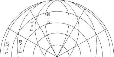
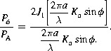 Figure 23.2 shows radiation patterns for different ratios of λ/D. The radiation from a piston is directly related to its velocity, and we can compute the acoustic power radiated and the sound
pressure produced at any given distance in the far field.
Figure 23.2 shows radiation patterns for different ratios of λ/D. The radiation from a piston is directly related to its velocity, and we can compute the acoustic power radiated and the sound
pressure produced at any given distance in the far field.
Figure 23.2. Directivity of piston as a function of piston diameter and wavelength.
23.6. Sound Pressure Produced at Distance r
Low frequencies. When the piston diameter is less than one-third wavelength (ATa<1.0) it is essentially nondirectional and can be approximated by a hemisphere whose RMS volume velocity ux equals:(23.9)
![]() and the RMS sound pressure at distance r is:(23.10)
and the RMS sound pressure at distance r is:(23.10)
![]() and total power radiated Wt is:(23.11)
and total power radiated Wt is:(23.11)
![]() Medium frequencies. At frequencies where the radiation from the piston becomes directional but still vibrates as one unit, the pressure produced
at a distance r depends on the power radiated and the directivity factor Q:(23.12)
Medium frequencies. At frequencies where the radiation from the piston becomes directional but still vibrates as one unit, the pressure produced
at a distance r depends on the power radiated and the directivity factor Q:(23.12)
![]() The mechanical impedance in MKS mechanical ohms (Newton-seconds/meter) of the air load upon one side of a plane piston mounted
in an infinite baffle and vibrating sinusoidally is(23.14)
The mechanical impedance in MKS mechanical ohms (Newton-seconds/meter) of the air load upon one side of a plane piston mounted
in an infinite baffle and vibrating sinusoidally is(23.14)
![]() where Zm is mechanical impedance in Newton seconds/meter, α is radius of piston in meters, ρ0 is density of gas in kg/cubic meter, c is velocity of sound in meters/second, RmR is mechanical resistance in Newton seconds/meter (this component varies with frequency), X is mechanical reactance in Newton seconds/meter, K is ∞/c=2π/λ=wave number, and J1K1 is two types of Bessel function given by the series:(23.15)
where Zm is mechanical impedance in Newton seconds/meter, α is radius of piston in meters, ρ0 is density of gas in kg/cubic meter, c is velocity of sound in meters/second, RmR is mechanical resistance in Newton seconds/meter (this component varies with frequency), X is mechanical reactance in Newton seconds/meter, K is ∞/c=2π/λ=wave number, and J1K1 is two types of Bessel function given by the series:(23.15)
![]() (23.16)
(23.16)
![]() where W is 2Ka.
where W is 2Ka.
Figure 23.3 shows graphs of the real and imaginary parts of this equation:
![]() It will be seen that for values of Ka<, the reactance X varies as the first power of frequency, while the resistive component varies as the second power of frequency. At high frequencies
(i.e., Ka>5) the reactance becomes small compared with resistance, which approaches a constant value. The graph can be closely approximated
by the analogue (Figure 23.4), where
It will be seen that for values of Ka<, the reactance X varies as the first power of frequency, while the resistive component varies as the second power of frequency. At high frequencies
(i.e., Ka>5) the reactance becomes small compared with resistance, which approaches a constant value. The graph can be closely approximated
by the analogue (Figure 23.4), where

![]() It will be seen that the reactive component behaves as a mass loading on the diaphragm and is a function of diaphragm area
only.
It will be seen that the reactive component behaves as a mass loading on the diaphragm and is a function of diaphragm area
only.
Figure 23.3. Air load on a plane piston; mechanical impedance ref.; driving point.

Figure 23.4. Impedance analogue of Figure 23.3.

The term Ka has special significance: it relates the diaphragm radius to the wavelength of sound at any particular frequency. It is numerically equal to (23.17)
![]() where a is radius of the diaphragm and λ is wavelength.
where a is radius of the diaphragm and λ is wavelength.
When the wavelength λ is greater than the circumference of the diaphragm, the loudspeaker behaves substantially as a point source and the sound field pattern is essentially omnidirectional. At the same time the radiation resistance increases with frequency. Thus at frequencies below Ka=1, the increase in radiation resistance with frequency is exactly balanced by the reduction in velocity of the diaphragm with frequency due to its mass reactance (assuming there are no resonances in the diaphragm) and the sound pressure will be constant. At values above Ka=1, the radiation resistance (neglecting the minor “wiggles”) becomes constant, but because of focusing due to the diaphragm dimensions being greater than λ, the sound pressure on the axis remains more or less constant. The velocity of sound in air is approximately 340 m/s, therefore a 150-mm (6 inch)-diameter diaphragm will behave as a point source to a limiting frequency of about 720 Hz; thereafter it begins to focus. Various artifices (such as corrugations) are used with paper cones to extend this range, with more or less success. This was the classic premise that Rice and Kelogg postulated in 1925 when they reinvented the moving coil loudspeaker, and it is still fundamental today.
To summarize, the loudspeaker should operate under mass-controlled conditions and (neglecting directional effects due to focusing of the diaphragm) sound pressure will be constant and independent of frequency; for a given magnet and coil system it will be inversely proportional to the total mass of the diaphragm and moving coil system.
23.7. Electrical Analogue
The analysis of mechanical and acoustical circuits is made very much easier by the application of analogues in which mass is equivalent to inductance, compliance to capacitance, and friction to resistance. Using SI units, direct conversion among acoustical, mechanical, and electrical elements can be performed.
The three basic elements (RCL) of acoustical, electrical, and mechanical, systems are shown schematically in Figure 23.5. The inertance M of an acoustic system is represented by the mass of gas contained in a constriction that is short enough so that all particles are assumed to move in phase when actuated by a sound pressure. The compliance C of the system is represented by an enclosed volume, with its associated stiffness. It should be noted that the mechanical analogue of acoustic compliance is not mechanical stiffness, but rather its reciprocal, mechanical compliance Cm=Vs. Although resistance of an acoustic system may be due to a combination of a number of different factors, irrespective of its origin, it is conveniently represented by narrow slits in a pipe, for the viscous forces that arise when gas is forced to flow through these slits always results in the dissipation of energy.
Figure 23.5. Acoustical, electrical, and mechanical analogues.

The Helmholtz resonator may be graphically represented by Figure 23.6, but converting it to its electrical analogue shows it to be a simple resonant circuit, which can be analyzed easily using general circuit theorems.
Figure 23.6. Schematic representations of a Helmholz resonator.

The beauty of the analogue method of analysis is that it is possible, by using various transformation equations, to refer the acoustic and electrical parameters to the mechanical side or, conversely, the mechanical and acoustic parameters to the electrical side, etc. For the purpose of this analysis the electrical and acoustical parameters are referred to the mechanical side. The diaphragm can be thought of as an acoustic/mechanical transducer, that is, a device for transforming acoustic energy to mechanical energy, and vice versa. Under these circumstances it will also act as an impedance transformer, that is, it will convert acoustic inertance into mechanical mass and acoustic compliance into mechanical compliance and acoustic resistance into mechanical resistance. The equivalent mechanical values of the acoustical quantities may be obtained from the following relationships:(23.18)
 (23.19)
![]() (23.20)
(23.20)
 (23.21)
![]() (23.22)
(23.22)
![]() (23.23)
(23.23)

23.8. Diaphragm/Suspension Assembly
Assuming that the diaphragm behaves as a rigid piston and is mass controlled, the power response is shown in Figure 23.7 where f0 is the system fundamental resonant frequency. Above this, the system is mass controlled and provides a level response up to ft; this corresponds to Ka=2 (see Figure 23.3). Above this frequency the radiation resistance is independent of frequency, and the response would fall at 12 dB/octave, but because of the “directivity” effect, the sound field is concentrated into a progressively narrower beam. The maximum theoretical rate of rise due to this effect is 12 dB/octave, thus the on-axis HF response should be flat. In real life this is only approximated.
Figure 23.7. Power response of an infinitely rigid piston.

23.9. Diaphragm Size
It has been found experimentally that the effective area of the cone is its projected or base area. This should not be confused with the advertised diameter of the loudspeaker, which is anything from 25 to 50 mm greater than the effective cone diameter. In direct radiator loudspeakers and at low frequencies, radiation resistance is proportional to the fourth power of the radius (square of the area) and the mass reactance to the cube of the radius. The resistance/reactance ratio (or power factor) of the radiation impedance is therefore proportional to piston radius. thus the electroacoustic efficiency, other factors being constant, increases with diaphragm area at low frequencies. For constant radiated power, the piston displacement varies inversely with area, hence “long throw” type of small diaphragm area loudspeakers. With fixed amplitude, the radiated power is proportional to the square of the area at a given frequency, or a frequency one octave lower may be reproduced if the area is increased by a factor of four. The upper limit of diaphragm size is set by increased weight per unit area required to give a sufficiently rigid structure.
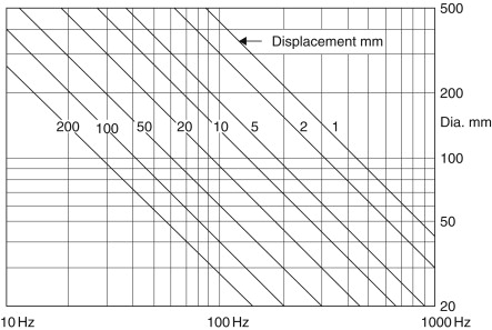
Figure 23.8 shows the necessary peak amplitude of a piston mounted in an infinite baffle to radiate one acoustic watt of sound power at various frequencies (one side only of the piston radiating). Peak amplitudes in millimeters are marked on the family of curves. For any other value of acoustic power output (P), multiply peak amplitude by VP. With an average room of 2000 ft3, a reverberation time of 1 s, and a sound pressure level of +94 dB, the total sound output power is of the order of 30 mW. To radiate this power at 50 Hz, the peak amplitude of a 250-mm radiator will be about 2 mm, while a 100-mm piston to radiate the same power would require a peak displacement of just over 13 mm. Even with “long throw” loudspeakers, it is not possible to obtain a peak-to-peak displacement of 26 mm, thus the sound power capabilities must be severely limited at low frequencies. One will often see response curves of these small speakers taken to apparently extraordinarily low frequency limits, but these are always undertaken at low power input levels.
Figure 23.8. Peak amplitude of a piston to radiate 1 W.
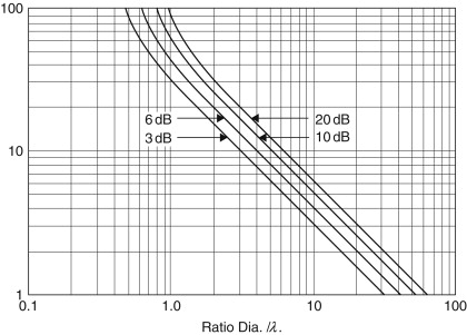
The directional radiation characteristics of a diaphragm are determined by the ratio of the wavelength of the emitted sound to the diaphragm diameter. Increasing the ratio of diaphragm diameter to wavelength decreases the angle of radiation. At frequencies in which the wavelength is greater than four times the diaphragm diameter, the radiation can be considered substantially hemispherical, but as this ratio decreases, the radiation pattern narrows. Figure 23.9 shows the polar response of a piston in terms of the ratio of diameter over wavelength. This shows the degrees off the normal axis at which the attenuation is 3, 6, 10, and 20 dB (as marked on the curves) as a function of the ratio of the piston diameter over the wavelength of the generated sound wave.
Figure 23.9. Directional radiation pattern with a circular piston in infinite baffle.
23.10. Diaphragm Profile
A practically flat disc is far removed from the theoretical “rigid piston.” With the exception of foamed plastic, the mass, for a given rigidity, will be excessive, resulting in very low efficiency, and if the cross section is reduced, the system becomes very flexible and inefficient.
Decreasing the angle from 180° increases the stiffness enormously; concomitantly the thickness can be reduced, resulting in a lighter cone for the same degree of self support. The flexure amplitudes will be reduced, but the bell modes will make an appearance. As the angle is reduced, it reaches an optimum value for level response at the transition frequency. There will be another angle for a maximum high-frequency response, resulting ultimately in peaking in the upper treble region. Continuing the reduction in angle, the high-frequency peak will be reduced, but the response above the peak will fall rapidly.
If instead of a straight-sided cone, the profile is curved, the “smoothness” of the overall response can be improved considerably: bell modes are discouraged and the on-axis high-frequency response is improved. The price charged for this facility is reduced low-frequency power handling capacity because, for a given weight, the curved cone is just not as stiff (and as strong) as the straight-sided version.
The most efficient shape at low frequencies is circular. Theoretical and experimental investigations have shown that an ellipse with a major–minor axis of 2 has an average of 7% lower radiation resistance in the useful low-frequency range than a circle of the same area; the loss becomes progressively greater as the shape departs still further from circular. The shape of the cross section or profile of the cone depends on the power handling and response desired.
For domestic loudspeaker systems, which must be cost-conscious, the loudspeaker size is limited to 150 to 200 mm and a frequency response of 100 Hz to about 7 kHz with, possibly, a 25-mm soft dome to accommodate the high frequencies. Straight-sided cones are usually employed when a good 2- to 5-kHz response is required and when reproduction above, say, 7 kHz may be undesirable. Curved cones improve the response above 6–7 kHz by providing an impedance viewed from the voice coil, which has a more uniformly high negative reactance and therefore absorbs more power from the high positive reactance due to voice coil mass seen looking back into the voice coil. This improvement is obtained at the expense of response in the 2- to 5-kHz region, a weaker cone structure, and reduced power handling in the extreme bass.
23.11. Straight-Sided Cones
The most important parameter affecting the performance of a loudspeaker is “cone flexure.” Because real materials are not infinitely rigid and have mass, the velocity of propagation through the material is finite. The cone is driven at the apex and the impulse travels outward toward the periphery where it is reflected back to the source. At particular frequencies when the distance to the edge are odd quarter wavelengths, the returning impulse will be 180° out of phase and tend to cancel; conversely, when the distance is multiples of half wavelengths they will augment—under these conditions the system can be considered as a transmission line, and theoretically (and to some extent, practically), if the outer annulus were made resistive and of the correct value, the line would be terminated and no reflections would occur [see Figure 23.10(a)].
Figure 23.10. (a) Concentric and (b) bell modes.
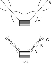

The conical diaphragm also has radial or “bell” modes of flexure. These are similar to the resonances in a bell and occur when the circumference is an integral number of wavelengths [see Figure 23.10(b)].
Obviously, both modes occur simultaneously, and at some frequencies reinforce each other and at others tend to cancel. Their main effects on performance are the “wiggles” on the response curve and transient and delay distortions. It is instructive to apply a short “tone burst”; it will be seen that at particular frequencies during the duration of the input signal the diaphragm is stationary and on cessation of the pulse it will burst into oscillation at some frequency unrelated to the driving current.
The art of diaphragm design is to minimize these deleterious effects. One method is to introduce concentric corrugations; the effect is to increase the stiffness seen by the bell modes and decrease stiffness for the concentric modes. By correctly proportioning the number, width, and wall thickness of these corrugations, the outer edges of the cone are progressively decoupled as frequency increases. This results in the “working” diameter of the diaphragm being reduced at high frequencies, thus improving the high-frequency performance.
23.12. Material
Hard impregnated or filled pressed calendered papers are used when loudness efficiency and apparent high-frequency response are important. The impregnant is usually a hard thermo-setting resin. The radiation response provides very little dissipation in direct radiator cones, hence by using paper having low internal flexural losses, the transmission line is made to have strong resonances. The transient response of this type is necessarily poor, as noncenter moving modes of the cone are unappreciably damped by the motor unit. Soft, loosely packed, felted cones are used when some loss in the high-frequency response can be tolerated and a smooth response curve with reduced transient distortion is required. The apparent loudness efficiency of high loss cones of this type is anything up to 6 dB lower than that of low loss cones of similar weight.
In an effort to overcome the intransigencies of paper cones, resort has been made to other materials. Light-weight metal (aluminum alloys, etc.) immediately springs to mind because of its stability, homogeneity, and repeatability but, because of the very low internal frictional losses, strong multiple resonances occur in the upper frequencies. A diaphragm of, say, 250 mm in diameter made from a 0.1-mm-thick aluminum alloy with a total mass of 40 g will show a “ruler” level response up to approximately 2 kHz when multiple resonances occur. These are extremely narrow band (in some cases only 1 or 2 Hz wide) with an amplitude of anything up to 40 dB and an effective Q of several hundred. Putting a low-pass filter cutting very sharply at, say, 1 kHz does not eliminate shock excitation of these resonances at low frequencies and the result is a “tinny” sound. Reducing the cone diameter and making the flare exponential reduce this effect and also places the resonant frequency a few octaves higher, but does not entirely eliminate the problem. Using foamed plastic materials (and sometimes coating the surfaces with a metal to form an effective girder structure) has met with some success. There are problems associated with the solid diaphragm in that the different finite times taken for the sound wave to travel directly from the voice coil through the material to the front and along the back edge of the diaphragm to the anulus and then across the front cause interference patterns that result in some cancellation of the emitted sound in the mid upper frequencies, say 800–1100 Hz. This effect can be mitigated by using a highly damped anulus, with the object of absorbing as much as possible of the “back wave.” Expanded polystyrene is the favorite material for these diaphragms, although expanded polyurethane has met with some success. An extension of this principle is exemplified where the diaphragm is almost the full size of the front of the cabinet (say 24×18 inches). In this case the diaphragm, even at low frequencies, does not behave as a rigid piston. The overall performance is impossible of any mathematical solution and must be largely determined experimentally, but the lower bass (because of multiple resonances) is, in the opinion of its advocates, “fruity” and “full!” It has been developed to use two or even three voice coils at strategic places on the diaphragm. For synthesized noise it is possible, but in the writer’s opinion, for “serious” music listening, it adds nuances to the music never envisaged or intended by the composer.
Vacuum-formed sheet thermoplastic resins have become very popular. Their mechanical stability is excellent, they are nonhygroscopic, and repeatability (a very important facet when mass producing units in hundreds of thousands) is several orders of magnitude better than paper cones. However, there is a price to pay: most of them contain a plasticizer, which increases the internal mechanical losses in the structure, and hence the magnitude of diaphragm resonances is reduced. However, under user conditions, dependent on electrical power input and thus operating temperature, they tend to migrate. This results in a changed cone (or dome) shape, and because the internal mechanical loss is reduced, the frequency response is changed. In extreme cases, especially with small thin diaphragms, cracking has occurred, but it must be emphasized that with a correctly designed unit operating within its specified power and frequency limits, these “plastic” diaphragms (especially those using specified grades of polypropylene) give a cost-effective efficient system.
23.13. Soft Domes
For use at medium and high frequencies, the “soft dome” system has found favor. It consists of a preformed fabric dome with integral surround and usual voice coil assembly. It is very light and its rigidity can be controlled by the amount of impregnant, but the beauty of the concept is that the damping can be adjusted by the quantity and viscosity of the “dope” applied to the dome. Responses flat ±1 dB to 20 kHz are standard, even on inexpensive mass-produced units!
23.14. Suspensions
The purpose of suspensions is to provide a known restoring force to the diaphragm/voice coil assembly and at the same time to have sufficient lateral rigidity to prevent any side-to-side movement of the system. This latter requisite is most important when it is remembered that the clearance between the voice coil and the magnet pole pieces is of the order of 0.15 mm for tweeters and 0.4 mm for 150-W woofers. The average domestic 200-mm (8-inch) loudspeaker is about 0.25 mm.
The combined stiffness of the front and rear suspensions is formulated to resonate with the total moving mass of the diaphragm/voice coil assembly and air load to the designed LF resonance. The front suspension radial width is usually about half that of the rear (in order to maximize cone diameter for a given cradle size) and it is this factor that limits the peak-to-peak displacement. Figure 23.11 shows displacement/force for a roll surround. It will be seen that the maximum linear movement is limited: it follows the familiar hysteresis curve of nonlinear dissipative systems.
Figure 23.11. Displacement relative applied force.

The annulus of the diaphragm can either be an extension of the cone material itself or, as is more usual with high-fidelity loudspeakers, be a highly compliant surround produced from cotton or man-made fibers, neoprene, or plasticized PVC. In the case of woven materials, these must be sealed and the sealant is usually used to provide some mechanical termination of the cone.
The front suspension represents a discontinuity in the diaphragm system and because it has its own mass and compliance, it is capable of a separate resonance. When this takes place it presents a very high impedance to the edge of the cone, reducing its output and causing a dip in the response. Because of its nonlinearity, it radiates considerable distortion, especially at low frequencies where the amplitude is greatest. The requirements are high flexibility and high interval losses. Probably the most successful material is plasticized PVC, using a very stable nonmigrant plasticizer such as dibutyl sebacate.
The rear suspension is the major restoring force, the radial width is usually at least twice that of the front suspension, and is a multiroll concentrically corrugated fabric disc, impregnated with a phenolic resin. The weave of the material, number of corrugations, diameter, and amount of impregnant determine the stiffness. It should provide a substantially linear restoring force over the designed maximum amplitude of displacement. The whole structure behaves mechanically as a series resonant circuit. The mass is determined by the weight of the cone, voice coil, and former, and the stiffness by the combined effects of the rear suspension and the annulus, the Q of the circuit being determined almost wholly by the losses of the restoring force.
23.15. Voice Coil
The dimensions of a voice coil are determined primarily by the rated power handling of the loudspeaker. It must be emphasized that with direct radiators, 95–99% of the input electrical power is dissipated in the form of heat; even with the most efficient horn loaded units a minimum of 50% is used for heating purposes only. Figure 23.12 shows voice coil temperature versus input power. The limiting temperature is set by:
- Maximum temperature rating of the former: 100°C for paper-based materials; 150°C for “Nomex,” which is an aromatic polyamide; 250°C for polyimide;
- Temperature rating of the wire enamel: maximum 220°C for ML insulation, down to 110°C for self-bonding and self-fluxing wires;
- Adhesive; from 110°C for cyanoacrylic to 250°C for those with polyimide base; and
- Mechanical expansion of the voice coil diameter at elevated temperatures.
Figure 23.12. Voice coil temperature versus input power (300 Hz).

Fortunately, there is in-built semiprotection for the assembly, namely temperature coefficient of resistance of the wire, which is +0.4% for a 1°C rise in temperature! Thus at a temperature of +250°C above ambient, the voice coil resistance has doubled, and for a constant voltage input (which is the norm for modern amplifiers), the indicated power E2/Rnom is twice the actual power. Note that Rnom is the manufacturer’s specified resistance and is, or should be, the value at the series resonant frequency Rco where the input impedance is minimum and resistive.
23.16. Moving Coil Loudspeaker
Figure 23.13 shows the structural features of a moving coil direct radiator loudspeaker, and for purposes of analysis it will be convenient to divide it into two parts: the “motor” or “drive” unit and the acoustic radiator, or diaphragm, described earlier.
Figure 23.13. Moving coil loudspeaker cone, suspensions, and voice coil assembly.

The driving system consists of a solenoid situated in a radial magnetic field. It is free (within certain restraints) to move axially (see Figure 23.14). When a current is passed through the coil, a magnetic field will be generated, with the magnitude being directly proportional to //, and this will react with the steady field of the permanent magnet and a mechanical force will be developed that will tend to move the coil axially, either inward or outward depending on the direction of the current. The magnitude of this force is (23.24)
![]() where B is flux density in Webers/m2,/is conductor length in meters, and/is current in amperes.
where B is flux density in Webers/m2,/is conductor length in meters, and/is current in amperes.
Figure 23.14. Moving coil motor element.
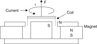
It should be noted that l refers only to that portion of the coil situated in the magnetic field. As shown later, to reduce distortion the coil is often longer than the working magnetic field defined by the gap dimensions.
If the coil is free to move, its velocity will be determined by the applied force F and the mechanical impedance Zm. The mechanical impedance Zm will be a function of total mass (Lm) of the system, that is, voice coil and former, diaphragm, air loading, etc., resistance Rm due to losses in the suspension and radiation, and total stiffness (1/Cm) due to the restoring force.
Using normal circuit theory, the impedance will be(23.25)
![]() This represents a simple series resonant circuit shown in Figure 23.15. While one can predict resonant frequency from lumped mechanical constants, the analysis must be carried several stages further
to arrive at the correct transfer characteristic from electrical input to sound output in practical loudspeaker design.
This represents a simple series resonant circuit shown in Figure 23.15. While one can predict resonant frequency from lumped mechanical constants, the analysis must be carried several stages further
to arrive at the correct transfer characteristic from electrical input to sound output in practical loudspeaker design.
Figure 23.15. Analogue of lumped mechanical constants.

Figure 23.16 takes the analogue a stage further:
- Lmd, Cmd, and Rmd are the mechanical components of diaphragm, voice coil, and suspension.
- Lma, Rma: mechanical impedance components of air load.
- Zme: mechanical impedance due to electrical system.
- Zma: mechanical impedance due to air load on rear of cone.
- Zmx: normally zero, but see motional impedance.
Figure 23.16. Analogue referred to mechanical side.

23.17. Motional Impedance
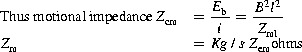
The moving coil system is a reversible transducer, a current through the coil will produce a force, and the resultant velocity of the coil will produce an EMF. This voltage will be a function of velocity, conductor length, and magnetic field strength; thus if an external EMF is applied to the coil the resultant motion will generate a back EMF (180° out of phase), which will tend to counteract the forward current flow, thus increasing the electrical impedance. This is “motional impedance.”
If the motion of the system can be prevented by applying an infinite mechanical impedance (Zmx in Figure 23.16), there will be no back EMF and the electrical impedance will be only the voice coil resistance and inductance (blocked impedance). Reducing the mechanical impedance (reducing mass and resistance and increasing compliance) will result in an increase in velocity and the motional impedance will be increased. Intuitively, this indicates that motional impedance will be proportional to Bl and an inverse function of the mechanical impedance. The common factor is the velocity of motion.(23.26)
![]() (23.27)
(23.27)
![]() (23.28)
(23.28)
 from Equations (23.27) and (23.28)(23.29)
 (23.30)
![]() where Yem is electrical admittance due to mechanical circuit
where Yem is electrical admittance due to mechanical circuit
 (23.31)
 (23.32)
![]() (23.33)
(23.33)
![]() (23.34)
(23.34)
![]() where Rm is Kg/s (mechanical ohms), Lm is Kg, and Cm is meters/Newton and, by inversion,(23.35)
where Rm is Kg/s (mechanical ohms), Lm is Kg, and Cm is meters/Newton and, by inversion,(23.35)
![]() (23.36)
(23.36)
![]() (23.37)
(23.37)
![]() It will be noted that in the analogue inductance (mass) in the mechanical circuit will become a capacitance in the electrical
circuit, etc.
It will be noted that in the analogue inductance (mass) in the mechanical circuit will become a capacitance in the electrical
circuit, etc.
At mechanical resonance(23.38)
and the mechanical impedance Zm will have a minimum value=Rm. The velocity will be maximum, thus the back EMF and motional impedance will be maximum, indicating a parallel resonance. It will be seen that series components in the mechanical circuit appear as parallel components in the electrical side and vice versa.
23.17.1. Analogue Models
We can now assemble the various parameters to produce a basic analogue for a loudspeaker. Figure 23.17 shows the low-frequency analogue referred to the mechanical side. The quantity fc represents the total force acting in the equivalent circuit to produce the voice coil velocity uc:(23.39)
![]() Let us divide the frequency region into five parts and treat each part separately by simplifying the circuit in Figure 23.18 to correspond to that part alone. In region A, where the loudspeaker is stiffness controlled, the power output increases
as the fourth power of frequency, or 12 dB/octave. In region B, at resonance frequency 0)o the power output is determined by the total resistance because Xm passes through zero. For large values of Bl and small values of Rc, the total circuit resistance becomes sufficiently large so that the resonance is more than critically damped. The sound
pressure will increase linearly with frequency (+6 dB/octave). In region C, the power output (and sound pressure) approaches
a constant value, provided that the circuit impedance approximates a pure mass reactance. That is to say, RMR and Xm2 both increase as the square of the frequency.
Let us divide the frequency region into five parts and treat each part separately by simplifying the circuit in Figure 23.18 to correspond to that part alone. In region A, where the loudspeaker is stiffness controlled, the power output increases
as the fourth power of frequency, or 12 dB/octave. In region B, at resonance frequency 0)o the power output is determined by the total resistance because Xm passes through zero. For large values of Bl and small values of Rc, the total circuit resistance becomes sufficiently large so that the resonance is more than critically damped. The sound
pressure will increase linearly with frequency (+6 dB/octave). In region C, the power output (and sound pressure) approaches
a constant value, provided that the circuit impedance approximates a pure mass reactance. That is to say, RMR and Xm2 both increase as the square of the frequency.
Figure 23.17. A low-frequency mechanical analogue.

Figure 23.18. Simplified circuit, valid over restricted frequency ranges: (a) very low frequencies, (b) at principal resonance frequency ω0, (c) above principal resonance frequency, (d) at second resonance frequency, and (e) at high frequencies.


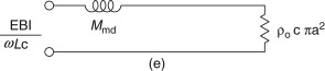
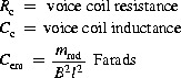
Figure 23.17 shows that the inductance of the voice coil is reflected into the mechanical circuit as a compliance [very much smaller than Cms, which will resonate with the total mass at a midfrequency (usually 150–700 Hz); see Figure 23.18]. At this frequency, the total electrical impedance is resistive, has the lowest absolute value, is the value that is (or should be) quoted as the rated impedance in the manufacturer’s specification, and corresponds to (d) in Figure 23.18.
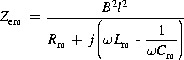
Instead of referring all the parameters to mechanical mesh, it is sometimes more convenient to refer to the electrical input (see Figure 23.19) in which(23.40)
![]() (23.42)
(23.42)
![]() Rc and Lc are the “blocked” impedance values and not the DC resistance and inductance measured in “air.”(23.43)
Rc and Lc are the “blocked” impedance values and not the DC resistance and inductance measured in “air.”(23.43)
![]() (23.44)
(23.44)
![]() where a is diaphragm radius and Sd is diaphragm area.
where a is diaphragm radius and Sd is diaphragm area.
Figure 23.19. Analogue referred to electrical input.

It should be noted that the factor 8a/π in Equation (23.43) is actually the “end correction” used to describe the accession to inertia acting on one side only of a rigid piston of radius ‘a’ vibrating in an infinite baffle. The air loading on the back side of the diaphragm is determined by the loading presented by the enclosure.
Figure 23.20 shows the impedance of a 300-mm (12-inch) loudspeaker in an 85-liter enclosure (3 ft3). It will be seen that the modulus of impedance rises to 125 ohms at the mechanical resonant frequency of 55 Hz, drops to 8 ohms at the series resonance, and rises to 40 ohms at 10 kHz. Of equal interest is the reactive component: below the first resonance an inductive reactance is presented to generator (rising to infinity at resonance), while between the two resonances a capacitive reactance is presented. At 100 Hz the effective capacitance is about 90 μF, and at that frequency the phase angle is 45°. Above the second resonance the impedance rises slowly. It will be seen that the design of a successful moving coil loudspeaker owes as much to art as science (Figures 23.21 and 23.22). CAD can and does simplify much of the detail work, but after the basic design parameters (diaphragm size, magnetic field strength, conductor length, etc.) have been calculated, the nub of the problem is what diaphragm material, adhesives, cradle material and shape, and so on to use—the art of loudspeaker design is 5% inspiration, 95% perspiration, plus the essential compromise.
Figure 23.20. Complex impedance of moving coil loudspeaker.
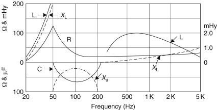
Figure 23.21. A 25-mm OEM soft-dome tweeter.
Figure 23.22. A 200-mm OEM bass midrange loudspeaker drive unit.
