Chapter | fourteen
Loudness Metering
CHAPTER OUTLINE
Model 737 Soundtrack Loudness Meter – Leq(m)
LM100 Broadcast Loudness Meter
Loudness is defined as the subjectively assessed level of sound. The task of an instrument named a loudness meter is more or less to emulate human hearing. The problem, however, is that the hearing and the assessment of sound to some degree is individual from person to person. Hence a true loudness meter is very difficult to define. Level, dynamic range, frequency range, the direction of received sound, and the character of the sound itself will have an effect on the perceived loudness. Further it is not possible to express the loudness of an electrical signal; it is the acoustic sound received and perceived by the listener that should be the basis for the measurement or calculation of loudness. So in reality the truth is impossible to reach. It is rather a question of defining a system that exhibits minimum error, a system that is satisfactory to most listeners.
For years there have been systems striving to measure loudness, the Zwicker method being the most significant. This method is still valid regarding humans’ assessment of noise. Recently, intensive research has taken place trying to define the optimum system for audio production and broadcast. This has led to new recommendations (ITU-R BS.1770, EBU R 128) that may develop further in the future. This chapter tries to provide an overview of the most important existing and new possibilities for loudness metering. Most attention is paid to the EBU meter, as this must be regarded as the state-of-the-art.
There are a number of loudness measuring systems that have been in use for audio production and broadcast for a long time. Since the Standard Volume Indicator or VU meter was developed and standardized, alternative ideas have found their way into audio production facilities.
DORROUGH LOUDNESS METER
The loudness meters from Dorrough Electronics have been widely used both in music production and broadcast since their introduction in the early 1970s. From that time these meters have been manufactured as standalone units for analog and digital audio or as plug-ins for digital audio workstations (DAWs).
The meters essentially simultaneously display the instantaneous peak level of the signal as well as the average program level on the LED scale, which for basic use has a linear range of 40 dB. The difference between the readings expresses the “density” of the program. Each channel is measured individually.
The peak acquisition period is 10 ms to full scale (measured with a 25 kHz sine input). The peak decay period is 180 ms, from full scale to all LEDs off. The loudness impression is derived from an average reading of the program signal. The time constant for the average reading is 600 ms.
Most systems in the line facilitate two-channel/stereo signals. Inter channel phase relations can be monitored. The reading can be changed from LR to MS (Sum/Diff modes). Special automatic zooming of scales for calibration is provided (Dorrough Window Expansion Mode). Various alarms can also be set (e.g., for over/under level and for phase errors).
DOLBY METERS
Dolby Labs is a major provider of audio equipment and systems primarily to the film industry and broadcast. Over the years several Dolby inventions have become de facto standards. Dolby metering systems have been developed to meet the demands from the industry.

FIGURE 14.1 Dorrough Loudness Meters provide simultaneously a reading of the peak and the average program level.
Model 737 Soundtrack Loudness Meter – Leq(m)
This meter has been developed for the measurement of Leq(m), primarily on film (see Chapter 10 on Determination of Loudness). While this unit has actually been withdrawn, a large number of Model 737 meters are still in service, as Leq(m) has become a standard for the measurement of commercials and trailers in many countries. It should be mentioned that the measure is more annoyance than loudness.
LM100 Broadcast Loudness Meter
The Dolby LM100 Broadcast Loudness Meter was developed as a tool for measuring the subjective loudness of dialog within broadcast programming. The background for this is the fact that dialog can be regarded as the “anchor element” of a program; lining up dialog levels provides a better equality of loudness within and between programs.
The LM100 employs the proprietary technology Dialogue Intelligence™ to measure the perceived loudness of dialog in a complex program. The early versions utilized Leq(A) for this measurement. However, the newer versions also have implemented the ITU-R BS.1770 algorithm as well (discussed further later in the chapter). Further, the instrument can determine the unweighted peak and a range of other information about the signal. The unit can simultaneously display the incoming dialog normalization (dialnorm, see Chapter 17 on Dynamic Scales) value of a Dolby Digital program or any program within a Dolby E bitstream for direct comparison with the actual measured value.
A set of user-definable alarms and monitoring functions can inform an operator of input loss, signal clipping, over modulation (LM100-NTSC version), high or low signal levels, silence, and incorrectly set dialnorm values.
Dolby Media Meter 2
The Dolby Media Meter is a software tool that measures loudness in programming for broadcast, packaged media, cinema trailers, VOD, and games. Beside the features found in the LM100 the Media Meter can perform the measurement of Leq(m). This software meter should be regarded as a substitute for the Model 737. The Dolby Media Meter 2 runs on all major platforms.

FIGURE 14.2 An example of the display read out on the Dolby LM100.
ITU-R BS.1771 (2006)
With the digital age entering broadcast the International Telecommunications Union realized that a number of problems in transmission needed solutions. A larger dynamic range was now available. The transmission would cover formats from mono to surround. Downstream conversion to lower bit rates would create alteration of peak levels. However, the most serious problem was the different levels perceived by the listener when zapping between the channels or when the same channel was changing between different content: the loudness problem.
A workgroup facilitated the psycho-acoustic testing of different already available and new loudness meters and algorithms. The “best fit” for real audio mono samples proved to be a Leq of the RLB-weighted signal. After reaching this conclusion, the work was expanded to include the evaluation of program contents in stereo and surround as well. This involved a pre-filter to compensate for the presence of the head and a gain to surround channels due to the special awareness effect of sound coming from the rear. The total weighting of the signal (frequency and level) got the name k-weighting (“k” being an available symbol for this purpose). The algorithms are defined in the recommendation ITU-R BS.1770 from 2006.
The ITU Loudness Meter
The advantage of the “winning” algorithm is that it is not proprietary to any private company and the meters can be manufactured by everybody. The meter specifications are explained in ITU-R BS.1771: Requirements for loudness and true-peak indication meters (2006).
The introduction of the Loudness Unit, LU, was a consequence of the practical implementation of this meter. In this standard the LU is a relative unit. The absolute loudness level at the reference indication can be defined elsewhere. The absolute level of the program loudness is defined by LKFS, meaning the level of the k-weighted signal with reference to full scale. Thus, the reference indication or the target loudness (0 LU) at an absolute level must be stated in LKFS.
Additionally, the absolute peak level (true peak) had to be considered. In digital systems oversampling must be used. At four times oversampling the worst case under-read is in the range of 0.6 dB. At eight times oversampling the worst case under-read is in the range of 0.15 dB. For the purpose of the standard, four times oversampling was chosen for the true peak reading.
DEFINITIONS
Loudness Unit (LU) The loudness unit is the scale unit of the loudness meter.The value of the program in loudness units represents the loss or gain (dB) thatis required to bring the program to 0 LU; e.g., a program that reads e10 LU willrequire 10 dB of gain to bring that program up to a reading of 0 LU.
Type I electronic display Electronic display with resolution of one or more segments per loudness unit.
Type II electronic display Electronic display with resolution of one segment per three loudness units.
The following features are required to fulfill the recommendation:
| General requirements | The loudness display reading must not vary by more than 0.5 Loudness Units when the signal polarity is reversed. |
| Common requirements for program loudness displays | The loudness display shall be calibrated in loudness units. Loudness of a stereo or multichannel sound program shall be shown by a single display. (This does not prevent meters from also displaying individual channel loudness.) |
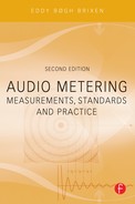
| Requirements for program loudness display – mechanical type | A mechanical loudness meter display shall have a nonlinearity of not more than 1% of full-scale deflection over its operating range. |
| Display requirements – Optional peak level indicator on loudness meter | The threshold for overload indication shall be – 2 dB re full scale digital input. The overload indicator shall activate if the true-peak digital audio level exceeds the threshold. Once the indicator light is activated it shall remain activated for at least 150 ms after the signal has fallen below the threshold. |
In addition to these mandatory requirements a number of optional facilities are proposed. One of these is that the loudness meter may have at least two operating modes: F mode (fast) and I mode (integrating). Further, the integrating mode may have a start/stop button or switch.
TC ELECTRONIC LM5/LM5D
TC Electronic has played an active part in the work for establishing standards for loudness measures. The ideas and research behind the LM5 software-based meter has impacted the EBU recommendation and it is expected that EBU terminology will be reflected in future updates of the meter. The initial versions of the meter operate with LU (Loudness Units as per ITU-R BS.1770), and LFS (loudness with reference to full scale, comparable to LKFS or LUFS).
The LM5 has the basic circular-shaped graphic. Some of the descriptors displayed by the meter are Short-Term Loudness (outer ring) and Loudness History (radar). Additionally, the true peak levels aredisplayed.
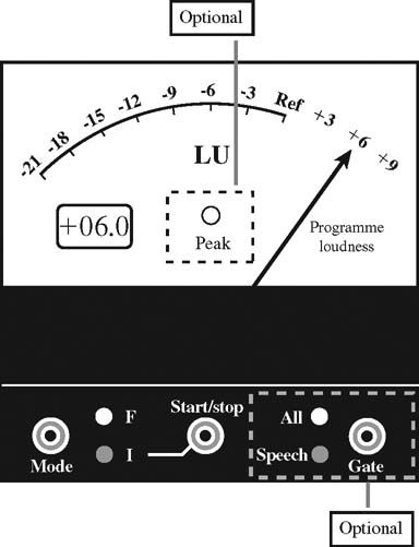
FIGURE 14.3 Example of program loudness display, mechanical type given by ITU-R BS.1771.

FIGURE 14.4 Example of program loudness level display, optoelectronic Type I (left) and Type II (right) given by ITU-R BS.1771.

FIGURE 14.5 This display, of the ITU-R loudness meter developed at CRC, is the result of CRC’s collaboration with CBC/Radio-Canada. The scale can display either LKFS or LU.
The LM5D displays long-term statistical descriptors that describe an entire program, film, or music track. Center of Gravity (CoG) indicates the average loudness of a program, and is directly operational. If, for instance, a broadcast station is operated at an average loudness level of –23 LFS, and a commercial has its Center of Gravity measured at –19.5 LFS, the program should be attenuated by 3.5 dB before transmission for a best fit.
Consistency indicates the loudness variations inside a program. Center of Gravity ranges from –80 LFS to +12 LFS, while Consistency ranges from –40 to 0 LU.

FIGURE 14.6 The characteristic radar display on an LM5 from TC Electronic. The speed of the radar can be set.
EBU R 128 LOUDNESS METERING
The European Broadcast Union wanted to implement the loudness measure already accepted by the ITU. In addition to this a gating technique was considered as well as a new descriptor called “Loudness Range.” The new practices should replace the existing standard for PPM and at the same time exploit the dynamic range provided by a digital system.
EBU R 128 was published in autumn 2010. This recommendation introduced three descriptors: Program Loudness, Loudness Range, and Maximum True Peak Level. It also defined target levels as well as specifications for a meter to display the measures.
Program Loudness
Program Loudness is determined using k-weighting (as per ITU-R BS.1770) and averaging over the total length of the program. However, this includes a gating 8 LU below the target level. Whenever the program is below this gating level the loudness calculation is paused. (See Chapter 10 on Determination of Loudness.)
Loudness Range (LRA)
Loudness Range (LRA) is defined in EBU Technical Document 3342. Originally this descriptor was developed by TC Electronic (and named “Consistency”). LRA is defined as the difference between the estimates of the 10th and the 95th percentiles of the distribution. The lower percentile of 10%, can, for example, prevent the fade-out of a music track from dominating the Loudness Range. The upper percentile of 95% ensures that a single unusually loud sound, such as a gunshot in a movie, cannot by itself be responsible for a large Loudness Range.
The computation of the Loudness Range is based on the statistical distribution of measured loudness using a sliding analysis window with a length of 3 seconds for integration. An overlap between consecutive analysis windows is used to retain precision of the measurement of shorter programs. A minimum block overlap of 66% (i.e., minimum 2 s of overlap) between consecutive analysis windows is required. By doing this, a short but very loud event will not affect the Loudness Range of a longer segment. Similarly, the fade-out at the end of a music track, for example, will not increase the Loudness Range noticeably. Specifically, the range of the distribution of loudness levels is determined by estimating the difference between a low and a high percentile of the distribution.
The Loudness Range also employs a gating method. The relative threshold is set to a level of –20 LU relative to the absolute gated loudness level. Certain types of programs may be, overall, very consistent in loudness, but have some sections with very low loudness, such as only the background environment. If the Loudness Range did not use gating, programs like that would (incorrectly) get quite a high Loudness Range measurement.
The purpose of the absolute threshold gate is to make the conversion from the relative threshold to an absolute level robust against longer periods of silence or low-level background noise. The absolute threshold is set to –70 LUFS, because no relevant signals are generally found below this loudness level.
The optimum LRA will be program dependent.
Maximum True Peak Level
The maximum true peak level is defined to –1 dBTP measured with a meter compliant with both ITU-R BS.1770 and EBU Technical Document 3341. Hence four times oversampling is applied to ensure a correct reading.
EBU Mode Meter
To ensure that the different descriptors are measured and reported correctly and not mixed up with other measures, any meter that measures according to R 128 must have an “EBU Mode.” When set in this mode the meter complies with EBU Technical Document 3341. The EBU Mode does not concern the graphical/ UI details or the implementation of a meter.
THE THREE TIME SCALES
There are three time scales, represented as follows:
- The shortest time scale is called “momentary,” abbreviated “M.”
- The intermediate time scale is called “short-term,” abbreviated “S.”
- The program- or segment-wise time scale is called “integrated,” abbreviated “I.”
The loudness meter should be able to display the maximum value of the “momentary loudness.” This maximum value is reset when the integrated loudness measurement is reset.
INTEGRATION TIMES AND METHODS, METER BALLISTICS
In all cases the loudness measurement is performed as specified in ITU-R BS.1770. The measurement parameters for EBU Mode are the following:
- The momentary loudness measurement uses a sliding rectangular time window of length 0.4 s. The measurement is not gated.
- The short-term loudness measurement uses a sliding rectangular time window of length 3 s. The measurement is not gated. The update rate for “live meters” shall be at least 10 Hz.
- The integrated loudness measurement uses gating as described in ITU-R BS.1770. The update rate for live meters shall be at least 1 Hz.
The EBU Mode loudness meter provides functionality that enables the user to at least start/pause/continue the measurement of integrated loudness and Loudness Range simultaneously, that is, switch the meter between “running” and “standby” states; and reset the measurement of integrated loudness and Loudness Range simultaneously, regardless of whether the meter is in the “running” or “standby” state.
THE MEASUREMENT GATE
The “integrated loudness” should be measured using the gating function described earlier.
LOUDNESS RANGE (LRA) DESCRIPTOR
An EBU Mode meter should compute the Loudness Range (see above).
UNITS
A relative measurement, such as relative to a reference level or a range: LK = xx.x LU
An absolute measurement: LK = xx.x LUFS
The “L” in “LK” indicates loudness level; the “K” indicates the frequency weighting used.
TRUE PEAK MEASUREMENT
True peak is measured using four times oversampling.
SCALES AND RANGES
The display of an EBU Mode meter may be simply numerical, or an indication on a scale.
The scale used may either be an absolute scale, using the LUFS unit, or alternatively the zero point may be mapped to some other value, such as the target loudness level (as in ITU-R BS.1771). In the latter case the LU unit should be used, indicating a relative scale. For an EBU Mode meter, the target loudness level shall be −23 LUFS = 0 LU (as defined in EBU R 128). An EBU Mode meter should offer both the relative and the absolute scale.
FIGURE 14.7 EBU Mode scales. The recommendation R 128 does not specify any specific layout. However, if in the EBU mode, these scales should be available.
The location of the target/reference loudness level should remain the same, regardless of whether an absolute or relative scale is displayed.
An EBU Mode meter should offer two scales, selectable by the user:
- Range −18.0 LU to +9.0 LU (−41.0 LUFS to −14.0 LUFS), named the “EBU +9 scale”
- Range −36.0 LU to +18.0 LU (−59.0 LUFS to −5.0 LUFS), named the “EBU +18 scale”
- The “EBU +9 scale” should be used by default.
Bibliography
EBU Technical Recommendation R 128 Loudness normalisation and permitted maximumlevel of audio signals (2010).
EBU Technical Document 3341, Loudness Metering. ‘EBU Mode’ metering to supplement Loudness normalisation according to EBU Technical Document R 128 (2010).
EBU Technical Document 3342 (2010), Loudness Range. A descriptor to supplement Loudness normalization according to EBU Technical Recommendation R 128.
Itu-R BS. 1770. Algorithms to measure audio programme loudness and true peak audio level (2006).
Itu-R BS. 1771. Requirements for loudness and true-peak indicating meters (2006).
TC Electronic: Manual for LM5 & LM5D Loudness Radar Meters (2010).