
Chapter | twenty-three
Digital Interface
CHAPTER OUTLINE
IEC 60958-3 – 2006 Consumer Applications
When digital information is to be transferred from one device to another, a protocol is used to ensure that both the transmitter and the receiver are in agreement on which bit means what. In addition, the physical connection is specified for connecting the two devices. In doing this, an interface has been defined.
PROTOCOL
Each sample, which is described by a number of bits arranged in a sequence, can have a number of extra bits (metadata) appended to it that give information associated with the sample concerned. It could be information about which channel the signal belongs to, whether pre-emphasis has been applied on the analog signal, data on the actual sampling frequency, or a lot of other useful information. Samples and extra information are combined into frames. The protocol defines in part the structure of the individual frames and the combining of frames into blocks of data.
PHYSICAL CONNECTION
The digital information is transferred in the form of a voltage signal, a current signal, or as light impulses on a fiber optic cable. The individual standards define what method or methods are used.
Even though it is sound that is being transferred, the frequency content in such a connection will immediately reach up to several MHz. Hence sound signals transferred as digital signals should always be treated as RF.
AES3
The most widely used interfaces for audio were originally initiated and standardized by the Audio Engineering Society and the European Broadcast Union, and hence used the names of both of these organizations. However, the AES has taken over the maintenance of this standard, so the name has just become “AES3.” It is a standard that is constantly under development as new options in digital audio are brought to the market.
The format is serial (i.e., even though it contains two channels, it can be run on one wire). During the transmission, a sample from the first channel is transferred, followed by a sample from the second channel and so on.
The physical connection is comprised of a balanced 110 ohm cable with XLR connectors. The level is 2–7 Vpp (peak to peak). However, the signal can be read all the way down to 200 mVpp. Transport lines other than balanced lines may be applicable.
The core of the data portion for AES3-2 consists of 20 sound bits, and 4 extra bits (aux). These 4 extra bits have gradually come to always be used for sound, so regardless of how many bits are used in the sampling, 24 bits per sample are transferred. For example, if 16 significant bits are involved (as in the CD format) then bits 17–24 will simply be set to the value “0.” Each sample (from either the right or the left channel) is placed into a 32-bit sub-frame.
PREAMBLE AND V, U, C, AND P
The eight “surplus” bits in each sub-frame are used for synchronization and extra information. The first four bits comprise a preamble, which indicates which channel the current frame represents or whether it is the first sub-frame in a block. The last four bits contain extra information that can say something about the signal that is being transmitted. This information is divided up into four individual bits, which are designated V, U, C, and P.

FIGURE 23.1 AES sub-frame, “packaging” of each sample. Each sub-frame begins with a preamble to help with the synchronization. Each sub-frame ends with four bits containing useful information.
V stands for Validity. This bit indicates whether the associated sample is in order. P stands for Parity. This parity bit is set so that an even number of 1s is always attained in each sub-frame. If a check on the Parity bit fails, the Validity bit is reset to indicate possible corruption in the sub-frame data.
C (Channel status) transmits information about the signal itself and U (User bit) can, as the name implies, be used by the user. C and U are collected on a running basis into 8-bit bytes.
FRAMES AND BLOCKS
Two sub-frames together comprise an entire frame of 64 bits (2$32) in total. In audio, this will normally be one sub-frame with data from the left channel and one sub-frame with data from the right channel. If the sampling frequency is for example 48 kHz, then it means that 64 bits must be transferred 48,000 times per second. This results in a bit stream of a good 3 Mbps (megabits per second). In connection with the expansion of the standard for use with higher rate sampling (88.2 or 96 kHz), two sub-frames can be used to contain samples from a single channel.
A block is formed from 192 pairs of samples or frames. At a sampling frequency of 48 kHz this results in 250 blocks per second. A byte is comprised of 8 bits. In each block, 2⋅24 (2⋅(192/8)) channel status bytes, and the same number of user-defined bytes, can be formed by left channel user data and right channel user data, respectively. Sub-frame 0–7 forms the first byte, 8–15 forms byte number two, etc. Each byte in a block has its own significance. With 250 blocks and thus that many bytes per second (at fs = 48 kHz), a great deal of extra information can be transferred along with the sound.
CHANNEL STATUS
The information that is contained in channel status can be used to indicate what the actual bit stream consists of and where the individual sample belongs, and it can also provide a full time code. The data contained may be protected with its own error correction code (CRC).
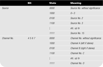
As mentioned earlier, 24 bytes can be established within one block. Of these, we will only look at the first five. This information is defined in the AES3 standard. While the AES3 standard is the most comprehensive protocol, other interface protocols use similar information.
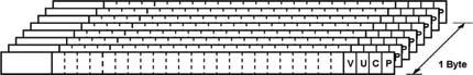
FIGURE 23.2 AES: For every 8 sub-frames, one byte can be formed. One block contains 192 frames (2⋅192 sub-frames).
Status Byte 0
It is here the most significant difference is found between the professional and consumer versions. Depending on the value of the first bit, the channel status will have a different meaning. The AES deals in principle only with the professional version. The consumer information lies in the protocol for IEC 60958, also known as S/PDIF.
TABLE 23.1 AES3, status byte 0.

Status Byte 1
This byte contains information on the relationship between the audio signals in the two channels. After higher-rate sampling became an option, an indication was also added for the relationship between sub-frames.
TABLE 23.2 AES3, status byte 1.

Status Byte 2
Here information is found on auxiliary bits, word length, and alignment level.
TABLE 23.3 AES3, status byte 2.

Status Byte 3
In multi-channel mode this byte can indicate which channel is involved.
Status Byte 4
The last part of this byte was put into use for the indication of sampling frequencies that were introduced after the original standard ones.
TABLE 23.4 AES3, status byte 4.

AES3 AS A GENERAL FORMAT
Regarded as an interface, AES3 can also be used as a general transport format, for example for bit-reduced multi-channel sound. The interface is used for example for Dolby E, which is a standard for bit-reduced sound in six channels with accompanying metadata. Similar possibilities exist for MPEG formats.

FIGURE 23.3 Significant information gathered from channel status and made available on the screen of the instrument. Among other things, one can derive that this concerns professional/two-channel audio/48 kHz/24 bit/without emphasis/no time code.
BI-PHASE MODULATION
Before the digital bit stream in the AES3 signal is transmitted, it is subjected to bi-phase modulation. This is the same coding as is used in SMPTE time codes. With bi-phase modulation, a shift is performed (from 0 to 1 or vice versa) for each new bit in the signal. In addition, a shift occurs each time the bit value is “1.” The advantages of bi-phase modulation include that the signal is free of DC, independent of connecting polarity, and in general self-clocking.
IEC 60958-3 – 2006 CONSUMER APPLICATIONS
IEC 60958-3, formerly known as the Sony Philips Digital Interface, or just S/ PDIF, was defined as a consumer format. The structure of the data stream is the same as in AES3. There are certain differences in that the format also contains the transmission of four-channel usage. Another significant point where it differs is copy protection (copy-prohibited).
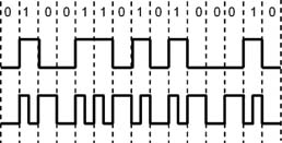
FIGURE 23.4Bi-phase modulation. Top: Digital information. Bottom: Same signal, butbi-phase modulated.
The physical connection deviates from AES3, in that a 75 ohm unbalanced coax cable with RCA-phono jacks is used. The electrical level ought to be above 1 Vpp; however, values down to 400 mVpp can be read. In practice, this means that there are abundant opportunities for S/PDIF and AES3 to be able to understand each other. S/PDIF can also be run on fiber optic cables.
Channel Status
The structure of the bit format is, as mentioned earlier, comparable with AES3. The difference is indicated in channel status byte 0. If the value is 0, then the subsequent bits and bytes in channel status will have meanings that differ from AES3.
Status Byte 0
The general information on the audio format is placed here.
TABLE 23.5 IEC 60958-3, status byte 0.

Status Byte 1
This byte is reserved for information on the type of device that generated the signal. The original categories encompassed: general, CD, PCM adapter, or DAT. The specifications have later been extended in step with the widespread use of digital media.
TABLE 23.6 IEC 60958-3, status byte 1.

Status Byte 2
TABLE 23.7 IEC 60958-3, status byte 0.
OTHER INTERFACE STANDARDS
AES3 has been the basis for special applications. AES42 is a standard for digital microphones. It is very much like AES3; however, metadata bytes are defined for signaling the make, type, and settings, etc. In the SDI (serial digital video interface) four AES3 pairs are embedded for audio purposes.
There are of course other important interfaces besides AES3 and the standards closely related to it. The formats can differ from each other by their primary purpose, the number of channels, the quantity of metadata, etc.
Bibliography
AES3-1-2009: AES standard for digital audio – Digital input-output interfacing – Serial transmission format for two-channel linearly-represented digital audio data – Part 1: Audio Content.
AES3-2-2009: AES standard for digital audio – Digital input-output interfacing – Serial transmission format for two-channel linearly-represented digital audio data – Part 2: Metadata and Subcode.
AES3-3-2009: AES standard for digital audio – Digital input-output interfacing – Serial transmission format for two-channel linearly-represented digital audio data – Part 3: Transport.
AES3-4-2009: AES standard for digital audio – AES standard for digital audio – Digital input-output interfacing – Serial transmission format for two-channel linearly-represented digital audio data – Part 4: Physical and electrical.
AES42 – 2006: AES standard for acoustics – Digital interface for microphones.
AES47 – 2006: AES standard for digital audio – Digital input-output interfacing – Transmission of digital audio over asynchronous transfer mode (ATM) networks.
AES47-Am1-2008: Amendment 1 to AES47 – AES standard for digital audio – Digital input-output interfacing – Transmission of digital audio over asynchronous transfer mode (ATM) networks.
AES50 – 2005: AES standard for digital audio engineering – High-resolution multi-channel audio interconnection.
AES51 – 2006: AES standard for digital audio – Digital input-output interfacing – Transmission of ATM cells over Ethernet physical layer.
AES58 – 2008: AES standard for digital audio – Audio applications of networks – Application of IEC 61883-6 32-bit generic data.
AES-10id-2005: AES information document for digital audio engineering – Engineering guidelines for the multichannel audio digital interface, AES10 (MADI).