Chapter | fifteen
Calibration of Level Meters
CHAPTER OUTLINE
Attention must be paid to the fact that a level meter is a measuring instrument. And if a measuring instrument is not calibrated, what can it then be used to measure?
CONSTANT TONE
An analog instrument is calibrated first and foremost using a constant pure tone. In many cases the frequency is chosen to be 1 kHz. However, that will depend on the type of meter or instrument you want to calibrate. Sound level meters or any measuring device related to acoustic measurements can be calibrated using a constant continuous 1 kHz pure tone because at this frequency the weighting filters (like IEC A) are neutral. Many program meters will accept or require 1 kHz as well for checking the constant continuous reading. In loudness meters (ITU/EBU) one should be aware that 1 kHz actually lies on the slope of the pre-filter. Hence very narrow tolerances are needed in the filter design.
If you are in possession of a high precision digital RMS voltmeter, you can then measure the magnitude of the signal for the comparison.
TONE BURST
The integration time – or perhaps more correctly – the reaction time of an instrument is tested using a tone burst generator. The practical calibration is usually defined by the time it takes the meter to reach a given percentage of the reference level. A tone burst generator can supply a tone for a welldefined period of time, for example 5 ms or 300 ms, and repeat at a fixed interval, for example 1.5 s or 300 ms. It should be noted that the frequency generally is 5 kHz in order to have a sufficient number of periods to comprise a tone burst. If the frequency is too low or the burst does not contain an integer number of periods there is a risk of measuring just a limited portion of a single period, which leaves the test signal with frequency components of higher order. IEC 60268-10 requires 10 kHz for very short impulses as at least five periods are required to form a suitable tone burst.

FIGURE 15.1 Testing an instrument’s integration time using a tone burst. The individual standard specifies what the instrument should display within given time intervals.
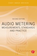
FIGURE 15.2 A crossfade between two 12 kHz sine waves, both generated to have the same level, and at a sampling frequency of 48 kHz, which provides four samples per period. On the left the tone generated has its first sample at 0 degrees (the dots), and hence the others at 90, 180, and 270 degrees of the sine wave period. On the right the first sample was made at 45 degrees and the following samples at 135, 225, and 315, respectively. The peak level of the first part is calculated by a digital meter to be 3 dB higher than that of the second part.
Test signals for the calibration of instrumentation can also be found on various CDs. However, if used for analog inputs or analog instruments, the analog output of the CD players must be checked. Using a computer-based editing program, it is possible to generate customized test tone sequences.
Test signals for digital instruments must be designed in a way that does not compromise the sampling rate. For instance, if the test frequency is exactly one fourth of the sampling rate there may be a problem.
PROCEDURE
The analog instrument is first calibrated with a constant tone at the alignment level (reference indication). Then the tone burst signal is applied, with the individual tone “packages” having the same level as the constant tone.
SVI or VU
According to IEC 60268-17 a Standard Volume Indicator or VU instrument must reach 99% (±10 %) of the reference indication (the “0” marking) for a tone length of 300 ms. If the tone length is shorter, then the reading must be lower. The fallback time should be identical to the reaction time, meaning the reading should fall to the bottom of the scale in 300 ms.
PPM (QPPM)
The reference indication of the IEC PPM (Quasi Peak Program Meter) instrument must be as follows according to IEC 60268-10:
Type I 1.55 V (+6 dB on Nordic scale
Type IIa 1.94 V (6 on the BBC scale)
Type IIb 2.18 V (+9 on the IIb scale)
When using the instruments to check line levels the accuracy of the scales must be checked as well by supplying other levels.
The dynamic response is defined by the reaction time. The Type I PPM must reach a level 2 dB below the reference indication for a tone length of 5 ms. In the pause of 1.5 seconds, the instrument must manage to fall 20 dB. The reading of the meter should be in accordance with the following scheme:
TABLE 15.1 Dynamic response for IEC PPM instruments in normal mode. However, for a tone burst with a duration of 5 ms, the display must reach 2 dB from the display that occurs at a constant tone.

LOUDNESS METER, EBU MODE
Calibrating the loudness meter is a little tricky, as there are several parameters to check. The meter will read both linear audio for the TP (True Peak) and k-weighted audio for the loudness reading resulting in LUFS (Loudness Unit with reference to full scale). The loudness reading includes gating for the integrated loudness. Additionally, there is the LRA (loudness range).
In the EBU mode these k-weighted readings are available: M (momentary loudness), S (short-term loudness) and I (integrated loudness).
Generally, the ITU prepares the test procedures for metering in broadcast. However, these procedures have not been finished yet. In the meantime the EBU has recommended the following series of test signals for alignment and calibration:
TABLE 15.2 Minimum requirements for test signals used with the EBU loudness meter.
