This chapter covers the following topics:
Multilayer Switching Overview
The Enterprise Composite Network Model for Building Cisco Multilayer Switched Networks
Introduction to the Cisco Catalyst Switches
Imagine a global network with multiple active data centers where one data center is able to handle all the functions of multiple data centers in the event of disaster. Consider that each data center network has a 100 percent uptime for normal operations that never interrupts user traffic, prevents worms and viruses, maintains stability and integrity during anomalous events, replicates data among different Data Centers, provides for immediate disaster recovery, routes inbound calls for employees through local Voice over IP (VoIP) networks, provides Virtual Private Network (VPN) access to remote-site users as if they were at the main site, migrates storage effortlessly, provides quality of service (QoS) adaptively, supports high-performance computing applications, and is self-maintaining, self-defending, self-upgrading, and self-repairing.
Although these types of data centers and campus networks might sound far-fetched, you can build these networks today by leveraging Cisco multilayer switched networks using the latest Cisco products and features. Convergence has many benefits, including reducing costs by consolidating procedures in network operation centers (NOC), consolidating platforms, reducing staff education curves, and so on. For example, consider training operation staff on multiple networks versus individual distinct networks.
This book focuses primarily on the Cisco Enterprise Campus Architecture of enterprise networks. However, a new focus in enterprise networks is developing—the data center. The data center has slightly different requirements than does the campus, but both use Cisco Catalyst switches and similar hierarchical designs. By definition in this book, the campus network includes the infrastructure for connecting the host devices, such as workstations. The campus network includes the server farm, but the server farm is now referred to as the data center. Unfortunately, as with network terms, the use of the terms campus network and data center is rather loose. This chapter intends to clarify each role.
By Cisco.com definition,
[the] Cisco Enterprise Campus Architecture empowers all enterprise users with advanced services, taking advantage of an intelligent, enterprise-wide network to increase revenue, productivity, and customer satisfaction while reducing the operational inefficiencies across the business.
The Enterprise Campus Architecture combines a core network infrastructure with an overlay of productivity-enhancing advanced technologies, including IP communications, mobility, and advanced security. This combination helps enterprises implement a resilient, highly available network that allows them to adapt more quickly to changing requirements, rapidly and securely enable new and emerging services, and streamline processes through optimized access to information and communications that increases employee effectiveness.
The server farm discussed in previous editions of this book has evolved into a more important component: the data center. By Cisco.com definition,
[the] Cisco Data Center Network Architecture provides a cohesive foundation for IT executives to better align data center resources with business priorities.
The Cisco Data Center Network Architecture allows IT organizations to achieve lower total cost of ownership (TCO), enhanced resilience, and greater agility by evolving data center infrastructures through consolidation, virtualization, and automation.
The data center encompasses many components including servers, server fabrics, applications, disk storage, storage-area networks (SAN), LANs, optical transports, and so on. As these technologies assemble into a single reference architecture, the phrases convergence and data center are becoming the new buzzwords.
In the previous edition, the motivation behind building multilayer switched networks was productivity. Although productivity is still a main reason for deploying Cisco converged switched networks, availability, security, and disaster-recovery techniques are the additional reasons. The new buzzword for building converged switched networks is virtualization.
In terms of productivity, Cisco multilayer switched networks are driving business productivity by building network architectures that are capable of boundless features, including voice, video, wireless data, and vast, reliable storage. These architectures embrace applications that support VoIP, wireless networking, remote access, and storage networking technologies. VoIP applications drive down the cost of ownership for telephony while effortlessly providing a multitude of telephony features to the end-user base on the intranet and on remote and wireless networks. Wireless technologies in the campus network are freeing individuals from their desks and increasing the productivity of mobile workers at the home and office for data and voice. Technologies such as VPNs are enabling telecommuters to be as productive as onsite workers. Therefore, the campus networks of yesterday are implementing design changes to quickly adopt these emerging applications to increase enterprise productivity. As a result, the traditional components of the Cisco multilayer switched networks are including specialized hardware for performance, high availability, and scalability to enable these applications. Multilayer switched networks are no longer networks of Layer 2 and Layer 3 switching, but rather are networks of Layer 2 through 7 switching with components for VoIP, wireless networking, storage networking, enhanced network management, and security.
In terms of availability, the requirements for these emerging applications such as voice, video, and data are 100 percent availability, high performance in terms of terabits per second (Tbps), and effortless scalability. Legacy data networks supported availability, performance, and scalability, but not to the degree needed by new applications for voice, video, and data. To provide for these applications and their needs, campus networks use a new design model, the Enterprise Composite Network Model, as a building block for enterprise networks. The model and its network components support features that are sophisticated, yet easily managed and sustained.
In terms of security, Cisco multilayer switched networks provide remote-site VPN solutions, firewall services, access control, and virus and worm mitigation and control. As companies continue to merge and add other companies, firewalls are no longer a requirement of just the Enterprise Edge. Firewalls are becoming more popular in local LANs where Catalyst switches support integrated firewall modules for the multigigabit speeds required for local LANs. Security features such as Secure Shell (SSH), 802.1x, access control lists (ACL), QoS, and private virtual LANs (VLAN) are necessary features that prevent unauthorized access. Companies cannot afford to allow free access to their private network and must account for every application and every user’s security in the entire network. With Cisco switches and routers, following security best practices and designs is easy and well integrated.
In terms of disaster recovery, Cisco multilayer switched networks are the networks for which newer storage solutions opt to transport data for replication and migration. The end goal of data replication is to provide instantaneous data recovery in the event of disaster or anomalous occurrence. As Network Area Storage (NAS) and Fibre Channel over IP (FCIP) solutions become more popular, the performance, features, and availability found with Cisco multilayer switched networks become even more crucial.
This book covers the building blocks of Cisco multilayer switched networks from mostly a Catalyst switch and Cisco IOS perspective. Both the hardware components, such as Cisco Express Forwarding (CEF)-based multilayer switching (MLS), and software features, such as the Hot Standby Routing Protocol (HSRP) and the Spanning Tree Protocol (STP), are covered in this text for an understanding of building Cisco multilayer switched networks in today’s highly demanding, highly available, secure, productive, and indestructible enterprise network environment.
This chapter provides a discussion of the basic elements of the Cisco multilayer switched network. The chapter begins with a synopsis of regulatory standards driving enterprise architectures, followed by a brief review of multilayer switching terminology, and then a discussion of the following elements of the network architecture:
Service Oriented Network Architecture (SONA)
The Enterprise Composite Network Model
The Cisco Catalyst Switches
The section on Cisco Catalyst switches is a brief introduction to the capabilities of each platform and the role it can play within modern campus networks. Chapter 2, “The Roles of Switches in Designing Cisco Multilayer Switched Networks,” provides a high-level overview of designing Cisco multilayer switched networks using these two elements: the Enterprise Composite Network Model and the Cisco Catalyst switches. Chapter 3, “Initial Configuration and Troubleshooting of Cisco Multilayer Switches,” introduces basic configuration of Catalyst switches using both Cisco IOS and Cisco CatOS. The remaining chapters focus specifically on implementing software and hardware features to support high performance, scalability, and availability in Cisco multilayer switched networks based on the network designs that are discussed in Chapter 2.
Many regulatory standards are driving enterprise architectures. Although most of these regulatory standards focus on data and information, they nonetheless drive network architectures. For example, to ensure that data is as safe as the Health Insurance Portability and Accountability Act (HIPAA) specifies, integrated security infrastructures are becoming paramount. Furthermore, the Sarbanes-Oxley Act, which specifies legal standards for maintaining the integrity of financial data, requires public companies to have multiple redundant data centers with synchronous copies of financial data.
Because the purpose of this book is to focus on enterprise architectures, you will not see detailed coverage of regulatory compliance. Nevertheless, these are important concepts for data centers, disaster recovery, and business continuance. You are encouraged to check out the following regulatory compliance standards:
Sarbanes-Oxley (http://www.sarbanes-oxley.com)
HIPAA (http://www.hippa.com)
SEC 17a-4, “Records to Be Preserved by Certain Exchange Members, Brokers and Dealers” (http://www.sec.gov/rules/interp/34-47806.htm)
The next section on hardware- and software-switching terminology begins the technical discussion of building Cisco converged switched networks.
This book refers to the terms hardware-switching and software-switching regularly throughout the text. The industry term hardware-switching refers to the act of processing packets at any layer, 2 through 7, via specialized hardware components referred to as application-specific integrated circuits (ASIC). ASICs, application-specific integrated circuits, are generally able to reach throughput at wire speed without performance degradation for advanced features such as QoS marking, ACL processing, or IP rewriting.
Note
Other terms used to describe hardware-switching are in hardware, using ASICs, and hardware-based. These terms are used interchangeably throughout the text. MLS (multilayer switching) is another term commonly used to describe hardware-switching. The term MLS can be confusing; for example, with the Catalyst 5500, the term MLS described a legacy hardware-switching method and feature. With today’s terminology, MLS describes the capability to route and switch frames at line-rate (the speed of all ports sending traffic at the same time, full-duplex, at the maximum speed of the interface) with advanced features such as Network Address Translation (NAT), QoS, access-controls, and so on using ASICs. Chapter 9, “Understanding and Configuring Multilayer Switching,” discusses the MLS terminology in more detail. For the next several chapters, MLS and hardware-switching simply represent switching and routing packets and frames in hardware at high speeds.
Switching and routing traffic via hardware-switching is considerably faster than the traditional software-switching of frames via a CPU. Many ASICs, especially ASICs for Layer 3 routing, use specialized memory referred to as ternary content addressable memory (TCAM) along with packet-matching algorithms to achieve high performance, whereas CPUs simply use higher processing rates to achieve greater degrees of performance. Generally, ASICs are able to achieve higher performance and availability than CPUs. In addition, ASICs scale easily in switching architecture, whereas CPUs do not. ASICs integrate not only on Supervisor Engines but also on individual line modules of Catalyst switches to hardware-switch packets in a distributed manner.
ASICs do have memory limitations. For example, the Catalyst 6500 family of switches is able to accommodate ACLs with a larger number of entries compared to the Catalyst 3500 family of switches due to the larger ASIC memory on the Catalyst 6500 family of switches. Generally, the size of the ASIC memory is relative to the cost and application of the switch. Furthermore, ASICs do not support all the features of the traditional Cisco IOS. For instance, the Catalyst 6500 family of switches with a Supervisor Engine 720 and an MSFC3 (Multilayer Switch Feature Card) must software-switch all packets requiring NAT without the use of specialized line modules. As products continue to evolve and memory becomes cheaper, ASICs gain additional memory and feature support.
Traditionally, switches provided only Layer 2 functionality based on the MAC address. Current-generation switches, however, are capable of not only Layer 3 IP routing but also advanced features such as Layer 7 network access control (NAC), content-intelligence, load balancing, high availability, power distribution for IP phones, and a multitude of other features. In most campus networks, Layer 3 switches are replacing traditional routers. Furthermore, Layer 3 switches are migrating to the commercial and Internet service provider (ISP) markets because they are versatile and have high port density. This section of the chapter highlights the fundamentals of Layer 2 and Layer 3 switching. Later sections of this book discuss the Enterprise Composite Network Model for building multilayer switched networks and introduce the Cisco Catalyst switches.
Product marketing in the networking technology field uses many terms to describe product capabilities. In many situations, product marketing stretches the use of technology terms to distinguish products among multiple vendors. One such case is the terminology of Layers 2, 3, 4, and 7 switching. These terms are generally exaggerated in the networking technology field and need careful review.
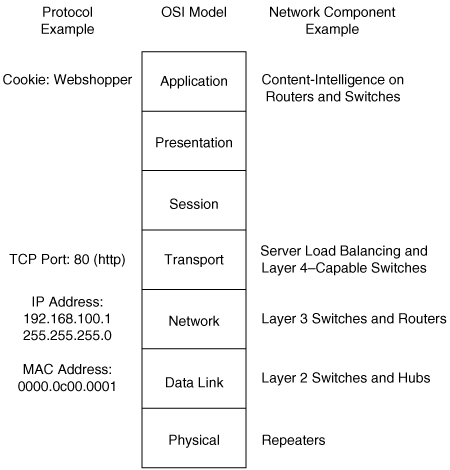
The Layer 2, 3, 4, and 7 switching terminology correlates switching features to the OSI reference model. Figure 1-1 illustrates the OSI reference model and its relationship to protocols and network hardware.
Layer 2 switching strictly focuses on the data link layer, which means that Layer 2 switches are capable of switching packets only based on MAC addresses. Layer 2 switches increase network bandwidth and port density without much complexity. The term Layer 2 switching implies that frames forwarded by the switch are not modified in any way; however, Layer 2 switches such as the Catalyst 2960 are capable of QoS marking and network access control at Layer 4, whereas QoS does indeed modify the frame, and QoS and network access control do not affect the performance of the switch. An example of QoS marking at Layer 4 is marking the differentiated services code point (DSCP) bits in the IP header based on the TCP port number in the TCP header.
Legacy Layer 2 switches are limited in network scalability due to many factors. Consequently, all network devices on a legacy Layer 2 switch must reside on the same subnet and, as a result, exchange broadcast packets for address resolution purposes. Network devices that are grouped together to exchange broadcast packets constitute a broadcast domain. Layer 2 switches flood unknown unicast, multicast, and broadcast traffic throughout the entire broadcast domain. As a result, all network devices in the broadcast domain process all flooded traffic. As the size of the broadcast domain grows, its network devices become overwhelmed by the task of processing this unnecessary traffic. This caveat prevents network topologies from growing to more than a few legacy Layer 2 switches. Lack of QoS and security features further prevents the use of Layer 2 switches in campus networks and data centers.
However, all current and most legacy Cisco Catalyst switches support VLANs, which segment traffic into separate broadcast domains and, as a result, IP subnets. VLANs overcome several of the limitations of the basic Layer 2 networks, as discussed in the previous paragraph. This book discusses VLANs in Chapter 4, “Implementing and Configuring VLANs.”
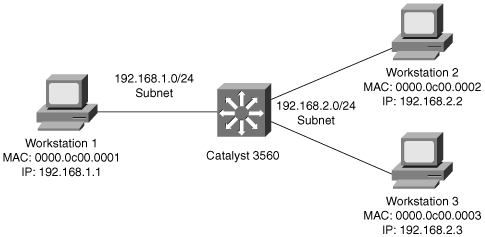
Figure 1-2 illustrates an example of a Layer 2 switch with workstations attached. Because the switch is only capable of MAC address forwarding, the workstations must reside on the same subnet to communicate. The “Layer 2 Switching in Depth” section discusses Layer 2 switching in more detail.
Layer 3 switches include Layer 3 routing capabilities. Many of the current-generation Catalyst Layer 3 switches are able to use routing protocols such as BGP, RIP, OSPF, and EIGRP to make optimal forwarding decisions. Catalyst Layer 3 switches are also capable of PIM multicasting and redundancy using the HSRP or the Virtual Router Redundancy Protocol (VRRP). These Layer 3 features are discussed in later chapters. Figure 1-3 illustrates a Layer 3 switch with several workstations attached. In this example, the Layer 3 switch routes packets between the two subnets.
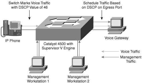
Layer 4 and 7 switching terminology is not as straightforward as Layers 2 and 3 switching terminology. Layer 4 switching implies switching based on protocol sessions. In other words, Layer 4 switching uses not only source and destination IP addresses in switching decisions, but also IP session information contained in the TCP and User Datagram Protocol (UDP) portions of the packet. The most common method of distinguishing traffic with Layer 4 switching is to use the TCP and UDP port numbers. Server load balancing, a Layer 4 to Layer 7 switching feature, can use TCP information such as TCP SYN, FIN, and RST to make forwarding decisions. (Refer to RFC 793 for explanations of TCP SYN, FIN, and RST.) As a result, Layer 4 switches are able to distinguish different types of IP traffic flows, such as differentiating the FTP, Network Time Protocol (NTP), HTTP, Secure HTTP (S-HTTP), and Secure Shell (SSH) traffic. Layer 4 switches generally use this differentiation for traffic filtering, QoS, and load balancing versus basic IP packet routing. All Cisco Layer 3 switches, such as the Catalyst 3560, 3750, 4500 (with Supervisor Engines II plus, III, IV, and V), 4900, and 6500 families of switches are capable of Layer 4 switching features, including load balancing, traffic filtering, and QoS based on IP TCP and UDP port numbering. Figure 1-4 illustrates a Layer 3 switch that is capable of Layer 4 QoS. In this example, the Layer 3 switch marks packets destined for a voice gateway with a DSCP value of 46 to differentiate service versus the management traffic from the management workstations.
To achieve a high level of performance, Layer 4 switching requires hardware-forwarding capabilities with large memory capabilities. Later chapters of this book discuss the hardware-forwarding capabilities of several Catalyst platforms and their limitations.
Layer 7 switches operate at the application layer of the OSI reference model. Layer 7 switching capability implies content-intelligence. Content-intelligence with respect to web browsing implies features such as inspection of URLs, cookies, host headers, and so on. Content-intelligence with respect to VoIP may include distinguishing call destinations such as local or long distance for purposes of QoS. Content-intelligence is a powerful feature; however, switches use content-intelligence primarily for QoS and security rather than basic packet forwarding. At the time of publication, Cisco Catalyst Layer 3 switches are capable of Layer 7 switching on specific Catalyst switch models through the use of specialized hardware, software, or line modules.
Table 1-1 summarizes the layers of the OSI model with their respective protocol data units (PDU), which represent the data exchanged at each layer. The table also contains a column illustrating sample device types that are operating at the specified layer.
Table 1-1. PDU and Sample Device Relationship to the OSI Model
OSI Layer | PDU Type | Device Example | Address | |
|---|---|---|---|---|
1 | Physical | Electrical signals | Repeater, transceiver | None |
2 | Data link | Frames | Switches | MAC address |
3 | Network | Packet | Router, multilayer switches | IP address |
4 | Transport | TCP or UDP data segments | Multilayer switch load balancing based on TCP port number | TCP or UDP port numbering |
7 | Application | Embedded application information in data payload | Multilayer switch using Network-Based Application Recognition (NBAR) to permit or deny traffic | Embedded information in data payload |
Layer 2 switching is hardware-based bridging. In a Layer 2 switch, ASICs handle frame forwarding. Moreover, Layer 2 switches deliver the ability to increase bandwidth to the wiring closet without adding unnecessary complexity to the network. At Layer 2, no modification is required to the frame content when going between Layer 1 interfaces, such as Fast Ethernet to 10 Gigabit Ethernet.
In brief, the network design properties of current-generation Layer 2 switches include the following:
Is designed for near wire-speed performance
Is built using high-speed, specialized ASICs
Has low latency
Is scalable to several switches
Supports Layer 3 functionality such as Internet Group Management Protocol (IGMP) snooping and QoS marking
Offers limited scalability in large networks without Layer 3 boundaries
Note
Some Layer 2 switches are able to do packet rewriting for QoS marking. One such example is the Cisco Catalyst 2960’s ability to mark ingress frames with a Layer 2 class of service (CoS) value or a Layer 3 DSCP value. This book explains QoS in more detail in later chapters.
At the time of publication, the only shipping Cisco Catalyst switches that fit into the pure Layer 2 switch category are the Catalyst 2940, 2950, 2955, 2960, 2970, and 4500 with Supervisor II+ families of switches. All other currently shipping switches are capable of Layer 3 routing.
Layer 3 switching is hardware-based routing. Layer 3 switches overcome the inadequacies of Layer 2 scalability by providing routing domains. The packet forwarding in Layer 3 switches is handled by ASICs and other specialized circuitry. A Layer 3 switch performs everything on a packet that a traditional router does, including the following:
Determines the forwarding path based on Layer 3 information
Validates the integrity of the Layer 3 packet via the Layer 3 checksum
Verifies and decrements packet TTL (Time-to-Live) expiration
Rewrites the source and destination MAC address during IP rewrites
Updates Layer 2 CRC during Layer 3 rewrite
Processes and responds to any option information in the packet such as the Internet Connectivity Management Protocol (ICMP) record
Updates forwarding statistics in the Management Information Base (MIB)
Applies security controls and QoS if required
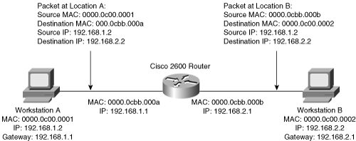
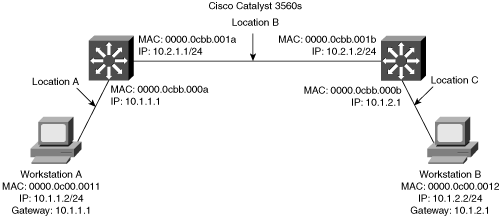
Layer 3 routing requires the ability of packet rewriting. Packet rewriting occurs on any routed boundary. Figure 1-5 illustrates the basic packet rewriting requirements of Layer 3 routing in an example in which two workstations are communicating using ICMP.
Address Resolution Protocol (ARP) plays an important role in Layer 3 packet rewriting. When Workstation A in Figure 1-5 sends five ICMP echo requests to Workstation B, the following events occur (assuming all the devices in this example have yet to communicate):
Workstation A sends an ARP request for its default gateway. Workstation A sends this ARP to obtain the MAC address of the default gateway. Without knowing the MAC address of the default gateway, Workstation A is unable to send any traffic outside of the local subnet. Note, in this example, that Workstation A’s default gateway is the Cisco 2600 router with two Ethernet interfaces.
The default gateway, the Cisco 2600, responds to the ARP request with an ARP reply, sent to the unicast MAC address and IP address of Workstation A, indicating the default gateway’s MAC address. The default gateway also adds an ARP entry for Workstation A in its ARP table upon receiving the ARP request.
Workstation A sends the first ICMP echo request to the destination IP address of Workstation B with a destination MAC address of the default gateway.
The router receives the ICMP echo request and determines the shortest path to the destination IP address.
Because the default gateway does not have an ARP entry for the destination IP address, Workstation B, the default gateway drops the first ICMP echo request from Workstation A. The default gateway drops packets in the absence of ARP entries to avoid storing packets that are destined for devices without ARP entries as defined by the original RFCs governing ARP.
The default gateway sends an ARP request to Workstation B to get Workstation B’s MAC address.
Upon receiving the ARP request, Workstation B sends an ARP response with its MAC address.
By this time, Workstation A is sending a second ICMP echo request to the destination IP of Workstation B via its default gateway.
Upon receipt of the second ICMP echo request, the default gateway now has an ARP entry for Workstation B. The default gateway in turn rewrites the source MAC address to itself and the destination MAC to Workstation B’s MAC address, and then forwards the frame to Workstation B.
Workstation B receives the ICMP echo request and sends an ICMP echo reply to the IP address of Workstation A with the destination MAC address of the default gateway.
Figure 1-5 illustrates the Layer 2 and Layer 3 rewriting at different places along the path between Workstation A and B. This figure and example illustrate the fundamental operation of Layer 3 routing and switching.
The primary difference between the packet-forwarding operation of a router and Layer 3 switching is the physical implementation. Layer 3 switches use different hardware components and have greater port density than traditional routers.
These concepts of Layer 2 switching, Layer 3 forwarding, and Layer 3 switching are applied in a single platform: the multilayer switch. Because it is designed to handle high-performance LAN traffic, a Layer 3 switch is locatable when there is a need for a router and a switch within the network, cost effectively replacing the traditional router.
Multilayer switching combines Layer 2 switching and Layer 3 routing functionality. Generally, the networking field uses the terms Layer 3 switch and multilayer switch interchangeably to describe a switch that is capable of Layer 2 and Layer 3 switching. In specific terms, multilayer switches move campus traffic at wire speed while satisfying Layer 3 connectivity requirements. This combination not only solves throughput problems but also helps to remove the conditions under which Layer 3 bottlenecks form. Moreover, multilayer switches support many other Layer 2 and Layer 3 features besides routing and switching. For example, many multilayer switches support QoS marking at Layer 2 using the CoS field and QoS marking at Layer 3 using DSCP. Combining both Layer 2 and Layer 3 functionality and features allows for ease of deployment and simplified network topologies.
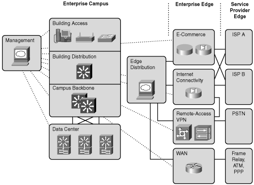
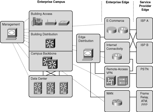
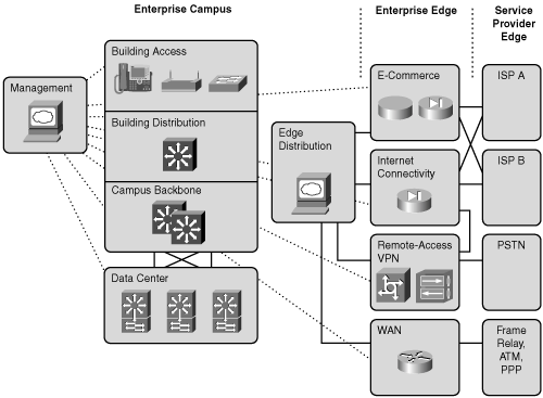
Now that you have an understanding of some basic switching concepts, this section provides a high-level overview of building Cisco multilayer switched networks by describing the Enterprise Composite Network Model, a hierarchy of functional areas, each with its own components. Figure 1-6 shows the Enterprise Composite Network Model at a high-level view. This section discusses each functional area and component in Figure 1-6. Furthermore, this section begins with an explanation of the Cisco Architecture for Voice, Video and Integrated Data (AVVID) framework upon which the campus design architecture is built.
Specifically, this section covers the following topics:
The Cisco Service-Oriented Network Architecture (SONA)
The Cisco Intelligent Information Network (IIN)
The Cisco AVVID framework
The purpose of layer 3 networks
The enterprise models
The Enterprise Composite Network Model hierarchy
The Enterprise Campus functional area
The Enterprise Edge functional area
The Service Provider Edge functional area
The Cisco Enterprise Data Center
So far, the primary focus in this chapter has been on building a campus network for moving bits of data, voice, and video. As we all know, building campus networks is more than just moving bits. Many enterprises find themselves unlinked between network components and information assets. Furthermore, many enterprises have hundreds of “siloed” applications and databases that cannot communicate with each other. These disparate applications and databases are usually a result of specific requirements, delivery timelines, and distinct enterprise organizational structures. For example, information cannot be accessed easily by sales, customer service, or purchasing groups without creating different overlaying networks that join applications and information. Many enterprises have found that this unplanned expansion has left them with multiple systems and distributed resources that are uncoordinated and underused. These disparate systems are also difficult and costly to manage.
Consider your enterprise network. How many different database systems does your enterprise use? Do human resources, staff, shipping, sales, support, and marketing all use the same database or applications? How many diverse networks does your enterprise contain? Does your network have SAN islands or InfiniBand clusters?
The campus network still remains as the platform that can connect and enable all components of IT infrastructure transparently. Using Cisco SONA, enterprises can optimize applications, processes, and resources to deliver greater business benefits. By making the network more capable and intelligent, enterprises can improve the efficiency of everything the network touches while freeing funds for new strategic investments and innovation. Standardization increases asset efficiency by lowering operational costs to support the same number of assets. Virtualization optimizes use of assets such that extra physical resources can be logically segmented to be used across distributed departments. The widespread effect of the newly gained efficiencies across the network offers increased flexibility and scalability, thus creating a significant impact on growth, customer loyalty, and profitability—thereby improving the overall ability to compete.
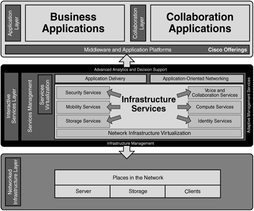
The Cisco SONA framework outlines how enterprises can evolve to an Intelligent Information Network that accelerates applications, business processes, and resources and enables IT to have a greater impact on business. Cisco SONA leverages Cisco and Cisco partner solutions, services, and experience working with enterprises across industries to deliver proven, scalable business solutions. The Cisco SONA framework illustrates how to build integrated systems across a fully converged, intelligent network that significantly improves flexibility and increases efficiency. Enterprises can implement this comprehensive intelligence into the entire network, including the data center, branch offices, and campus environments. Figure 1-7 illustrates Cisco SONA.
SONA is divided into the following three layers:
Network infrastructure layer—. The interconnected and converged network foundation
Interactive services layer—. The services structure that delivers efficient allocation of resources to applications and business processes
Application layer—. The business and collaborative applications that take advantage of the efficiencies of the interactive services and the network infrastructure
The network infrastructure layer is essentially the network itself. In terms of building converged switched networks, the network infrastructure includes the campus network and the data center. However, the network infrastructure layer includes all other networking components such as optical transports, firewalls, load-balancers, security appliances, and so on.
The interactive services layer includes the tools and network appliances that provide intelligent services and virtualization. For example, the VMWare product allows multiple operating systems to run on a single server and reuse wasted resources for applications. VMWare is an intelligent service. In terms of Cisco products, VFrame is an intelligent service because it has the capability to virtualize a cluster of servers to perform tasks as a single entity rather than as separate services. VFrame reduces cost and effectively uses resources in the network.
The application layer is the application itself that uses both the intelligent services and network infrastructure. Examples include SAP, Oracle, .NET, Microsoft Exchange, and so on.
In relation to building converged switched networks, this book focuses primarily on the network infrastructure layer. For more information on SONA, search for SONA on Cisco.com.
The IIN is a Cisco Systems 3- to 5-year vision for growing business value through increasing investment in the network.
The Cisco vision of the future IIN encompasses these features:
Integration of networked resources and information assets that have been largely unlinked—. The modern converged networks with integrated voice, video, and data require that IT departments more closely link the IT infrastructure with the network.
Intelligence across multiple products and infrastructure layers—. The intelligence built into each component of the network is extended network-wide and applies end to end.
Active participation of the network in the delivery of services and applications—. With added intelligence, the IIN makes it possible for the network to actively manage, monitor, and optimize service and application delivery across the entire IT environment.
With the listed features, the IIN offers much more than basic connectivity, bandwidth for users, and access to applications. The IIN offers end-to-end functionality and centralized, unified control that promotes true business transparency and agility.
The IIN technology vision offers an evolutionary approach that consists of three phases in which functionality can be added to the infrastructure as required:
Integrated transport—. Everything—data, voice, and video—consolidates onto an IP network for secure network convergence. By integrating data, voice, and video transport into a single, standards-based, modular network, organizations can simplify network management and generate enterprise-wide efficiencies. Network convergence also lays the foundation for a new class of IP-enabled applications delivered through Cisco IP Communications solutions.
Integrated services—. After the network infrastructure has been converged, IT resources can be pooled and shared or “virtualized” to flexibly address the changing needs of the organization. Integrated services help to unify common elements, such as storage and data center server capacity. By extending virtualization capabilities to encompass server, storage, and network elements, an organization can transparently use all its resources more efficiently. Business continuity is also enhanced because shared resources across the IIN provide services in the event of a local system failure.
Integrated applications—. With Application-Oriented Networking (AON) technology, Cisco has entered the third phase of building the IIN. This phase focuses on making the network “application-aware” so that it can optimize application performance and more efficiently deliver networked applications to users. In addition to capabilities such as content caching, load balancing, and application-level security, Cisco AON makes it possible for the network to simplify the application infrastructure by integrating intelligent application message handling, optimization, and security into the existing network.
The Cisco IIN vision and Cisco SONA yield today’s Enterprise Composite Network Model. Before discussing the Enterprise Composite Network Model, the section that follows provides a quick review of the Cisco AVVID framework.
The Cisco AVVID framework still exists, yet it has given way to Cisco SONA. Nevertheless, many enterprise design reference architectures still use the Cisco AVVID framework.
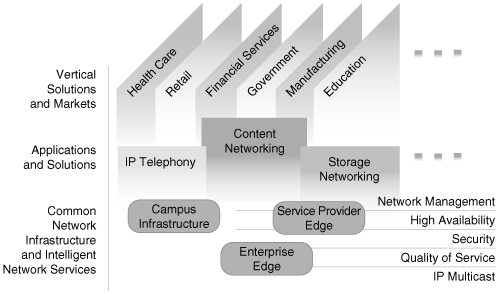
Cisco AVVID is an enterprise-wide, standards-based network architecture that provides a road map for combining business and technology strategies into a cohesive model. Figure 1-8 illustrates this model.
The goal of any network architecture is to provide a road map and a guide for ongoing network planning, design, and implementation. In addition, network architectures provide a coherent framework that unifies disparate solutions onto a single foundation.
To satisfy the network architecture goal, the Cisco AVVID framework establishes several components. The primary components include network infrastructure, intelligent network services, and network solutions. These components build solutions and applications such as storage, Internet service, and IP telephony.
In summary, the Cisco AVVID framework supports the following key components:
Network infrastructure
Intelligent network services
Network solutions
The network infrastructure component includes the hardware and software used to send, receive, and manage packets that are transmitted between network devices throughout the enterprise. The network infrastructure includes the transmission media and devices that control transmission paths, such as private and public transport media. Examples of these devices include routers, LAN switches, WAN switches, call gateways, and private branch exchanges (PBX).
The intelligent network services allow end users to operate in a controlled, secure environment in which the network provides differentiated services. Intelligent network services essentially add intelligence to the network infrastructure beyond just moving a datagram between two network devices. Intelligent network services allow for application awareness and content-intelligence. Intelligent network services also include functions such as security, network management, quality of service, IP multicast, and high availability.
The network solutions include the hardware and software that use the network infrastructure and intelligent network services to their advantage. Network solutions allow enterprises to make business decisions about the business itself as well as about networks and the technologies and applications that run on them. Network-based applications enable an enterprise organization to interact more effectively with customers, suppliers, partners, and employees. Customer service, commerce, supplier, and other intranet applications run over the network infrastructure enabled by intelligent network services. The end result of these applications is increased profitability and productivity. Examples of network solutions that run over network infrastructures using the Cisco AVVID framework are IP telephony, multi-unit applications, content networking, and storage networking.
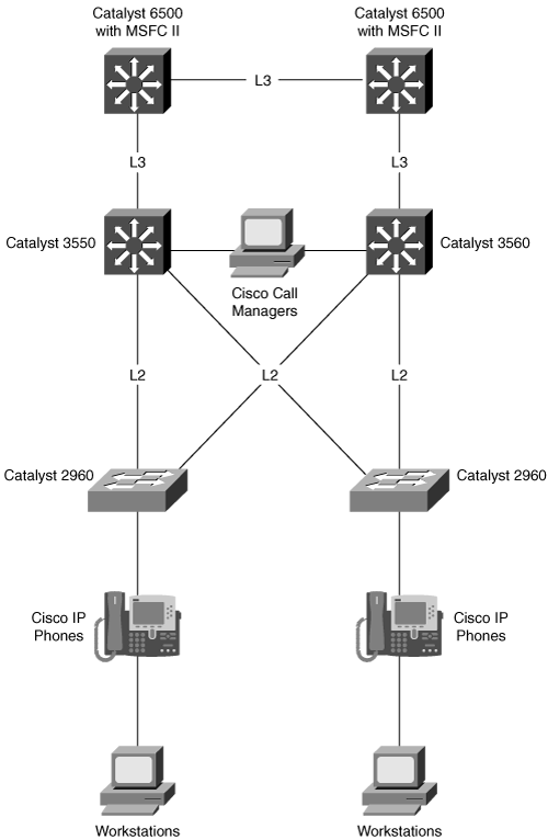
An example of an application that benefits from using the Cisco AVVID framework is IP telephony. Figure 1-9 illustrates a basic network topology using the Cisco AVVID framework. In this example, IP telephony itself is the network solution. The multilayer switches provide the network infrastructure, whereas QoS features of the multilayer switch provide the intelligent network service. In this specific example, the multilayer switches prioritize all IP telephony voice and signaling traffic over standard data traffic to ensure voice quality.
The motivation behind building Layer 3 networks in the LAN is simple and straightforward—Layer 3 networks add security, availability, performance, and features that are not available with Layer 2 networks. This book could discuss in detail how Layer 2 networks send broadcast frames to every port, broadcast unknown unicast packets to every port, and so on. However, the reasons for using Layer 3 networks today are security, availability, performance, and the ability to configure advanced features.
Security in Layer 3 networks is done via ACLs. Attempting to use Layer 2-based ACLs would be an impossible task in large networks. Access control via IP address or application (Layer 4 port number or Layer 7 application awareness) is far simpler than trying to apply access control by using MAC addresses that are unique for each host. Just imagine trying to apply security by using MAC address-based access control lists with over 1000 hosts, or even 10,000 hosts? Furthermore, Layer 3 redundancy is much faster, more stable, more consistent, and easier to configure than Layer 2 redundancy. For example, Layer 3 routing protocols converge significantly faster than the traditional STP. In addition, routing protocols are session-based, whereas STP is not.
Features are another important aspect of Layer 3 networks; server load balancing, NAT, and NetFlow (static analysis of IP flows) are not available at Layer 2. The list of reasons for deploying Layer 3 networks could go on almost indefinitely; however, most of the reasons are legacy now, and Layer 3 networks are the focus of any network designs today. The next section introduces the Enterprise Composite Network Model for building Cisco multilayer switched networks.
A common situation in which Layer 3 networks might not be the best choice is in data centers where a service module is needed in the distribution layer. In this case, due to bandwidth restrictions on the service module, Layer 2 topologies can be extended up to the distribution layer.
Cisco provides the enterprise-wide systems architecture that helps companies to protect, optimize, and grow the infrastructure that supports business processes. The architecture provides integration of the entire network—campus, data center, WAN, branches, and teleworkers—offering staff secure access to the tools, processes, and services.
Cisco Enterprise Campus Architecture—. Combines a core infrastructure of intelligent switching and routing with tightly integrated productivity-enhancing technologies, including IP Communications, mobility, and advanced security. The architecture provides the enterprise with high availability through a resilient multilayer design, redundant hardware and software features, and automatic procedures for reconfiguring network paths when failures occur. Multicast provides optimized bandwidth consumption, and QoS prevents oversubscription to ensure that real-time traffic, such as voice and video, or critical data is not dropped or delayed. Integrated security protects against and mitigates the impact of worms, viruses, and other attacks on the network, even at the port level. Cisco enterprise-wide architecture extends support for standards, such as 802.1x and Extensible Authentication Protocol (EAP). The Cisco enterprise-wide architecture also provides the flexibility to add IP Security (IPsec) and Multiprotocol Label Switching VPNs (MPLS VPN), identity and access management, and VLANs to compartmentalize access. This helps improve performance and security and decreases costs.
Cisco Enterprise Data Center Architecture—. A cohesive, adaptive network architecture that supports the requirements for consolidation, business continuance, and security while enabling emerging service-oriented architectures, virtualization, and on-demand computing. IT staff can easily provide departmental staff, suppliers, or customers with secure access to applications and resources. This approach simplifies and streamlines management, significantly reducing overhead. Redundant data centers provide backup using synchronous and asynchronous data and application replication. The network and devices offer server and application load balancing to maximize performance. This solution allows enterprises to scale without major changes to the infrastructure.
Cisco Enterprise Branch Architecture—. Allows enterprises to extend head-office applications and services, such as security, IP Communications, and advanced application performance, to thousands of remote locations and users, or to a small group of branches. Cisco integrates security, switching, network analysis, caching, and converged voice and video services into a series of integrated services routers in the branch so that enterprises can deploy new services when they are ready without buying new equipment. This solution provides secure access to voice, mission-critical data, and video applications anywhere, anytime. Advanced network routing, VPNs, redundant WAN links, application content caching, and local IP telephony call processing provide a robust architecture with high levels of resilience for all the branch offices. An optimized network leverages the WAN and LAN to reduce traffic and save bandwidth and operational expenses. Enterprises can easily support branch offices with the ability to centrally configure, monitor, and manage devices located at remote sites, including tools, such as AutoQoS, that proactively resolve congestion and bandwidth issues before they affect network performance.
Cisco Enterprise Teleworker Architecture—. Allows enterprises to securely deliver voice and data services to remote small or home offices over a standard broadband access service, providing a business-resiliency solution for the enterprise and a flexible work environment for employees. Centralized management minimizes IT support costs, and robust integrated security mitigates the unique security challenges of this environment. Integrated security and identity-based networking services enable the enterprise to help extend campus security policies to the teleworker. Staff can securely log into the network over an “always-on” VPN and gain access to authorized applications and services from a single cost-effective platform. The productivity can further be enhanced by adding an IP phone, providing cost-effective access to a centralized IP Communications system with voice and unified messaging services.
Cisco Enterprise WAN Architecture—. Offers the convergence of voice, video, and data services over a single IP Communications network. This approach enables enterprises to cost-effectively span large geographic areas. QoS, granular service levels, and comprehensive encryption options help ensure the secure delivery of high-quality corporate voice, video, and data resources to all corporate sites, enabling staff to work productively and efficiently from any location. Security is provided with multiservice VPNs (IPsec and MPLS) over Layer 2 or Layer 3 WANs, hub-and-spoke, or full-mesh topologies.
This book focuses primarily on the Cisco Enterprise Campus Architecture, which uses the Enterprise Composite Network Model to divide and modularize the architecture into multiple functional areas. This division and modularity allows for flexibility in network design and facilitates ease of implementation and troubleshooting. The next section goes into detail regarding the Enterprise Composite Network Model.
The Enterprise Composite Network Model provides a modular framework for designing networks. The modularity within this model allows for flexibility in network design and facilitates implementation and troubleshooting. This section describes the Enterprise Composite Network Model and, at a high-level overview, how the model addresses enterprise network requirements for performance, scalability, and availability.
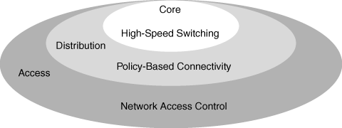
Nearly a decade ago, Cisco introduced a hierarchical design model as a tool for network designers to approach network design from the physical, logical, and functional viewpoints. The hierarchical model divides networks into the access, distribution, and core layers. Figure 1-10 illustrates the network design hierarchical model.
The access layer provides user access to network devices. In a network campus, the access layer generally incorporates Layer 2 switches that interconnect LAN devices such as workstations and servers. In the WAN environment, the access layer provides sites with access to the corporate network using a WAN technology such as broadband or Frame Relay.
The distribution layer aggregates the wiring closets and uses Layer 2 and Layer 3 switching to segment workgroups, implement security policies, restrict bandwidth, and isolate network problems. These measures prevent anomalous events in the distribution and access layers from affecting the core layer. Furthermore, routing and packet manipulation such as NAT and QoS marking commonly occur in the distribution layer. Redundancy in this scenario is carried out by HSRP or the Gateway Load Balancing Protocol (GLBP) and the use of routing protocols. Later chapters discuss these features in more detail.
The core layer describes a high-speed backbone, in which packets are switched as fast as possible. Because the core is critical for connectivity, it provides for high availability and adapts quickly to routing and topology changes.
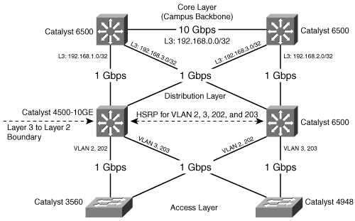
Figure 1-11 illustrates a sample network topology that uses the hierarchical model. This sample network topology scales the distribution and access layers to two switches for simplicity. In an applied network topology, the distribution and access layers comprise numerous switches.
The hierarchical model was useful for designing basic enterprise networks. However, enterprise networks that employ multiple applications and services need additional modularity because the hierarchical model is difficult to scale logically. This need for additional modularity, or building blocks, led to the development of the Enterprise Composite Network Model.
The Enterprise Composite Network Model introduces additional modularity into the network structure. The entire network is divided into functional areas that represent several distinct regions of the network. The functional areas of the Enterprise Composite Network Model still use the hierarchical model as the basic building block.
The Enterprise Composite Network Model includes the following four major functional areas:
Enterprise Campus
Enterprise Edge
Service Provider Edge
Data Center
The Enterprise Campus contains the modules that are required to build a hierarchical, highly robust campus network that offers performance, scalability, and high availability. This functional area contains the network elements that are required for independent operation within a single campus. This functional area does not offer remote connections or Internet access.
Note
In the context of this chapter, a campus is defined as one or more buildings, with multiple virtual and physical networks, connected across a high-performance, multilevel switched backbone.
The Enterprise Edge aggregates connectivity from the various elements at the edge of the enterprise network. The Enterprise Edge functional area filters traffic from the Edge modules and routes it into the Enterprise Campus functional area. The Enterprise Edge functional area contains all the network elements for efficient and secure communication between the Enterprise Campus and remote locations, remote users, home users, and the Internet.
The Service Provider Edge provides connectivity to services that are implemented by service providers. The Service Provider Edge functional area enables communications with other networks using different WAN technologies and ISPs.
The Data Center provides connectivity to server frames and services and consolidates the data processing and storage-related functions of the enterprise network.
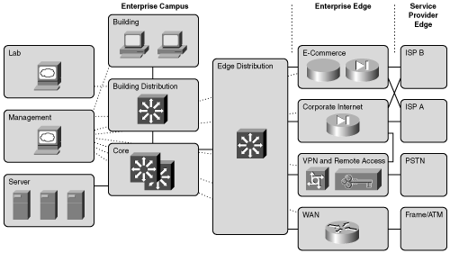
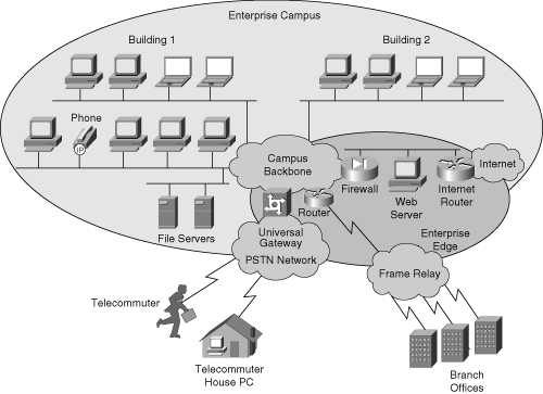
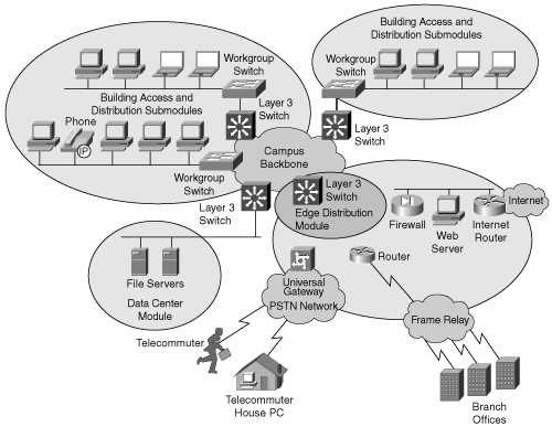
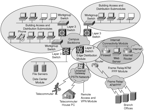
Figures 1-12 and 1-13 illustrate, respectively, the Enterprise Composite Network Model and a sample implementation of the Enterprise Composite Network Model.
Figure 1-13 shows an enterprise network with the major components of the Enterprise Composite Network Model. The network is divided into the Enterprise Campus and Enterprise Edge functional areas, connected by the Campus Backbone submodule.
The functional areas of the Enterprise Composite Network Model orchestrate the following criteria for designing multilayer switched networks:
Define a deterministic network with clearly defined boundaries between modules. The model has clear demarcation points such that the designer knows exact traffic patterns.
Increase network scalability and ease the design task by making each module discrete.
Provide scalability by allowing enterprises to add modules easily. As network complexity grows, designers are able to add new functional modules without disrupting other modules.
Offer more network integrity in network design, allowing the designer to add services and solutions without changing the underlying network infrastructure or network design.
In brief, the Enterprise Composite Network Model divides the network into physical, logical, and functional areas. These functional areas establish their own hierarchical model of Building Access, Building Distribution, and Campus Backbone submodules. Usually, the Campus Backbone connects multiple functional areas that extend into each functional area as a set of interfaces.
The Enterprise Campus defines a functional area of the Enterprise Composite Network Model, as described in the previous section. The Enterprise Campus functional area includes the following Enterprise Composite modules:
Campus Infrastructure
Network Management
Edge Distribution
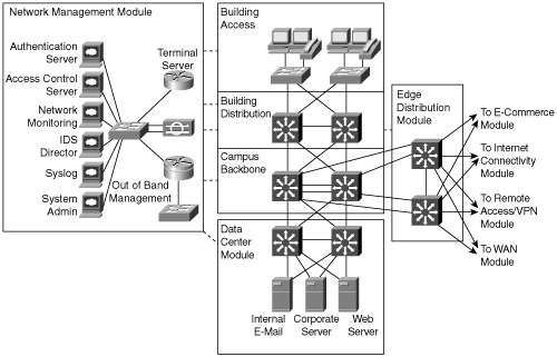
Each module has a specific function within the campus network. This section describes the modules that comprise an Enterprise Campus network and explains how the infrastructure meets the need for performance, scalability, and availability. Figure 1-14 illustrates the Enterprise Campus functional area.
The Campus Infrastructure module connects the other Enterprise Campus modules. This module connects multiple physical areas in a Campus Backbone submodule. The physical areas may be floors of a building, lab areas, buildings, or any other physical boundary. These physical areas connect to the Campus Backbone submodule through Building Access and Distribution submodules.
Generally, the Building Access and Building Distribution submodules are referred to as such because buildings are the usual boundaries. However, the access and distribution submodules may apply to any single physical or logical boundary, such as an intermediate distribution frame (IDF), floor, department, or area. The remainder of this text uses the terms Building Access submodule and access layer submodule interchangeably and uses the terms Building Distribution submodule and distribution layer submodule interchangeably as well.
The Building Access submodule, also known as the access layer submodule, contains end-user workstations, IP phones, and the Layer 2 access switches that connect devices to the Building Distribution submodule. The Building Access submodule provides for network access and performs important services such as Layer 2 and Layer 3 broadcast and multicast suppression; access control, such as 802.1x, packet filtering, and protocol filtering; and QoS.
The Building Distribution submodule, also known as the distribution layer submodule, provides an aggregation of Building Access devices, often using Layer 3 switching. The Building Distribution submodule generally performs IP routing and implements features such as QoS and access control. This module intends to provide for fast failure recovery. Because each Building Distribution submodule switch maintains two equal-cost paths in the routing table to every destination network via the campus core, failover occurs immediately.
The Campus Backbone submodule, also known as the core layer submodule, provides redundant and fast-converging connectivity between Building Distribution submodules. The Campus Backbone submodule intends to route and switch traffic as fast as possible from one module to another. This module generally uses Layer 3 switches for high-throughput functions with added routing, QoS, and security features. In special circumstances, the Campus Backbone may use Layer 2 switches. Figure 1-15 depicts a sample Enterprise Campus infrastructure.
In addition to the Campus Infrastructure module, which consists of the access layer, distribution layer, and core layer modules, the Enterprise Campus functional area includes the following modules:
Network Management
Data Center
Edge Distribution
The Network Management module contains hosts and management workstations that receive system logging, perform authentication and network monitoring, and apply general configuration-management functions. This module is essential for capacity planning, monitoring, and network troubleshooting. For security and disaster-recovery purposes, the design recommends an out-of-band (a network on which no production traffic resides) connection to all network components. In the event of a network disaster, a redundant method of accessing the network equipment is crucial. Furthermore, the Network Management module provides configuration management for nearly all devices in the network using Cisco routers, specialized software, and dedicated network-management stations.
The Edge Distribution module aggregates the connectivity from the various elements at the Enterprise Edge functional area and routes the traffic into the Campus Backbone submodule. Its structure is similar to the Building Distribution submodule. Both modules use access control to filter traffic, although, the Edge Distribution module relies on the edge devices to perform additional security.
Figure 1-16 shows an example of an Enterprise Campus network divided into easily manageable building blocks, including the Campus Infrastructure, Network Management, Data Center, and Edge Distribution modules. Notice in the figure that the Enterprise Edge functional area is reachable only through the Edge Distribution module.
The Enterprise Campus modules meet the needs of enterprise networks by providing security, performance, scalability, and availability. The last section of this chapter introduces the Cisco Catalyst switches that are used in the Enterprise Campus modules to meet the performance, scalability, and availability requirements of each module or submodule. This section briefly discusses how each network module provides performance, scalability, and availability in the enterprise. Later chapters of this book describe the exact features that are used to meet these requirements, such as 802.1D STP, EtherChannel, distributed Cisco Express Forwarding (dCEF), and VRRP.
Implementing security features at every submodule is crucial to a secure environment. Network-based security should be implemented as close as possible to the edge (access layer). Nevertheless, security control throughout the campus is required for a secure environment.
The Building Access submodule is critical to end-user performance. Generally, switches occupying the Building Access submodule are switches with high port density. The switches within this submodule generally achieve availability through path redundancy to the Building Distribution submodule. Because end-user workstations only connect via a single connection, switch redundancy is crucial, as in the Building Distribution or Campus Backbone.
The Building Distribution, Campus Backbone, and Data Center submodules require high-performance switching, scalability, and availability. Choosing the appropriate Cisco Catalyst switches with high-capacity switching fabrics, modularity for scaling port density, and high-availability features such as dual-processing engines and redundant switch fabrics is crucial for implementing these submodules.
The Enterprise Distribution submodule meets enterprise network needs by providing security, high performance, switch modularity, and redundancy. WAN deployments are available via many Catalyst switches that support WAN interface modules. Simply adding additional modules provides scalability, whereas using the switching fabric for WAN connectivity provides performance. The use of multiple interfaces and paths along with hardware redundancy provides WAN redundancy in the Enterprise Edge.
The Network Management submodule meets enterprise network needs by monitoring and administering the requirements for security, performance, scalability, and availability. This module is useful in determining whether capacity increases are necessary and is able to monitor network availability.
Table 1-2 summarizes how the Enterprise Campus modules meet the requirements for performance, scalability, availability and security in the enterprise.
Table 1-2. How Enterprise Campus Modules Meet Enterprise Network Needs
Module/Submodule | Performance | Scalability | Availability | Security |
|---|---|---|---|---|
Building Access | Critical to desktop performance | Provides port density | Important to provide redundancy | Critical in providing a secure network |
Building Distribution | Critical to campus performance | Provides switch modularity | Critical to provide redundancy | Critical in providing a secure network |
Campus Backbone | Critical to overall network performance | Provides switch modularity | Critical to provide redundancy and fault tolerance | Critical in providing a secure network |
Data Center | Critical to server and application performance | Provides switch modularity | Critical to provide redundancy and fault tolerance | Critical in providing a secure network |
Enterprise Distribution | Critical to WAN and Internet performance | Provides switch modularity | Important to provide redundancy | Critical in providing a secure network |
The Enterprise Edge functional area aggregates the Internet portion of the enterprise network that is responsible for providing services outside the domain of the Enterprise Campus network. Each module connects individually to the Enterprise Distribution module to gain connectivity to the Enterprise Campus network. Figure 1-17 illustrates the Enterprise Edge functional area.
Four separate modules comprise the Enterprise Edge functional area. These modules are as follows:
E-Commerce
Internet Connectivity
Remote Access and VPN
WAN
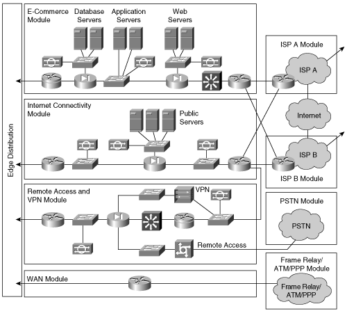
Figure 1-18 illustrates the Enterprise Edge modules.
The E-Commerce module enables enterprises to successfully deploy e-commerce applications and take advantage of the powerful competitive opportunities that are provided by the Internet. Online retail is an example of e-commerce. All e-commerce transactions pass through a series of intelligent services to provide performance, security, scalability, and availability within the overall e-commerce network design.
To build an e-commerce solution, enterprises deploy any of the following types of servers:
Web servers—. Provide the front end to the e-commerce site. Their primary role is to act as a customer interface for the e-commerce site.
Application servers—. Process data and make decisions about the processed data. An example is an application server configured to handle credit card transactions for an online store.
Database servers—. Contain all the information of an e-commerce site. Database servers, for example, may contain data about past records, inventory, or future events. In addition, database information may reside on Fibre Channel SANs because they are increasingly popular in enterprise networks.
Security servers—. Govern communication between the various levels of security in the system, often using firewalls, intrusion detection systems, encryption systems, and access-level control systems.
Any physical server may perform more than one role. For example, a single server may handle web- and application-server roles. Generally, enterprise networks deploy security servers as a separate entity.
The Internet Connectivity module provides internal users with connectivity to Internet services. Internet users can access the information on publicly available servers. Additionally, this module accepts VPN traffic from remote users and remote sites and forwards it to the Remote Access and VPN module. Internet connectivity is crucial in all enterprise networks because it provides a means of communication outside the company.
The major components of the Internet Connectivity module are as follows:
E-mail servers—. Communicate between the Internet and intranet mail servers to exchange corporate e-mail with other companies.
DNS servers—. Act as an authoritative external DNS server for the enterprise and relay internal requests to the Internet. As a result, internal DNS servers replace the need for enterprise networks to connect to Internet DNS servers for domain name resolution. In addition, internal DNS servers may contain additional DNS entries for web services that are only available on the intranet.
Public web servers—. Provide public information about the organization and access to online services such as catalogs and online sales to the Internet.
Security systems—. Govern communication between the various levels of security in the network. Security systems include intrusion detection systems, firewalls, and access control systems such as TACACS+ and RADIUS. Security systems are generally appliances in corporate networks with specific functions; however, servers loaded with special software may act as a security system.
Edge routers—. Impart Layer 3 connectivity to the Internet. Generally, large enterprises deploy multiple Internet edge routers for redundancy. Internet edge routers always use security features such as basic packet filtering, NAT, and a few firewall capabilities. However, the security features deployed on Internet edge routers are not as secure and as sophisticated as security features implemented in the security systems component.
All enterprise networks deploy some methods of remote access. VPN is the most common method of remote access because of the availability of Internet access at home over broadband or DSL networks. Dial-in networks are also available for legacy remote-access methods. The components of the Remote Access and VPN module are as follows:
Dial-in access concentrators—. Terminate and authenticate dial-in connections. Dial-in access is a legacy technology, but it is still a useful method of remote access, especially for remote users who do not have access to a LAN or broadband network. Dial-in access also provides a backup to the other remote-access methods during disaster recovery. An example of a dial-in access concentrator is the Cisco AS5400.
VPN concentrators—. Terminate IP tunnels, forwarded by the Internet Connectivity module, from remote users or remote sites. An example of a VPN concentrator is the Cisco VPN 3000 concentrator. Examples of the VPN client are the Cisco VPN Client (software-based) and Cisco VPN 3002 Hardware Client. Note that Cisco routers may act as VPN clients or concentrators depending on software versions and hardware models.
Firewalls and intrusion detection systems (IDS)—. Firewalls provide network-level protection of resources and stateful filtering of traffic. IDSs detect and protect against unauthorized network traffic within the network.
Layer 2 switches—. Provide Layer 2 connectivity between the devices. Layer 3 switches may also be used in the Remote Access and VPN module but generally are used only as Layer 2 switches because Layer 3 routing is done by the Remote Access or VPN head-in (concentrator) device.
The WAN module routes traffic between the central sites, remote sites, or multiple campuses. The major difference between the WAN module and the Remote Access and VPN module is that with the Remote Access and VPN module, remote users and sites connect over a shared medium such as DSL or cable broadband to the enterprise network, whereas with the WAN module, remote users and sites connect to enterprise networks over point-to-point connections. Examples of these point-to-point connections include physical technologies such as leased lines, optical, cable, DSL, and wireless. Other methods of point-to-point connections include data-link protocols such as Frame Relay, ATM, and Point-to-Point Protocol (PPP). Note that cable and DSL are listed as point-to-point technologies as well. In special configurations, these technologies are able to achieve or emulate point-to-point connections. Moreover, ISDN and dial-up are alternative legacy remote-access options for remote users. Generally, dial-up access for remote users is a backup feature where broadband services are not available.
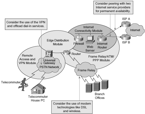
Figure 1-19 shows a sample Enterprise Edge module implementation.
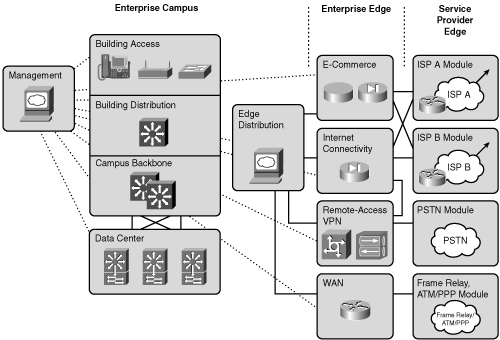
The Service Provider Edge functional area defines modules for the physical connections to ISPs for Internet or intranet connectivity. The Service Provider Edge functional area defines the following three modules:
ISP
Public Switched Telephone Network (PSTN)
Frame Relay, ATM, and PPP
Figure 1-20 illustrates the Service Provider Edge and its modules.
The ISP module enables enterprise connectivity to the Internet. This service is essential to enable Enterprise Edge services, such as the E-Commerce, Remote Access and VPN, and Internet Connectivity modules. To provide redundant connections to the Internet, enterprises connect to two or more ISPs. Physical connections between the ISP and the Enterprise Campus Backbone originate from any WAN technologies.
The PSTN module represents the dial-up infrastructure used to access the enterprise network using ISDN, analog, and wireless (cellular) technologies. Enterprises can also use the PSTN module to back up existing WAN links. Connections are established on demand and are torn down when they are determined to be idle.
The Frame Relay, ATM, and PPP module includes all WAN technologies for permanent connectivity with remote locations. Frame Relay and ATM are common WAN technologies used today. PPP over any medium is another common WAN technology. PPP is used to connect networks across WAN mediums. Metro Ethernet, a MAN technology, is growing in popularity in the WAN as well. Nevertheless, many technologies can fit into the same model.
Figure 1-21 illustrates a sample implementation of the Service Provider Edge functional area.
Cisco Systems, Inc. has recently made a strong push to organize its products in the data center. From an executive point of view, a Cisco Data Center architecture enables IT executives to do the following:
Consolidate and virtualize computing, storage, and network resources
Deliver secure and optimized employee, partner, and customer access to information and applications
Protect and rapidly recover IT resources and applications
At a high level, the Cisco Data Center uses the following network components:
Networked Infrastructure—. Gigabit/10 Gigabit, InfiniBand, storage switching and optical transport
Interactive Services—. Storage Fabric Services, computer services, security services, and application optimization services
Management—. Fabric manager (element and network management) and Cisco VFrame (server and service provisioning)
As with all current enterprise architectures, the Cisco Data Center is based on SONA, which is the enterprise implementation of the IIN technology vision. As discussed previously, Cisco SONA emphasizes the value of the interactive services provided in the networked infrastructure, such as application optimization, security, and server and storage fabric switching, to enhance business applications.
More specifically, the Cisco Data Center is grouped into the following four key areas:
Server Fabrics
Storage Areas Networks/Fabrics
Data Center Interconnects
Access Networks
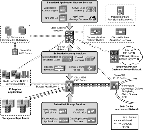
The sections that follow discuss these key areas in more detail. As an example, Figure 1-22 illustrates a sample Cisco Data Center topology.
Server fabrics are used to interconnect servers for the purpose of high-performance cluster computers. To support high-performance clusters, the transport has to be not only high speed but over very low latency.
Applications that use server fabrics include financial modeling, fluid dynamics, and any type of data-mining application. Oracle-SAP and SAS are two popular applications that may benefit from server fabrics.
Currently, a leading data-link technology of interconnecting server fabrics is InfiniBand. InfiniBand is a new technology to financial enterprises but is not new to the scientific community. To achieve the high speed necessary for server fabrics (multiple 10 Gbps) and low latency, the servers using InfiniBand must deploy Remote Direct Memory Access (RDMA), compared with the latent and blocking server PCI bus architecture. An alternative to InfiniBand is, of course, Ethernet. However, Ethernet is not as well suited as InfiniBand for high-performance computing (HPC). As such, there are IEEE drafts discussing a revised Ethernet architecture that can offer RDMA, high performance, and lower latency than traditional Ethernet and low latency loss to InfiniBand. This revised Ethernet architecture has a proposed name of Data Center Ethernet (DCE). Search Google.com for more details on Data Center Ethernet.
The current Cisco products architected for server fabrics are the Cisco SFS 3000 Series Multifabric Server Switches, the Cisco SFS 7000 Series InfiniBand Server Fabric Switches, the Cisco InfiniBand Host Channel Adapters, and blade switches integrated into IBM and Dell blade servers.
SANs consolidate and virtualize storage resources such that the resources can be shared more effectively. Cisco SANs consolidate storage through the use of advanced features such as virtual SANs (VSAN), Fibre Channel over IP (FCIP), SCSI over IP (iSCSI), and Fibre Channel write acceleration. In addition, Cisco SANs enable large heterogeneous networks to support storage services such as virtualization, serverless backup, and continuous data protection, which in turn allow for enhanced business continuance data protection and data migration.
The current Cisco products that are enabling SANs are the Cisco MDS 9000, 9100, 9200, and 9500 director and fabric switches.
The data center interconnect connects the primary data center to a backup or secondary data center over optical or traditional WAN circuits. Data replication and business continuance best practices mandate the need for high-speed, low-latency connections between data center locations. An optical network’s inherent features—low latency, high bandwidth, and high density—are ideal for interconnecting SANs, cluster nodes, and server farms between multiple data centers. When optical networks are not feasible, data center protocols including Fibre Channel can be transported over IP across traditional WANs.
The data center interconnect comprise multiple Cisco products, but primarily the Cisco ONS 15454 and ONS 15000 series and Cisco Catalyst 6500 switches are used in the designs.
The access network secures access to employees, customers, or partners connected remotely over the intranet, Internet, or extranet. The majority of users are not located close to the data center, so robust, secure connectivity to the data center is mandatory. In terms of the Enterprise Composite Network Model, the access network is essentially the campus network.
The remainder of the book focuses primarily on the campus network and not the Data Center aspect of the enterprise. However, the concepts presented are the same ones applied on the front-end IP network of the Data Center design, which includes Catalyst switches in a hierarchical design.
The previous section introduced the building blocks of the Enterprise Composite Network Model. These building blocks include the components of the functional areas of the Enterprise Composite Network Model. This section introduces the Cisco Catalyst switches that are used in the modules and submodules of the Enterprise Composite Network Model. These switches may take on many different roles and are easily adaptable to access, distribution, and core layer roles. These switches are also applicable to any functional area because select models of Catalyst switches offer features such as security and WAN aggregation.
This section specifically covers the following current Cisco switching product lines:
Many other Cisco Catalyst platforms exist and are still shipping; however, the Catalyst 6500, 4500, 4900, 3560, and 2960 families of switches are the most popular switches of today.
Note
The lists of performance, scalability, and availability features per family of switches are abbreviated. For a complete list, consult the Cisco product documentation for each Catalyst family of switches.
The Cisco Catalyst 6500 family of switches is the Cisco elite intelligent multilayer switching platform for delivering secure, converged services from the Building Access to the Campus Backbone of any functional area of the Enterprise Composite Network Model. In addition, the Catalyst 6500 is the leading platform for the core and distribution layers in Data Centers. The Cisco Catalyst 6500 platform uses a modular chassis. Line modules are available in a variety of models, including models with interfaces for 10/100/1000BASE-T Ethernet, Gigabit Ethernet, and 10 Gigabit Ethernet. Interfaces for DS0, OC-3, OC-12, OC-48, and WAN-capable line modules are also available.
The Catalyst 6500 family of switches supports the following features that meet the needs for performance in the enterprise:
Up to 6510 Gigabit Ethernet ports
Hundreds of millions of packets per second for Layers 2 through 4 switching of packets and frames, depending on the Supervisor Engine model and line card models
Distributed CEF architecture
Multiple performance options including 32-Gbps, 256-Gbps, and 720-Gbps bandwidth options with system throughput of 15 million packets per second (mpps), 30 mpps, 210 mpps, or up to 400 mpps
400 Mbps using dCEF720 hardware
Hardware support for enterprise-class and service-provider-scale routing tables for high performance
IPv6 support in hardware using Supervisor Engine 720
Legacy protocol support (such as IPX and DECNET) for specific hardware models
Cisco security solutions, including intrusion detection, firewall, VPN, and SSL at multigigabit speeds
Gigabit Network Analysis Module for remote administration and network monitoring
Available integrated Content Switching Module (CSM) for high-performance, feature-rich server and firewall load balancing
Cisco Firewall Services Module (FWSM) offers unsurpassed firewall and virtualization services
GRE support and Layer 2 bridging support in hardware at 400 mpps
Hardware-assisted NAT support
NBAR network management and control support at gigabit speeds
With regard to scalability, the Catalyst 6500 family of switches embraces the following characteristics:
Forward-thinking architecture with investment protection
Available in a 3-, 6-, 9-, and 13-slot modular chassis
Up to 1152 10/100/1000BASE-T Ethernet ports per chassis using RJ-45 or RJ-21
Multiple Gigabit and 10 Gigabit trunk ports per chassis
Data and voice integration with 802.3af Power over Ethernet (PoE)
MPLS support
Support for up to 1,000,000 IPv4 routes and 500,000 IPv6 routes in hardware
Support for up to 128,000 NetFlow entries
Support for Layer 3 classification, aggregate rate limiting, and flow-based rate limiting
Available dense T1/E1 and Foreign Exchange Station (FXS) VoIP gateway interfaces for PSTN access and traditional phone, fax, and PBX connections
LAN, WAN, and MAN convergence
Long product life cycle
Application-Oriented Networking (AON)
In terms of availability, the Catalyst 6500 supports network high availability through features such as spanning tree and HSRP, and it supports component redundancy such as dual supervisor, dual route processors, and dual switch fabrics. The following list summarizes the major high-availability features of the Catalyst 6500 family of switches:
Nonstop Forwarding and Stateful Switchover (NSF/SSO)
Cisco IOS Software Modularity
Designed for redundancy
HSRP and VRRP
802.1D/802.1s/802.1w Spanning-Tree redundancy
802.3ad and EtherChannel link redundancy
Highly available, stateful protocol redundancy
Cisco IOS Software redundancy
Individual component redundancy
Dual, redundant Supervisor Engines
Redundant switching fabrics
Redundant power supplies
Intelligent network services redundancy
Redundant clocking system
Redundant fan system
In terms of security, the Catalyst 6500 family of switches offers the following features in addition to the features mentioned previously. (Later chapters explain these features in more detail.)
Denial-of-service (DoS) attack mitigation
Security Service Modules
Man-in-the-middle attack mitigation
Identity Based Networking Services (IBNS)
Access list counters for monitoring traffic using specific details
Port security
IEEE 802.1x and 802.1x extensions for access-based security
VLAN and router ACLs and Port ACLs for traffic filtering
Security ACL entries
Reflexive ACLs
Unicast Reverse Path Forwarding (uRPF) check in hardware for multicast forwarding protection
CPU rate limiters for DoS protection
Private VLANs for host-to-host protection
Support for large number interfaces with unique ACLs
MAC ACLs on IP
TCP intercept hardware acceleration
The Catalyst 4500 and 4900 families of switches serve primarily as Building Access or Building Distribution switches in the Campus Infrastructure. The members of the 4900 family of switches are the Catalyst 4948 and Catalyst 4948-10GE. The Cisco Catalyst 4948-10GE switch offers 48 ports of wire-speed 10/100/1000BASE-T with 2 ports of wire-speed 10 Gigabit Ethernet (X2 optics). The Catalyst 4948-10GE switch is becoming extremely popular as an access-layer switch in the campus for host workstations and in the data center for server aggregation. In terms of performance, the 10GE model supports up to 102 mpps and 136 Gbps.
In reference to the Catalyst 4500 family of switches, the leading-edge supervisor is the Supervisor Engine V-10GE, which also supports up to 102 mpps and 136 Gbps in throughput performance.
In remote offices, these switches may function as the sole switch or as a Campus Backbone switch in a small network of only a few switches. In ISP networks, these switches are designed for business services aggregation and subscriber access in the metropolitan area because of the Cisco Long-Reach Ethernet capabilities of the platform.
In terms of performance, the Catalyst 4500 family of switches accommodates up to 64 Gbps or 48 mpps at Layer 2, 3, or 4 using the CEF-based hardware architecture of the Supervisor III or IV Engine. The Supervisor Engine V-10GE is capable of 136 Gbps and 102 mpps. The Supervisor II+ is only Layer 2 capable but is able to switch at 64 Gbps.
For the Catalyst 4500 family of switches, the following list indicates the scalabilities of the platform:
3-, 6-, 7-, and 10-slot modular chassis
Integrates voice, video, and data
Up to 336 10/100/1000BASE-T Gigabit Ethernet ports in a 10-slot chassis
Integrated inline power for IP phones
Multiple Gigabit Ethernet trunks
WAN edge support through a specialized module
802.1Q-in-Q
In terms of high availability, the Catalyst 4500 supports the following features:
Nonstop Forwarding with Stateful Switchover (NSF/SSO)
HSRP and VRRP
802.1D/802.1s/802.1w spanning-tree redundancy
802.3ad and EtherChannel link redundancy
Redundant Supervisor Engines for the Supervisor II+, IV, and V with 7-slot or 10-slot chassis
Power supply redundancy
In terms of security, the Catalyst 4500 supports the following features:
Network access control (NAC)
Storm Control
Per-Port QoS
Standard and extended ACLs on all ports
802.1x user authentication (with VLAN assignment, voice VLAN, port security, and guest VLAN extensions)
802.1x accounting
Trusted boundary
Router ACLs (RACL) on all ports (no performance penalty)
VLAN ACLs (VACL)
Port ACLs (PACL)
Private VLANs (PVLAN) on access and trunk ports
DHCP snooping and Option 82 insertion
Port security
Sticky port security
VLAN Management Policy Server (VMPS) client
Unicast MAC filtering
Unicast port flood blocking
Dynamic ARP inspection
IP source guard
Community VLANs
Voice VLAN sticky-port security
The Cisco Catalyst 3560 family of switches, generally deployed as Building Access switches, offers fixed port density with similar features to high-end switches but at a lower cost. The previous generation 3550 and 3750 switches can be grouped into the 3560 category, minus a few features.
Despite the lower cost associated with these switches, they support many switching features, including QoS, security, IP routing, and access control. These switches are available in fixed port configurations of 10/100BASE-T Fast Ethernet, 10/100/1000BASE-T Gigabit Ethernet, and Gigabit Ethernet over fiber interfaces. The Cisco Catalyst 3560 Series differs from the Catalyst 3550 in that it offers IEEE 802.3af and Cisco pre-standard PoE functionality in Fast Ethernet and Gigabit Ethernet configurations.
Note
For the remainder of this book, any mention of the Catalyst 3560 family of switches refers to the Catalyst 3550 and 3750 families of switches as well, unless otherwise stated.
In terms of performance, the 3560 supports up to 32 Gbps of traffic forwarding at Layer 2 or Layer 3 and supports jumbo frames up to 9018 bytes. Despite having fixed port densities, the Catalyst 3560 family supports the following scalabilities features:
Baby Giants
Up to 48 10/100 Fast Ethernet ports or 48 10/100/1000 Gigabit Ethernet Ports (3750G models)
Integration for voice, video, and data
Inline power for IP phones that adhere to the 802.3af standards
Support for Cisco GigaStack or StackWise technology for switch stacking
In terms of availability, the Catalyst 3560 family of switches does not support component redundancy; however, the Catalyst 3560 family of switches does support the following availability features:
HSRP and VRRP
1:N stateful redundancy for stack forwarding redundancy (Catalyst 3750 only)
802.1D/802.1s/802.1w spanning-tree redundancy
802.3ad and EtherChannel link redundancy
Power supply redundancy through an external Redundant Power Supply (RPS)
In terms of security, the Catalyst 3560 switches offer the following security features:
802.1x.
MAC address-based port security.
Cisco security VLAN ACLs (VACLs) on all VLANs to prevent unauthorized data flows to be bridged within VLANs.
Cisco standard and extended IP security Router ACLs (RACL) define security policies on routed interfaces for control plane and data plane traffic.
Port-based ACLs (PACL) for Layer 2 interfaces allow security policies to be applied on individual switch ports.
Time-based ACLs allow the implementation of security settings during specific periods of the day or days of the week.
Private VLAN edge provides security and isolation between ports on a switch, ensuring that users cannot snoop on other users’ traffic.
User-selectable address-learning mode simplifies configuration and enhances security.
The Cisco Catalyst 2960 family of switches, also generally deployed as Building Access switches, offers fixed port density with similar features to high-end switches but at a lower cost. Despite the lower cost associated with these switches, they support many advanced switching features including integrated security, NAC, advanced QoS, and resiliency.
These switches are available as 24 or 48 10/100 or 10/100/1000BASE-T ports with dual-purpose uplinks for Gigabit Ethernet uplink flexibility, allowing use of either a copper or a fiber uplink—each dual-purpose uplink port has one 10/100/1000 Ethernet port and one Small Form-Factor Pluggable (SFP)-based Gigabit Ethernet port, with one port active at a time.
Note
The Catalyst 2950, 2955, and 2970 family of switches can be grouped into the same category as the Catalyst 2960 family of switches. The Catalyst 2960 family is the current-generation platform; the former switches (2950, 2955, and 2970) support a similar subset of features, QoS, NAC, security, and so on.
In terms of performance, the Catalyst 2960 family of switches offers the following features:
Wire-speed Fast Ethernet and Gigabit Ethernet Layer 2 switching
32-Gbps switching fabric
ACL and QoS Layer 2 and Layer 3 features at wire-speed Fast Ethernet and Gigabit Ethernet
Jumbo Ethernet support of up to 9000-byte frames
With regard to the scalability of the platform, the Catalyst 2960 family of switches includes the following features:
Up to 48 10/100 Fast Ethernet interfaces and 2 dual-purpose Gigabit Ethernet ports
Support for 10/100/1000BASE-T Gigabit Ethernet, 100BASE-FX Fast Ethernet, and Gigabit Ethernet
Configurable up to 8000 MAC addresses
Integrated Cisco IOS Software features for bandwidth optimization
Granular rate limiting
As for reliability, the Catalyst 29560 family supports the following availability features:
Bandwidth aggregation up to 8 Gbps through Cisco Gigabit EthernetChannel technology
802.1D/802.1s/802.1w Spanning-Tree redundancy
802.3ad and EtherChannel link redundancy
Power supply redundancy through an external RPS
In terms of security, the Catalyst 2960 family supports the following security features:
802.1x and a plethora of 802.1x advanced features
MAC address notification
Private VLAN edge
Port Security
Port-Based Access Control (based on MAC address, IP address, or TCP/UDP port)
DHCP Interface Tracker and DHCP snooping
TACACS+ and RADIUS authentication
Port-based ACLs for Layer 2 interfaces, allowing application of security policies on individual switch ports
SSHv2 and SNMPv3, providing network security by encrypting administrator traffic during remote-access and SNMP sessions
In terms of manageability, the Catalyst 2960 family supports the following manageability features:
Cisco IOS CLI.
Cisco Service Assurance Agent (SAA) support facilitates service-level management throughout the LAN.
Switching Database Manager templates for security and QoS allow administrators to easily adjust memory allocation to the desired features based on deployment-specific requirements.
Cisco Network Assistant is a no-charge, Windows-based application that simplifies the administration of networks of up to 250 users. It supports a wide range of Cisco Catalyst intelligent switches. With Cisco Network Assistant, users can manage Cisco Catalyst switches and launch the device managers of Cisco integrated services routers and Cisco Aironet WLAN access points.
Express Setup simplifies initial configuration of a switch through a web browser, eliminating the need for terminal-emulation programs and CLI knowledge.
CiscoWorks network-management software provides management capabilities on a per-port and per-switch basis, providing a common management interface for Cisco routers, switches, and hubs.
The following bullets review important BCMSN certification exam preparation points of this chapter. The bullets briefly highlight only the main points of this chapter related to the BCMSN exam and should be used only as supplemental study material. Consult the text of this chapter for additional information regarding these topics. Table 3-9 lists important commands to review for the BCMSN certification exam.
Cisco SONA provides the framework for today’s Internet business solutions. Moreover, Cisco SONA provides the baseline infrastructure that enables enterprises to design networks that scale to meet Internet business demands for performance, security, availability, and scalability. Cisco IIN is the future vision of the Cisco enterprise network.
The functional areas of the Enterprise Composite Network Model represent specific modeling points of the Enterprise Campus network.
Each functional area of the Enterprise Composite Networks is composed of its own Catalyst switches in a hierarchical model.
The hierarchical model includes the Building Access submodule (access layer), Building Distribution submodule (distribution layer), and Campus Backbone submodule (core layer).
Implementing the hierarchical model is unique for each enterprise, and the design is dependent on performance, scalability, availability, and security requirements.
Layer 2 switching is defined as forwarding frames based on MAC address only. However, Layer 2 switches may support Layer 3 features such as QoS marking.
Layer 3 switching involves forwarding frames based on IP addresses.
The term multilayer switching (MLS) describes a switch designed to perform both Layer 2 and Layer 3 switching functions on a single platform.
Layer 4 through 7 switching involves advanced IP features such as TCP/UDP access control lists and content intelligence.
The Data Center has evolved as a separate entity that used to be logically referred to as the Server Farm. The Data Center includes not only the IP network but also the high-performance computing infrastructure and the back-end storage.
Cisco SONA is an enterprise-wide, standards-based network architecture that provides a road map for combining business and technology strategies into a cohesive model. The Enterprise Composite Network Model provides a modular framework for designing networks built on the premise of Cisco SONA. The modularity model allows flexibility in network design and facilitates implementation and troubleshooting.
The following list summarizes the key concepts of the Enterprise Composite Network Model:
The Cisco Service-Oriented Network Architecture (SONA) is an architectural framework that guides your evolution to an Intelligent Information Network to accelerate applications, business processes, and profitability. This comprehensive framework provides guidelines to help you evolve your IT infrastructure and transform your business processes with network investments that increase business growth, agility, efficiency, and productivity.
The Cisco Intelligent Information Network (IIN) is a strategy that addresses the evolving role of the network within your business and directly addresses your desire to align IT resources with business priorities. The resulting network delivers active participation, process optimization, service delivery, and application responsiveness, which results in better IT awareness.
The Enterprise Composite Network Model comprises the Enterprise Campus, Enterprise Edge, and Service Provider Edge functional areas.
The functional areas of the Enterprise Composite Network Model represent specific modeling points of the enterprise network.
The Enterprise Campus functional area includes the Campus Infrastructure, Network Management, and Edge Distribution modules.
The Enterprise Edge functional area includes the E-Commerce, Internet Connectivity, Remote Access and VPN, and WAN modules.
Each module of the Enterprise Edge functional area connects to the Edge Distribution module, which connects the Enterprise Edge and the Campus Backbone.
The Service Provider Edge includes the ISP, PSTN, and Frame Relay/ATM/PPP module.
All modules of the Enterprise Composite Network Model are composed of their own access, distribution, and core layers.
The Enterprise Composite Network Model functional areas consist of Cisco Catalyst switches. Each Cisco Catalyst switch supports a varying degree of performance, scalability, and availability. Selecting the appropriate Cisco Catalyst switch depends on the needs for performance, scalability, availability, and other design principles, including cost.
For multiple-choice questions, there might be more than one correct answer.
True or False: If you are not deploying security features in your multilayer switched network, network security (and your job) is at risk. | |||||||||
True or False: Security is the single most important aspect of designing multilayer switched networks. | |||||||||
True or false: Hardware-switching of frames provides for additional scalability in switching platforms. | |||||||||
True or False: The Enterprise Composite Network Model creates modularity for the hierarchical network design model of access, distribution, and core layers. | |||||||||
True or False: In large enterprise networks, the Enterprise Data Center is its own functional area, combining the IP network, high-performance computer, and back-end storage-area networks. | |||||||||
Denote each switching feature as a Layer 2, 3, 4, or 7 switching feature and property.
| |||||||||
Which of the following is not a Layer 2 switching feature? You may need to consult later chapters for guidance in answering this question.
| |||||||||
Match each Enterprise Composite Network Model functional area to a description.
| |||||||||
Match each Enterprise Campus module to a description.
| |||||||||
Match each Enterprise Edge module to a description.
| |||||||||
Match each Service Provider Edge module with its description.
| |||||||||
Which of the following switches support(s) IP routing?
| |||||||||
Which of the following switches is well suited for metro Ethernet deployments because of its Long-Reach Ethernet functionality?
| |||||||||
Which of the following switches support(s) highly available power via redundant power?
| |||||||||
Which of the following switches use(s) a modular architecture?
| |||||||||
Which of the following switches supports ATM interfaces natively?
| |||||||||
Which of the following switches is well suited for any role in the Enterprise Composite Network Model regardless of network size?
| |||||||||
What are the advantages of using modular switches rather than fixed port density switches?
| |||||||||
Which of the following features applies modular switch benefits to fixed port density switches?
| |||||||||
In Figure 1-23, Workstation A is sending a frame to Workstation B. Assuming that all ARP tables are complete with correct entries, what is the destination MAC address of the frame destined for Workstation B at Location A? | |||||||||
In Figure 1-23, Workstation A is sending a frame to Workstation B. Assuming all ARP tables are complete with correct entries, what is the source MAC address, destination MAC address, and destination IP address of the frame destined for Workstation B at Location B? | |||||||||
In Figure 1-23, Workstation A is sending a frame to Workstation B. Assuming all ARP tables are complete with correct entries, what is the source MAC address, the destination MAC address, and the source IP address of the frame destined for Workstation B at Location C? |
