This chapter covers the following topics:
Using Techniques to Enhance Performance
Monitoring Performance with SPAN and VLAN SPAN
Monitoring Performance with Remote SPAN
Monitoring Performance with Enhanced Remote SPAN
Monitoring Performance Using VLAN ACL with the Capture Option
Troubleshooting Using L2 Traceroute
Enhancing Troubleshooting and Recovery Using Cisco IOS Embedded Event Manager
Employing the Network Analysis Module for the Catalyst 6500 Family of Switches
Previous chapters described troubleshooting methodology applied to Cisco multilayer switched networks. For you to be able to perform these complex troubleshooting and performance analyses, Cisco provides software and hardware tools to help you monitor and analyze the traffic on your network, which is the first step to optimizing performance. Traffic monitoring allows you to identify bottlenecks, underused resources, and places where you may implement improvements such as port aggregation (increasing link bandwidth by combining several physical ports into a single virtual link). Optimizing the performance of your Cisco multilayer switched network helps to maximize use of existing resources and reduces unnecessary duplication of network components. This ensures that the network runs efficiently and supports multiple solutions. This chapter explains some of the most commonly used features to monitor and understand performance and aid in troubleshooting Cisco multilayer switched networks.
This chapter covers these multilayer switch performance and troubleshooting tools and features with a brief description of each feature’s functionality and its support on various switches. Each section also includes a small case study on how to use these tools in real network troubleshooting scenarios using Cisco CatOS–and Cisco IOS–based switches. Upon completion of this chapter, you will understand how to use these tools to effectively monitor performance and troubleshoot network issues in a Cisco multilayer switched network.
Performance management includes maintaining internetwork performance at acceptable levels by measuring and managing various network performance variables. This section covers some of the techniques used to enhance network performance.
Critical performance-management issues are as follows:
User/application performance—. For most users, response time is the critical performance success factor. This variable may shape the perception of network success by both your users and application administrators.
Capacity planning—. Capacity planning is the process of determining future network resource requirements to prevent a performance or availability impact on business-critical applications.
Proactive fault management—. Fault management involves both responding to faults as they occur and implementing solutions that prevent faults from affecting performance.
The critical success tasks that need to be performed for performance management are as follows:
Gather a baseline for both network and application data.
This step aids in troubleshooting performance issues during network operations. A typical router or switch baseline report would include capacity issues related to CPU, memory, buffer management, link utilization, and throughput. In addition, there are other types of baseline data that need to be included depending on your defined objectives. For instance, an availability baseline would demonstrate increased stability and availability of the network environment. Perform a baseline comparison between old and new environments to verify solution requirements. Develop a good network topology diagram as part of this step.
Perform a what-if analysis on your network and applications.
A what-if analysis involves modeling and verifying solutions. Before adding a new solution to the network, document some of the alternatives. The documentation for this analysis includes major questions, methodology, data sets, and configuration files. The essential what-if analysis should contain enough information for someone other than the author to re-create the solution.
Perform exception reporting for capacity issues.
If capacity requirements outstrip available resources, there should be in place a mechanism to notify network administrators of that fact. This could include setting up periodical SNMP polling on some key parameters of the network devices, such as CPU and memory, and having the network management station alert the administrator in the event of anomalous behavior.
Determine the network management overhead for all proposed or potential network management services.
Network management services affect network and application performance. Make sure that the network measurement planning takes into account the additional resources required to perform measurement and management. For instance, SNMP polling of devices needs CPU cycles from the switch or router. If the device is already running at an above-average CPU utilization, the management services may further strain the device. In addition, the bandwidth required for these management functions should be considered if the links are heavily utilized to avoid oversubscription.
Analyze the capacity information.
Examine all the data you have gathered to determine capacity and management requirements. This is the most important task, forming the basis for the next step.
Periodically review capacity information, baseline, and exceptions for the network and applications.
Periodically repeat your analysis to identify changes in network use and growth patterns. The time interval chosen for measurement depends on the nature of the network being measured, and it may vary over weekdays versus weekends and also on a monthly or yearly basis. Reviewing the capacity periodically is critical to avoid unexpected network or application downtime and to plan for future growth.
Maintain upgrade or tuning procedures that are set up to handle capacity issues on both a reactive and longer-term basis.
Set up procedures to handle future capacity requirements. For instance, if you think that your network may need another link addition to a port channel based on certain thresholds, make sure that you plan for this change. Having the cabling and configuration procedure in place in advance minimizes the time required to make the change and ensures that the network runs smoothly without major downtime.
This section outlined some best-practice tasks essential for good performance management. The remainder of this chapter focuses on the various Cisco Catalyst switches and modules that assist in performance management and troubleshooting network exceptions.
The Switched Port Analyzer (SPAN) feature is an important aid in performance management and troubleshooting. SPAN copies network traffic from a VLAN or group of ports to a selected port. This port is usually connected to a network analyzer, such as a SwitchProbe device, a workstation running a packet-capturing application, or a remote monitoring (RMON) probe. SPAN does not affect the switching of network traffic on source ports or VLANs.
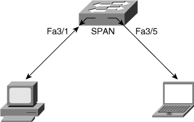
Local SPAN involves configuring source ports, source VLANs, and destination ports on the same Catalyst switch. Local SPAN, which involves configuring one or more VLANs as the source of the SPAN session, is also called VSPAN. All ports in the source VLANs become source ports in a VSPAN. Local SPAN copies traffic from one or more source ports in any VLAN or from one or more VLANs to a destination port for analysis. For example, as shown in Figure 17-1, the switch copies all traffic transmitted to and from port 3/1 (the source port) to port 3/5 (the destination port). A workstation running a packet-capturing application on port 3/5 thus receives all network traffic received and transmitted on port 3/1.
SPAN sessions support the monitoring of only ingress network traffic (ingress SPAN), only egress network traffic (egress SPAN), or traffic flowing in both directions. Ingress SPAN copies network traffic received by the source ports and VLANs for analysis to the destination port. Egress SPAN copies network traffic transmitted from the source ports and VLANs to the destination port. When the both keyword is used, SPAN copies the network traffic received and transmitted by the source ports and VLANs to the destination port.
By default, local SPAN monitors all network traffic, including multicast and bridge protocol data unit (BPDU) frames.
Note
On a Cisco CatOS–based Catalyst switch, it is possible to disable multicast traffic monitoring from the source ports or VLAN. On Cisco IOS–based switches, this feature is currently not available, but Catalyst 4500 switches provide destination port filters using ACLs to remove any unneeded traffic for monitoring.
SPAN supports the configuration of both switched and routed ports as SPAN source ports. SPAN can monitor one or more source ports in a single SPAN session. Configuring source ports in any VLAN is allowed. Trunk ports are valid source ports mixed with nontrunk source ports. However, trunk encapsulation (dot1q or ISL) configuration of the destination port determines the encapsulation of the packets forwarded to the destination port. If the destination port is not configured for trunk encapsulation, the ISL or dot1q is removed from the frame before egress transmission. Refer to Chapter 4, “Implementing and Configuring VLANs,” for more details on trunk encapsulations.
Note
In Cisco IOS–based Catalyst switches, you must dedicate the destination port for SPAN use because the port does not learn MAC addresses. For the Catalyst 2950, 3550, 4000, and Catalyst 4500 families of switches, it is possible for the device connected on the destination port to send traffic to the switch. The switch forwards these incoming frames out to the other ports based on the destination MAC address and IP address. An intrusion prevention system (IPS) typically uses the ingress feature on the destination port to thwart attacks in the network by sending TCP resets to the attacker TCP session or sending alarms to network management stations. In later Cisco IOS versions, Catalyst switches can be configured to dynamically learn MAC addresses on the destination SPAN port using the learning keyword.
The following additional guidelines or restrictions apply to local SPAN:
Both Layer 2 switched ports (LAN ports configured with the switchport command) and Layer 3 ports (LAN ports configured with the no switchport command) can be configured as source or destination ports in Cisco IOS–based switches.
A port can act as the destination port for only one SPAN session.
A port cannot be configured as a destination port if it is a source port of a span session.
Port channel interfaces (EtherChannel) can be configured as source ports:
A member port of an EtherChannel configured as a SPAN source port transitions into the suspended state and carries no traffic on Cisco IOS–based Catalyst 6500 with releases earlier than Cisco IOS 12.1(13)E.
Active member ports of an EtherChannel cannot be configured as source ports on Cisco IOS–based Catalyst 6500 with Cisco IOS 12.1(13)E and later releases. Inactive member ports of the EtherChannel go into suspended state if they are configured as source ports and carry no traffic.
A port channel interface (EtherChannel) cannot be a destination port:
A member port of an EtherChannel configured as a SPAN destination port goes into suspended state and carries no traffic with releases earlier than Cisco IOS 12.1(13)E.
Active member ports of an EtherChannel cannot be configured as destination ports on Cisco IOS–based Catalyst 6500 with Cisco IOS 12.1(13)E and later releases. Inactive member ports of the EtherChannel go into suspended state if they are configured as destination ports and carry no traffic.
SPAN supports configuration of source ports belonging to different VLANs.
Local SPAN uses any previous configuration when enabled in Cisco CatOS. Always check for a previous configuration before enabling SPAN in Cisco CatOS to avoid unwarranted situations. For instance, the prior configuration SPAN destination port may now be connected to another switch. By enabling SPAN, the SPAN session results in loss of connectivity to the new switch or possible Spanning Tree Protocol (STP) issues.
Traffic direction is “both” by default for SPAN sources.
Destination ports never participate in a spanning-tree instance. Local SPAN includes BPDUs in the monitored traffic, so any BPDUs seen on the destination port are from the source port. As a result, SPAN destination ports should not be connected to another switch, because this may cause a network loop.
Destination ports get a copy of all packets switched through the switch regardless of whether or not the packets actually leave the switch due to STP blocking state on an egress port.
The following additional guidelines or restrictions apply to VSPAN:
VSPAN sessions, with both ingress and egress options configured, forward duplicate packets from the source port only if the packets get switched in the same VLAN. One copy of the packet is from the ingress traffic on the ingress port, and the other copy of the packet is from the egress traffic on the egress port.
VSPAN only monitors traffic that leaves or enters Layer 2 ports in the VLAN:
Routed traffic that enters a monitored VLAN is not captured if the SPAN session is configured with that VLAN as an ingress source, because traffic never appears as ingress traffic entering a Layer 2 port in the VLAN.
Traffic that is routed out of a monitored VLAN, which is configured as an egress source in a SPAN session, is not captured because the traffic never appears as egress traffic leaving a Layer 2 port in that VLAN.
The destination port of SPAN can be configured with the inpkts keyword option in Cisco CatOS–based switches, which allows the destination port to receive packets from the network analyzer device and forward the packets to other ports in the switch. In Cisco IOS–based switches, the ingress vlan keyword is used instead of the inpkts keyword. The inpkts or ingress vlan features are useful when the monitoring station, such as an intrusion detection system, needs to send TCP resets upon TCP attack detection in the network. Table 17-1 shows the support of this feature in various Catalyst switches. The inpkts option is also useful for remotely accessing network analyzers.
Table 17-1. Support of the inpkts/ingress vlan Feature on Catalyst Switches
Catalyst Switch | inpkts/ingress vlan Feature (Minimum Software Version) |
|---|---|
Catalyst 2950/Catalyst 2955 | 12.1(13)EA1 |
Catalyst 3550 | 12.1(12c)EA1 |
Catalyst 3750/Catalyst 3560 | All versions |
Catalyst 4500 Cisco IOS family | 12.1(19)EW |
Catalyst 6500 Cisco CatOS family | 5.1 |
Catalyst 6500 Cisco IOS family | 12.2(33)SXH |
Example 17-1 shows the configuration and verification of a local SPAN session on a Cisco CatOS–based switch. The source port is 3/1, and the destination port is 3/21. The SPAN session is configured to only capture traffic in the receive direction on the source port. In addition, destination port 3/21 is configured for the inpkts and learning optional features.
Example 17-1. Local SPAN Configuration and Verification on Cisco CatOS–Based Switches
6500> (enable)  set span 3/1 3/21 rx inpkts enable learning enable
2003 May 04 20:46:02 %SYS-5-SPAN_CFGSTATECHG:local span session active for
destination port 3/21
Destination      : Port 3/21
Admin Source     : Port 3/1
Oper Source      : None
Direction        : receive
Incoming Packets : enabled
Learning         : enabled
Multicast        : enabled
Filter           : -
Status           : active
Warning: The destination port will not participate in the spanning tree protocol and
may cause spanning tree loops.
6500> (enable)  show span
Destination      : Port 3/21
Admin Source     : Port 3/1
Oper Source      : None
Direction        : receive
Incoming Packets : enabled
Learning         : enabled
Multicast        : enabled
Filter           : -
Status           : active
Total local span sessions:  1
On Cisco IOS–based switches, use the following commands in configuration mode to configure local SPAN.
monitor session session source {interface interface-id | vlan vlan-id [,][-] {rx | tx | both} monitor session session destination interface interface-id [encapsulation {dot1q | isl}][ingress vlan vlan-id]
Example 17-2 shows the configuration and verification of a local SPAN session on a Cisco IOS–based switch. The source interface is FastEthernet 3/1, and the destination interface is FastEthernet 3/21.
Example 17-2. Local SPAN Configuration and Verification on Cisco IOS–Based Catalyst Switches
4506(config)#monitor session 1 source interface FastEthernet 3/1
4506(config)#monitor session 1 destination interface FastEthernet 3/21
4506(config)#end
1d01h: %SYS-5-CONFIG_I: Configured from console by bsivasub on console
4506#show monitor session 1
Session 1
----------
Type              : Local Session
Source Ports      :
    Both          : Fa3/1
Destination Ports : Fa3/21
    Encapsulation : Native
          Ingress : Disable
Example 17-3 shows the configuration and verification of a VSPAN session for capturing traffic on a Cisco CatOS–based Catalyst switch. This VSPAN only captures traffic in the receive (rx) direction for VLAN 10 and VLAN 20. The destination port for this VSPAN session is 3/21.
Example 17-3. VSPAN Configuration and Verification on Cisco CatOS–Based Catalyst Switches
6500> (enable)  set span 10,20 3/21 rx
2003 May 04 21:08:32 %SYS-5-SPAN_CFGSTATECHG:local span session active for
destination port 3/21
Destination     : Port 3/21
Admin Source    : VLAN 10,20
Oper Source     : None
Direction       : receive
Incoming Packets: disabled
Learning        : enabled
Multicast       : enabled
Filter          : -
Status          : active
6500> (enable)  show span
Destination     : Port 3/21
Admin Source    : VLAN 10,20
Oper Source     : None
Direction       : receive
Incoming Packets: disabled
Learning        : enabled
Multicast       : enabled
Filter          : -
Status          : active
Total local span sessions:  1
Note
Cisco CatOS–based Catalyst switches do not allow source ports to have different characteristics with regard to direction of traffic in SPAN sessions. In Cisco IOS–based switches, it is possible for different source ports to have different directions of traffic in SPAN sessions.
Example 17-4 shows the configuration of a VSPAN session on a Cisco IOS–based Catalyst switch with rx-only traffic for VLAN 10, and tx-only traffic for VLAN 20 and destination port interface FastEthernet 3/4.
Example 17-4. VSPAN Configuration and Verification on Cisco IOS–Based Catalyst Switches
cat4k(config)#monitor session 1 source vlan 10 rx
cat4k(config)#monitor session 1 source vlan 20 tx
cat4k(config)#monitor session 1 destination interface FastEthernet 3/4
cat4k#show monitor session 1
Session 1
---------
Type               : Local Session
Source VLANs       :
    RX Only        : 10
    TX Only        : 20
 Destination Ports : Fa3/4
     Encapsulation : Native
           Ingress : Disabled
The sc0 interface represents the management interface of the Supervisor Engine on switches running CatOS. The ability to span the sc0 interface is available on all Cisco CatOS switches with the exception of the Catalyst 4000 and 4500 families of switches.
Note
Currently, only Catalyst 4500 Cisco IOS–based switches support an equivalent CPU monitoring feature among the Cisco IOS–based switches. The Catalyst 6500 family of switches plans to support CPU monitoring in Cisco IOS Release 12.2(33)SXH.
The ability to span the CPU comes in handy when you are trying to troubleshoot traffic destined to the CPU of the Supervisor Engine. Traffic destined to the Supervisor Engine includes the control traffic, such as BPDUs, SNMP traffic, and so on. Normal switch traffic is not forwarded to the CPU and is handled via hardware switching. Captured traffic also includes Telnet traffic and broadcast traffic seen in the same subnet as the Supervisor Engine.
To configure SPAN to monitor the sc0 interface, enter the following command:
 set span sc0 {mod/dest_port} [rx | tx | both] [inpkts {enable | disable}] [learning
  {enable | disable}] [multicast {enable | disable}] [filter vlans] [create]
Example 17-5 illustrates a user configuring a SPAN session to monitor the sc0 interface with the SPAN destination port as 3/27.
Example 17-5. Configuration and Verification of SPAN Session to Switch CPU Port (sc0)
cat6k> (enable)  set span sc0 3/27
2003 Apr 28 17:54:08 %SYS-5-SPAN_CFGSTATECHG:local span session active for
destination port 3/27
Destination     : Port 3/27
Admin Source    : Inband Port (sc0)
Oper Source     : Inband Port (sc0)
Direction       : transmit/receive
Incoming Packets: disabled
Learning        : enabled
Multicast       : enabled
Filter          : -
Status          : active
To configure a SPAN to monitor the CPU traffic on the Catalyst 4000 and 4500 Cisco IOS–based switches, use the keyword cpu in the monitor session source configuration, as shown in Example 17-6.
Example 17-6. Configuration and Verification of SPAN to Monitor the CPU Port on Catalyst 4000 and 4500 Cisco IOS–Based Switches
4506(config)# monitor session 1 source cpu ?
  both    Monitor received and transmitted traffic
  queue   SPAN source CPU queue
  rx      Monitor received traffic only
  tx      Monitor transmitted traffic only
  <cr>
4506(config)# monitor session 1 source cpu queue ?
  <1-32>          SPAN source CPU queue numbers
  acl             Input and output ACL [13-20]
  adj-same-if     Packets routed to the incoming interface [7]
  all             All queues [1-32]
  bridged         L2/bridged packets [29-32]
  control-packet  Layer 2 Control Packets [5]
  mtu-exceeded    Output interface MTU exceeded [9]
  nfl             Packets sent to CPU by netflow (unused) [8]
  routed          L3/routed packets [21-28]
  rpf-failure     Multicast RPF Failures [6]
  span            SPAN to CPU (unused) [11]
  unknown-sa      Packets with missing source address [10]
4506(config)# monitor session 1 source cpu
4506(config)#monitor session 1 destination interface fastEthernet 3/21
4506(config)#end
1d00h: %SYS-5-CONFIG_I: Configured from console by bsivasub on consmonitor session 1
4506#show monitor session 1
Session 1
---------
Type              : - Source Ports      :
    Both          : CPU Destination Ports : Fa3/21
    Encapsulation : Native
          Ingress : Disabled
This case study provides a practical scenario to illustrate the use of the SPAN session sourcing the sc0 interface in troubleshooting network issues. The switch in this case study is displaying the following error messages in the console and syslog:
 %IP-3-UDP_SOCKOVFL:UDP socket 161 overflow
 %IP-3-UDP_SOCKOVFL:UDP socket 161 overflow
The switch generates this syslog message when the buffer allocated for incoming packets on the specified socket (UDP destination port) is full because the rate of traffic destined for that socket is too high for the switch to process. If the switch generates an excessive number of these messages, use a network analyzer to identify the source of the traffic and reduce the rate of traffic.
Because this is a well-known port for SNMP polling, it is most likely that the polling frequency needs to be reduced. To confirm this theory, the administrator connects the network analyzer to the switch and configures a SPAN session with the sc0 interface as the source. After analyzing the captured output, the administrator determines that a device in his network is sending an excessive amount of unauthorized SNMP polling queries to the switch. When the device is disabled, the switch stops reporting the error messages.
Tip
It is recommended to configure the capture filter in the network analyzer to narrow the capture only to traffic destined to a particular source or destination or a type of traffic. This greatly reduces the time required to analyze the captured data for interesting traffic and reduces the amount of buffer space required to capture the frames. In addition, using display filters in the analyzer helps to better analyze the captured frames.
Remote SPAN (RSPAN) is similar to SPAN, but it supports source ports, source VLANs, and destination ports on different switches, which provide remote monitoring of multiple switches across a switched network. Each RSPAN session carries the SPAN traffic over a user-specified RSPAN VLAN. This VLAN is dedicated for that RSPAN session in all participating switches.
The RSPAN source ports can be trunks carrying the RSPAN VLAN. Local SPAN and RSPAN do not monitor the RSPAN traffic in the RSPAN VLAN seen on a source trunk. For example, if the source port carries VLAN 1 through 10, with 10 being the RSPAN VLAN, the local span of that port does not mirror the RSPAN traffic to the destination port. However, the local SPAN correctly monitors traffic for the other VLANs 1 through 9. To receive the RSPAN traffic on a destination port, the port must be configured as the RSPAN destination port for that RSPAN VLAN.
The destination ports in the RSPAN VLAN receive RSPAN traffic from the source ports or source VLANs. The source ports or VLANs in an RSPAN session may be different on different source switches, but they must be the same for all sources on each RSPAN source switch. Each RSPAN source switch must have either ports or VLANs as RSPAN sources.
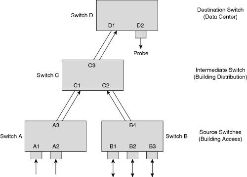
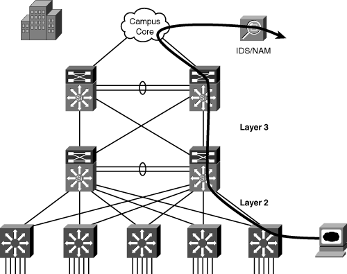
Figure 17-2 shows an RSPAN configuration across multiple switches. Access switches A and B act as the RSPAN source, distribution switch C acts as the intermediate switch, and data center switch D acts as the RSPAN destination switch where the probe is connected. Without RSPAN, the user has to go to each of the closet switches and manually configure local SPAN to monitor the traffic. For example, the administrator charged with monitoring ports A1 and A2 has to configure a local SPAN session on switch A and then configure a separate local SPAN session to monitor ports B1, B2, and B3. This type of configuration is obviously not scalable for geographically separated switch closets; RSPAN enables the administrator to monitor these remote ports from the data center switch. In this case, the trunks between the switches carry RSPAN VLAN traffic for the RSPAN to work correctly.
RSPAN consists of an RSPAN source session, an RSPAN VLAN, and an RSPAN destination session. It is advisable to configure separate RSPAN source sessions and destination sessions on different network devices. To configure an RSPAN source session on one network device, associate a set of source ports and VLANs with an RSPAN VLAN. To configure an RSPAN destination session on another device, associate the destination port with the RSPAN VLAN.
In addition to the guidelines and restrictions that apply to SPAN, these guidelines apply to RSPAN:
Configure the RSPAN VLANs in all source, intermediate, and destination network devices. If enabled, the VLAN Trunking Protocol (VTP) can propagate configurations of VLANs numbered 1 through 1024 as RSPAN VLANs. Manually configure VLANs numbered higher than 1024 as RSPAN VLANs on all source, intermediate, and destination network devices.
Network devices that support RSPAN VLANs can act as an RSPAN intermediate device.
Switches impose no limit on the number of RSPAN VLANs configured.
Intermediate switches might impose limits on the number of RSPAN VLANs that they can support, depending on their capacity. For instance, some low-end switches like Catalyst 2950 support only 250 VLANs with the Enhanced Image software image.
RSPAN VLANs carry only RSPAN traffic.
Do not configure a VLAN used to carry management traffic as an RSPAN VLAN.
Do not assign access ports to RSPAN VLANs.
Do not configure ports in an RSPAN VLAN except those selected to carry RSPAN traffic.
RSPAN VLAN has MAC address learning disabled.
RSPAN source ports and destination ports must reside on different network devices.
RSPAN does not support BPDU monitoring.
Do not configure RSPAN VLANs as sources in VSPAN sessions.
Configure any VLAN as an RSPAN VLAN as long as all participating network devices support configuration of RSPAN VLANs and use the same RSPAN VLAN for each RSPAN session.
Entering SPAN configuration commands does not clear previously configured SPAN parameters. Enter the no monitor session command to clear previously configured SPAN parameters.
RSPAN configuration involves the following two steps:
Configure the RSPAN VLAN in the VTP server. This VLAN is then dedicated for RSPAN. If VTP transparent mode is used, configure RSPAN in all the devices in the domain consistently.
Configure the RSPAN session in the source and destination switches and ensure that the intermediate switches carry the RSPAN VLAN across respective VLAN trunks. Table 17-2 shows software support of the RSPAN feature on different Catalyst families of switches.
Table 17-2. Support of RSPAN Feature on Catalyst Switches
Catalyst Switch | RSPAN (Minimum Software Version) |
|---|---|
Catalyst 2950/Catalyst 3550 | 12.1(11)EA1 |
Catalyst 2955 | All versions |
Catalyst 3750/Catalyst 3560 | All versions |
Catalyst 4500 Cisco IOS family | 12.1(20)EW |
Catalyst 6500 Cisco CatOS family | 5.3 |
Catalyst 6500 Cisco IOS family | 12.1(13)E |
On Cisco IOS–based Catalyst switches, use the following commands in configuration mode to configure RSPAN.
On the source switch:
monitor session session source {interface interface-id | vlan vlan-id} [,][-] {rx | tx |
On the destination switch:
 monitor session session source remote vlan vlan-id
 monitor session  session destination interface  interface-id [encapsulation {dot1q
 |
 isl}] [ingress vlan vlan-id]
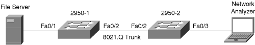
Example 17-7 shows the configuration and verification of an RSPAN session between two Catalyst 2950 switches. Switch 2950-1 is the source switch for the RSPAN session, and 2950-2 is the destination switch with the network analyzer. Only the Catalyst 2950 and Catalyst 2955 series switches require an additional port to be designated as the reflector port. The reflector should be left unconnected and is used internally by the Catalyst 2950 for implementing RSPAN. In Example 17-7, the reflector port is interface FastEthernet 0/24. The reflector port is used on the Catalyst 2950 switches as a way to overcome the limitation of that switch architecture in regards to SPAN. Figure 17-3 depicts the network scenario for this example.
Example 17-7. RSPAN Configuration and Verification on Cisco IOS–Based Catalyst Switches
2950-1(config)# vlan 100
2950-1(config-vlan)#remote-span
2950-1(config-vlan)#exit
2950-1(config)#monitor session 1 source interface FastEthernet 0/1
2950-1(config)#monitor session 1 destination remote vlan 100 reflector-port
FastEthernet 0/24
2950-1(config)#in FastEthernet 0/21
2950-1(config-if)#switchport mode trunk
2950-1(config-vlan)# end
2950-1#
___________________________________________________________________________________
2950-2(config)#monitor session 2 source remote vlan 100
2950-2(config)#monitor session 2 destination interface FastEthernet 0/3
2950-2(config)#in FastEthernet 0/2
2950-2(config-if)#switchport mode trunk
2950-2(config-vlan)#end
2950-2#
___________________________________________________________________________________
2950-1# show monitor
Session 1
---------
Type              : Remote Source Session
Source Ports      :
    Both          : Fa0/1
Reflector Port    : fa0/24
Dest RSPAN VLAN   : 100
2950-1#show interfaces trunk
Port        Mode         Encapsulation  Status        Native vlan
Fa0/2       on           802.1q         trunking      1
Port      Vlans allowed on trunk
Fa0/2       1-4094
Port        Vlans allowed and active in management domain
Fa0/2       1-30,100
Port        Vlans in spanning tree forwarding state and not pruned
Fa0/2       1-30,100
___________________________________________________________________________________
2950-2#show interfaces trunk
Port        Mode         Encapsulation  Status        Native vlan
Fa0/2       on           802.1q         trunking      1
Port      Vlans allowed on trunk
Fa0/2       1-4094
Port        Vlans allowed and active in management domain
Fa0/2       1-30,100
Port        Vlans in spanning tree forwarding state and not pruned
Fa0/2       1-30,100
2950-2#show monitor session 2
Session 2
---------
Type              : Remote Destination Session
Source RSPAN VLAN : 100
Destination Ports : Fa0/3
    Encapsulation : Native
          Ingress : Disabled
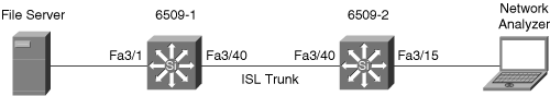
Example 17-8 shows the configuration and verification of an RSPAN session between two Catalyst 6500 switches running Cisco CatOS. Switch 6509-1 is the source switch for the RSPAN session and 6509-2 is the destination switch with the network analyzer. Figure 17-4 depicts the network scenario for this example.
Example 17-8. RSPAN Configuration and Verification on Cisco CatOS–Based Catalyst Switches
6509-1> (enable)  set vlan 100  rspan
VTP advertisements transmitting temporarily stopped,
and will resume after the command finishes.
Vlan 100 configuration successful
6509-1> (enable)  set rspan source 3/1 100
Rspan Type       : Source
Destination      : - Rspan Vlan      : 100
Admin Source     : Port 3/1
Oper Source      : None
Direction        : transmit/receive
Incoming Packets : - Learning        : -
Multicast        : enabled
Filter           : -
Status           : active
6509-1> (enable) 2003 May 06 21:18:47 %SYS-5-SPAN_CFGSTATECHG:remote span source
session active for remote span vlan 100
6509-1> (enable)  set trunk 3/40 isl desirable
Port(s)  3/40 trunk mode set to desirable.
________________________________________________________________________________
6509-2> (enable)  set trunk 3/40 isl desirable
Port(s)  3/40 trunk mode set to desirable.
6509-2> (enable) set rspan destination 3/15 100
2003 May 06 21:20:07 %SYS-5-SPAN_CFGSTATECHG:remote span destination session active
for destination port 3/15
Rspan Type      : Destination
Destination     : Port 3/15
Rspan Vlan      : 100
Admin Source    : - Oper Source     : - Direction       : -
Incoming Packets: disabled Learning        : enabled Multicast       : -
Filter          : - Status          : active
________________________________________________________________________________
6509-1> (enable)  show rspan
Rspan Type      : Source Destination     : -
Rspan Vlan      : 100
Admin Source    : Port 3/1
Oper Source     : None
Direction       : transmit/receive
Incoming Packets: - Learning        : - Multicast       : enabled Filter          : -
Status          : active
Total remote span sessions:  1
___________________________________________________________________________________
6509-2> (enable) show rspan
Rspan Type      : Destination
Destination     : Port 3/15
Rspan Vlan      : 100
Admin Source    : - Oper Source     : - Direction       : -
Incoming Packets: disabled Learning        : enabled Multicast         : -
Filter          : - Status          : active
Total remote span sessions:  1
___________________________________________________________________________________
6509-1> (enable)  show trunk 3/40
* - indicates vtp domain mismatch
# - indicates dot1q-all-tagged enabled on the port
Port      Mode         Encapsulation  Status        Native vlan
-------  -----------  -------------  ------------  -----------
 3/40     desirable    isl            trunking      1
Port      Vlans allowed on trunk
-------  ------------------------------------------------------------------------
 3/40     1-1005,1025-4094
Port      Vlans allowed and active in management domain
-------  -----------------------------------------------------------------------
 3/40     1,10,20,100
Port      Vlans in spanning tree forwarding state and not pruned
-------  -----------------------------------------------------------------------
 3/40     1,10,20,100
________________________________________________________________________________
6509-2> (enable)  show trunk 3/40
* - indicates vtp domain mismatch
# - indicates dot1q-all-tagged enabled on the port
Port      Mode         Encapsulation  Status        Native vlan
--------  -----------  -------------  ------------  -----------
 3/40     desirable    isl            trunking      1
Port      Vlans allowed on trunk
--------  -----------------------------------------------------------------
 3/40     1-1005,1025-4094
Port      Vlans allowed and active in management domain
--------  -----------------------------------------------------------------
 3/40     1,10,20,100
Port      Vlans in spanning tree forwarding state and not pruned
--------  -----------------------------------------------------------------
 3/40      1,10,20,100
Enhanced Remote SPAN (ERSPAN) is similar to RSPAN, but it supports source ports, source VLANs, and destination ports on different switches, even across the Layer 3 boundary, which provides remote monitoring of multiple switches across a switched or routed network. Each ERSPAN session carries the SPAN traffic over a GRE tunnel. The source and destination switches must support GRE in hardware. Currently, the ERSPAN feature is supported only on the Catalyst 6500 family of switches.
To configure an ERSPAN source session on one switch, you associate a set of source ports or VLANs with a destination IP address, ERSPAN ID number, and, optionally, a VRF name. To configure an ERSPAN destination session on another switch, you associate the destination ports with the source IP address, ERSPAN ID number, and, optionally, a VRF name.
ERSPAN source sessions do not copy locally sourced RSPAN VLAN traffic from source trunk ports that carry RSPAN VLANs. ERSPAN source sessions do not copy locally sourced ERSPAN GRE-encapsulated traffic from source ports.
Each ERSPAN source session can have either ports or VLANs as sources, but not both.
The ERSPAN source session copies traffic from the source ports or source VLANs and forwards the traffic using routable GRE-encapsulated packets to the ERSPAN destination session. The ERSPAN destination session switches the traffic to the destination ports, as shown in Figure 17-5.
The following guidelines and restrictions apply to ERSPAN:
The payload of a Layer 3 ERSPAN packet is a copied Layer 2 Ethernet frame, excluding any ISL or 802.1Q tags.
ERSPAN adds a 50-byte header to each copied Layer 2 Ethernet frame and replaces the 4-byte cyclic redundancy check (CRC) trailer.
ERSPAN supports jumbo frames that contain Layer 3 packets of up to 9202 bytes. If the length of the copied Layer 2 Ethernet frame is greater than 9170 bytes (9152-byte Layer 3 packet), ERSPAN truncates the copied Layer 2 Ethernet frame to create a 9202-byte ERSPAN Layer 3 packet.
Regardless of any configured MTU size, ERSPAN creates Layer 3 packets that can be as long as 9202 bytes. ERSPAN traffic might be dropped by any interface in the network that enforces an MTU size smaller than 9202 bytes.
With the default MTU size (1500 bytes), if the length of the copied Layer 2 Ethernet frame is greater than 1468 bytes (1450-byte Layer 3 packet), the ERSPAN traffic is dropped by any interface in the network that enforces the 1500-byte MTU size.
All ERSPAN source sessions on a switch must use the same origin IP address, configured with the origin ip address command.
All ERSPAN destination sessions on a switch must use the same IP address on the same destination interface. You enter the destination interface IP address with the ip address command.
ERSPAN configuration involves the following two steps:
Example 17-9 shows the configuration and verification of ERSPAN on the source and destination switches.
Example 17-9. ERSPAN Configuration and Verification on a Catalyst 6500 Switch
Switch1(config)#monitor session 66 type erspan-source
Switch1(config-mon-erspan-src)#source interface gigabitethernet 6/1
Switch1(config-mon-erspan-src)#destination
Switch1(config-mon-erspan-src-dst)#ip address 10.10.10.10
Switch1(config-mon-erspan-src-dst)#origin ip address 20.20.20.200
Switch1(config-mon-erspan-src-dst)#erspan-id 111

Switch1#show monitor session 66
Session 66
----------
Type                   : ERSPAN Source Session
Status                 : Admin Enabled
Source Ports           :
    Both               : Gi6/1
Destination IP Address : 10.10.10.10
Destination ERSPAN ID  : 111
Origin IP Address      : 20.20.20.200
________________________________________________________________________
Switch2(config)#monitor session 60 type erspan-destination
Switch2(config-erspan-dst)#destination interface gigabitethernet 6/1
Switch2(config-erspan-dst)#source
Switch2(config-erspan-dst-src)#ip address 10.10.10.10
Switch2(config-erspan-dst-src)#erspan-id 111
Switch2#show monitor session 60
Session 60
----------
Type                   : ERSPAN Destination Session
Status                 : Admin Enabled
Destination Ports      : Gi6/1
Source IP Address      : 10.10.10.10
Source ERSPAN ID       : 111
The number of supported local SPAN, RSPAN, and ERSPAN sessions varies on different Catalyst switches. Table 17-3 provides a summary of the number of local and remote SPAN sessions supported on Cisco CatOS–based Catalyst families of switches, and Table 17-4 provides the summary for Cisco IOS–based Catalyst switches.
Table 17-4. Summary of SPAN/RSPAN Session Support on Cisco IOS–Based Catalyst Switches
Feature | Catalyst 3750 | Catalyst 4500 | Catalyst 6500 (Cisco IOS) |
|---|---|---|---|
rx or both SPAN sessions | 2 | 2 | 2 |
tx SPAN sessions | 2 | 4 | 2 (16 with 12.2 [33] SXH) |
rx, tx, or both RSPAN source sessions | 6 (2 rx, 4 tx or 2 both, 2 tx) | 1 (with 1 rx SPAN session) | 1 (with 1 rx SPAN session) |
RSPAN destination | 2 | 2 | 64 |
ERSPAN destination | — | — | 23 |
Total sessions | 2 | 6 | 89 |
The Catalyst 6500 family of switches offers an additional feature to monitor traffic flows through the switch. SPAN, VSPAN, and RSPAN configuration applies to all traffic on the source port or source VLAN in one or both directions. Using VACLs with the capture option, the network analyzer only receives a copy of traffic matching the configured ACL. Because the ACL may match Layer 2, 3, or 4 information, the VACL with the capture option offers a useful and powerful complementary value to the SPAN and RSPAN features.
The VACL with the capture option on the Catalyst 6500 family of switches also overcomes the session number limit, as listed in Table 17-3 and Table 17-4, thus increasing the monitoring capability. The VACL with capture option works by a user setting up a VACL to match the interesting traffic and then configuring the capture port, which receives the copy of the matched traffic.
The following configuration guidelines apply to using the capture option in VACL:
The capture port cannot be an ATM port.
The capture port needs to be in the spanning-tree forwarding state for the VLAN.
The switch has no restriction on the number of capture ports.
The capture port captures only packets permitted by the configured ACL.
Capture ports only transmit traffic belonging to the capture port VLAN. To capture traffic going to many VLANs, configure the capture port as a trunk carrying the required VLANs.
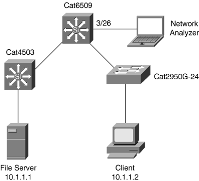
In Figure 17-6, a user is troubleshooting a session timeout between a server and client. Example 17-10 shows the user configuring VACL with the capture option to monitor communication between a client and a server on Cisco CatOS–based Catalyst switches.
Example 17-10. Configuration and Verification of VACL with the Capture Option on Cisco CatOS–Based Catalyst 650
cat6k> (enable)   set security acl ip bcmsn_VACL permit ip host 10.1.1.1 host
  10.1.1.2 capture
bcmsn_VACL editbuffer modified. Use 'commit' command to apply changes.
cat6k> (enable)   set security acl ip bcmsn_VACL permit ip host 10.1.1.2 host
10.1.1.1 capture
bcmsn_VACL editbuffer modified. Use 'commit' command to apply changes.
cat6k> (enable)  commit security acl bcmsn_VACL
ACL commit in progress.
ACL 'bcmsn_VACL' successfully committed.
cat6k> (enable)  set security acl map bcmsn_VACL 1
Mapping in progress.
ACL bcmsn_VACL successfully mapped to VLAN 1.
cat6k> (enable)  set security acl capture-ports 3/26
Successfully set 3/26 to capture ACL traffic.
cat6k> (enable)  show security acl info all
set security acl ip bcmsn_VACL
-----------------------------------------------------
arp permit
1. permit ip host 10.1.1.1 host 10.1.1.2 capture
2. permit ip host 10.1.1.2 host 10.1.1.1
capture cat6k> (enable)  show security acl capture-ports
ACL Capture Ports: 3/26
Example 17-11 shows the VACL with the capture option configuration and verification for the troubleshooting scenario presented in Figure 17-5 on the Cisco IOS–based Catalyst 6500 family of switches.
Refer to the VACL section in Chapter 14, “Securing Your Multilayer Switched Network to Minimize Service Loss and Data Theft,” for additional information about various VACL configuration options.
Example 17-11. Configuration and Verification of VACL with the Capture Option on Cisco IOS–Based Catalyst 6500
cat6k(config)# access-list 101 permit ip host 10.1.1.1 host 10.1.1.2
cat6k(config)# access-list 101 permit ip host 10.1.1.2 host 10.1.1.1
cat6k(config)#vlan access-map bcmsnvacl
cat6k(config-access-map)#match ip address 101
cat6k(config-access-map)#action forward capture
cat6k(config-access-map)# exit
cat6k(config)# vlan filter bcmsnvacl vlan-list 1
cat6k(config)#in GigabitEthernet 3/26
cat6k(config-if)#switchport
cat6k(config-if)#switchport capture allowed vlan 1
cat6k(config-if)#switchport capture
cat6k(config-if)#end
cat6k#show vlan access-map
Vlan access-map "bcmsnvacl"  10
         match: ip address 101
        action: forward capture
cat6k#show vlan filter
VLAN Map bcmsnvacl:
        Configured on VLANs:  1
            Active on VLANs:  1
Layer 2 (L2) traceroute is equivalent to the IP traceroute command except that this trace is for Layer 2 connectivity troubleshooting based on MAC addresses. L2 traceroute is a powerful tool for determining the path of a frame through the Layer 2 topology. The administrator needs to know only the source and destination MAC addresses of the devices in question. L2 traceroute also identifies the physical connection of any device in the network, freeing the administrator from having to manually check each switch.
To illustrate a typical troubleshooting scenario, consider a situation in which the connection between a server and client is slow. To troubleshoot this problem, identify the source and destination IP addresses of this session. Once the IP addresses are determined, you can easily find the MAC address of these devices by consulting the ARP tables of the workstation, client, and adjacent routers. Next, you need to locate the ports where the actual client and server are connected in the Layer 2 infrastructure. If, however, the L2 topology is large, it may be difficult to find out where these two devices are connected with just their IP addresses and MAC addresses unless the ports are clearly labeled and the network is clearly organized.
L2 traceroute is useful in these situations to trace the device connection into the network using just the MAC addresses. The L2 traceroute command also works with IP addresses being specified as part of the command for directly connected subnet devices. In the case of Cisco CatOS switches, the devices that you are troubleshooting must reside in the same subnet as the sc0 or sl0 interface. In the case of Cisco IOS switches, the devices being traced must be in the same subnet as any of the switched virtual interfaces (SVI) configured on those switches.
Many Catalyst families of switches support L2 traceroute. Table 17-5 shows the availability on various Catalyst switches.
Table 17-5. L2 Traceroute Availability on Catalyst Switches
Catalyst Switch | L2 Traceroute (Minimum Software Version) |
|---|---|
Catalyst 2950 | 12.1(12c)EA1 |
Catalyst 2955 | All versions |
Catalyst 3550 | 12.1(12c)EA1 |
Catalyst 3560/3750 | All versions |
Catalyst 4500 | 12.1(13)EW |
Catalyst 6500 Cisco CatOS family | 6.1 |
Catalyst 6500 Cisco IOS family | 12.2(18)SXE |
L2 traceroute requires the following conditions to function properly:
All the switches and interfaces in the network require CDP to be running and functioning properly.
All intermediate switches between the source and device in question must support the L2 traceroute feature. Refer to Table 17-5 for a list of switches and software supporting this feature.
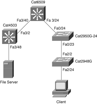
In Figure 17-7, a user needs to identify the performance and path on a hop-by-hop basis for a specific server and client exhibiting slow file-transfer performance. Example 17-12 shows a user using the L2 traceroute feature with the source MAC address of the server, 0000.0000.0007, to the destination MAC address of the client, 0000.0000.0011. To perform L2 tracerouting, the user may choose any switch in the network as long as that switch has both the source and destination MAC addresses in the MAC address table. In this example, the user performed the L2 traceroute command on the Catalyst 2950 of Figure 17-7.
Example 17-12. L2 traceroute Output from Cisco IOS–Based Switches
2950G#traceroute mac 0000.0000.0007 0000.0000.0011
Source 0000.0000.0007 found on 4503
4503 (14.18.2.132) : Fa3/48 => Fa3/2
6500 (14.18.2.145) :  3/40 =>  3/24
2950G (14.18.2.176): Fa0/24 => Fa0/23
2948G (14.18.2.91) :  2/2 =>  2/24
Destination 0000.0000.0011 found on 2948G Layer 2 trace completed
Example 17-13 shows the same user using the L2 traceroute feature from the same source and destination as in the previous example; this time, however, the commands were executed from the Catalyst 2948G switch running Cisco CatOS software. Figure 17-7 shows the network topology for this example’s output.
The output from the L2 traceroute helps the user focus on troubleshooting the links between the source and destination devices without the user having to worry about building a network diagram or the spanning-tree topology.
To summarize, L2 traceroute is useful and applicable to any switch in the network in determining the path from any source to any destination. This feature offers flexibility and reduces time in troubleshooting individual host issues in large networks.
The Embedded Event Manager (EEM) feature has the capability to monitor events happening in the switch using embedded event collectors. The events tracked could be a generation of a syslog message, incrementing of a certain counter, or the result of a Generic Online Diagnostic (GOLD) test. Based on the detection of these events, custom actions could be performed, including configuration changes, e-mail notification, or paging the system administrator. The EEM feature is currently available only on the Catalyst 6500 switches running Modular IOS Software. Cisco plans to introduce this feature in future releases of other Catalyst switches. EEM is available in Cisco routers starting in Cisco IOS Software Release 12.2(18)SXF4.
EEM greatly improves troubleshooting and recovery of network failures by providing the capability not only to detect a great variety of events in the switch but also to take immediate actions without user invention.
Table 17-6 shows a sample set of events and typical actions that can be automated with EEM. It is important to remember that actions based on an event are fully user configurable.
Table 17-6. Sample EEM Scenarios
Event (User Configurable) | Action (User Defined) |
|---|---|
A specific interface error crosses a user-defined threshold. | Disable the interface and bring up a backup interface. |
Configuration changes are made during production hours. | Deny the configuration changes and send an e-mail alert. |
A GOLD diagnostic test fails. | Generate a custom syslog message indicating the action to take for Level 1 network operators. |
A user logs into the system. | Generate a custom login message based on the user ID. |
Unauthorized hardware is removed or added from the switch. | Send a page to the administrator. |
It is necessary to collect data for capacity planning. | Run a user-defined set of commands to collect the capacity information at regular intervals. |
The EEM feature on Catalyst 6500 is configurable in the following two ways:
EEM using applet CLI—. Cisco IOS CLI–based configuration that provides a limited set of actions and detection
EEM using Tool Command Language (TCL) script—. Provides full flexibility in defining the events and the subsequent actions
EEM allows customers to define their own custom TCL script that can be executed on the Catalyst switch. For more information about EEM, refer to the following documentation on Cisco.com (requires a Cisco.com username and password):
“Embedded Event Manager 2.0” http://www.cisco.com/en/US/partner/products/sw/iosswrel/ps1838/products_feature_guide09186a008025951e.html
The Network Analysis Module (NAM) for the Cisco Catalyst 6500 family of switches is part of the end-to-end network management and monitoring solution. Network administrators need to collect statistics about voice, video, and data applications. The NAM gathers multilayer information about voice, video, and data flows up through the application layer, helping to simplify the task of managing multiservice switched LANs that support a variety of data, voice, and video applications.
The NAM monitors and analyzes network traffic using RMON, RMON extensions for switched networks, and other Management Information Bases (MIB).
Cisco has three NAM versions:
WS-X6380-NAM—. The first-generation NAM. It has a connection only to the data bus with no fabric connections.
WS-SVC-NAM-1—. A second-generation NAM with higher performance and a dual-processor architecture. It is scalable to support large switching environments running up to gigabit speeds. NAM-1 consists of 512-MB RAM with a 96-MB capture buffer.
WS-SVC-NAM-2—. Another second-generation NAM. In addition to NAM-1, NAM-2 has another accelerator card that provides extra-high packet-processing performance for full-scale gigabit monitoring. NAM-2 consists of 1-GB RAM with a 128-MB capture buffer.
The embedded NAM Traffic Analyzer software in the NAM gives any web browser access to the RMON1 (RFC 1757), RMON2 (RFC 2021), SMON (RFC 2613), DSMON (RFC 3287), and voice-monitoring features of the NAM. Furthermore, the NAM software provides the ability to troubleshoot and monitor network availability and health.
In addition to extensive MIB support, the NAM can also monitor individual Ethernet VLANs, which allows the NAM to serve as an extension to the basic RMON support provided by the Catalyst Supervisor Engine.
The TrafficDirector application, or any other IETF-compliant RMON application, can access link, host, protocol, and response-time statistics for capacity planning and real-time application protocol monitoring. Filters and capture buffers are also available for troubleshooting the network.
The NAM requires the following basic configuration via root access before use:
IP address
Subnet mask
IP broadcast address
IP host name
Default gateway
Domain name
DNS name server, if a domain name service is used
If you are using an external SNMP manager to communicate with the NAM, configure the following:
SNMP MIB variables
Access control for the SNMP agent
System group settings on the NAM
The web server (using the ip http server enable command)
Example 17-14 shows the configuration and verification of the basic parameters on the WS-X6380-NAM. Use the root account to configure these parameters. The default login for the root account is root, and the password is root. Change the default password for this root account before beginning configuration.
Example 17-14. Configuration and Verification of Basic Parameters on the NAM
root@localhost#password
Changing password for user root
New UNIX password:
Retype new UNIX password:
passwd: all authentication tokens updated successfully
root@localhost#ip address 14.18.2.190 255.255.255.0
root@localhost#ip broadcast 14.18.2.255
root@localhost#ip host cat6knam
root@cat6knam#ip gateway 14.18.2.21
root@cat6knam#ip domain cisco.com
[email protected]#ip nameserver 14.18.2.200
[email protected]# show ip
IP address:          14.18.2.190
Subnet mask:         255.255.255.0
IP Broadcast:        14.18.2.255
DNS Name:            cat6knam.cisco.com
Default Gateway:     14.18.2.21
Nameserver(s):       14.18.2.200
HTTP server:         Disabled
HTTP secure server:  Disabled
HTTP port:           80
HTTP secure port:    443
TACACS+ configured:  No
Exsession:           Off
[email protected]#snmp location 1stFloor
[email protected]#snmp contact JohnDoe
[email protected]#snmp name cat6k
[email protected]#snmp community cisco rw
[email protected]#snmp community cisco123 ro
[email protected]#show snmp
SNMP Agent:   cat6knam.cisco.com    14.18.2.190
SNMPv1:  Enabled SNMPv2C: Enabled SNMPv3:  Disabled
community   cisco    write community   cisco123  read community   private  write
community   public   write community   ww       write
sysDescr         Catalyst 6000 Network Analysis Module (WS-X6380-NAM)
sysObjectID      enterprises.9.5.1.3.1.1.2.223
sysContact       JohnDoe sysName          cat6k sysLocation      1stFloor
The NAM supports having multiple data sources simultaneously. The NAM can use the following data sources for traffic analyses:
Ethernet, Fast Ethernet, Gigabit Ethernet, trunk port, or Fast EtherChannel; SPAN or RSPAN source port; VSPAN and VACL with the capture option.
Locally generated NetFlow Data Export (NDE) records. The NDE feature collects individual flow statistics of the traffic switched through the switch. NDE can also export the collected information to external flow collectors such as the NetFlow FlowCollector application. The NAM is another example of such a flow collector.
Note
With NDE records as source, the NAM only monitors the protocol (RMON2 protocol distribution table), the host (RMON2 nlHost and alHost tables), and the conversation (RMON2 nlMatrix and alMatrix tables) collection types. NDE records have insufficient information to implement other collection types.
To configure SPAN as a traffic source, use the CLI or NAM Traffic Analyzer application. Example 17-15 shows a user configuring a VSPAN source for the NAM in slot 4 of a Cisco IOS–based Catalyst 6500 switch.
Example 17-15. User Configuration and Verification of VSPAN with NAM Port as Destination on Cisco IOS–Based Catalyst 6500 Switch
Cat6kIOS(config)#monitor session 1 source vlan 10
Cat6kIOS(config)#monitor session 1 destination interface GigabitEthernet 4/1
Cat6kIOS(config)#end
Cat6kIOS#show monitor
Session 1
---------
Source Ports:
RX Only: None
TX Only: None
Both: None
Source VLANs:
RX Only: None
TX Only: None
Both: 10
Destination Ports:Gi4/1
Filter VLANs: None
Example 17-16 shows the user configuring and verifying a SPAN configuration for the NAM in slot 4 of a Cisco CatOS–based Catalyst 6500 switch.
Example 17-16. Configuration and Verification of SPAN to NAM Port in Cisco CatOS–Based Catalyst 6500 Switch
6500> (enable)  set span 2/1 4/1 both create
Destination      : Port 4/1
Admin Source     : Port 2/1
Oper Source      : None
Direction        : transmit/receive
Incoming Packets : disabled
Learning         : enabled
Multicast        : enabled
Filter           : -
Status           : active
6500> (enable) 2003 May 10 18:50:15 %SYS-5-SPAN_CFGSTATECHG:local span session
active for destination port 4/1
6500> (enable)  show span
Destination      : Port 4/1
Admin Source     : Port 2/1
Oper Source      : None
Direction        : transmit/receive
Incoming Packets : disabled
Learning         : enabled
Multicast        : enabled
Filter           : -
Status           : active
Total local span sessions:  1
To use NDE as a traffic source for the NAM, enable the NetFlow Monitor option to allow the NAM to receive the NDE stream. The NAM receives NDE statistics automatically.
NDE makes traffic statistics available for analysis by an external data collector. Use NDE to optionally monitor all Layer 3 switched traffic and all routed IP unicast traffic.
When configuring the NAM as an NDE collector, use only the IP address of the NAM on the Cisco IOS–based Catalyst 6500 family of switches.
Example 17-17 shows a user configuring the NAM IP address as the NDE destination on a Catalyst 6500 switch running Cisco IOS. The mls nde sender command enables the NDE export feature on the PFC for exporting statistics for Layer 3 switched traffic. The ip route-cache flow interface-level command enables NetFlow switching so that statistics are collected for NDE export.
Example 17-17. Enabling NDE as Source for NAM on Cisco IOS–Based Catalyst 6500 Switches
Cat6kIOS(config)#mls nde sender
Cat6kIOS(config)#mls rp nde-address 14.18.2.190
Cat6kIOS(config)#mls flow ip full
Cat6kIOS(config)#mls nde flow include protocol udp
Cat6kIOS(config)#ip flow-export destination 14.18.2.190 3000
Cat6kIOS(config)#ip flow-export source vlan 1
Cat6kIOS(config)#interface vlan 10
Cat6kIOS(config-if)#ip route-cache flow
Example 17-18 shows a user configuring NDE as a source for the NAM in Cisco CatOS–based Catalyst switches.
Example 17-18. Enabling NDE as Source for NAM on Cisco CatOS–Based Catalyst 6500 Switches
6500> (enable)  set snmp extendedrmon netflow enable 4
Snmp extended RMON netflow enabled to module 4
6500> (enable)  show snmp
SNMP:                       Enabled
RMON:                       Disabled
Extended RMON Netflow Enabled : Module 4
Memory usage limit for new RMON entries: 85 percent
EngineId: 00:00:00:09:00:30:7b:4e:34:00:00:00
Chassis Alias: Traps Enabled: None
Port Traps Enabled: None
Community-Access     Community-String
----------------     ---------------------
read-only            public
read-write           private
read-write-all       secret
Additional-                         Access-
Community-String      Access-Type   Number  View
____________________ ______________ _______ __________________________________
Trap-Rec-Address Trap-Rec-Community Trap-Rec-Port Trap-Rec-Owner Trap-Rec-Index
________________ __________________ _____________ ______________ ______________
6500> (enable)  set mls nde enable
Netflow export to Network Analysis Module
6500> (enable) 2003 May 10 19:01:12 %MLS-5-NDEENABLED:Netflow Data Export enabled
The autostart command is used on NAM initialization to configure several RMON collections on every available data source (including all known VLANs). Alternatively, RMON collections may be explicitly configured through SNMP by a management station on only some data sources. Collections that are explicitly configured through SNMP take precedence over autostart collections, so if both are configured, only the explicitly configured collections are started on each data source when the NAM initializes.
The NAM allows the automatic starting of the following collection types:
addressMap—. addressMapTable from RMON2-MIB (RFC 2021)
art—. artControlTable from draft-warth-rmon2-artmib-01.txt
etherStat—. etherStatsTable from RMON-MIB (RFC 1757)
prioStats—. smonPrioStatsControlTable from SMON-MIB (RFC 2613)
vlanStats—. smonVlanStatsControlTable from SMON-MIB (RFC 2613)
Note
For data sources that are already configured through SNMP, the autostart collection type configuration does not apply.
To enable or disable autostart collection, use the autostart collection {enable | disable} command.
To enable etherStat and vlanStat autostart collections, respectively, issue the following command:
 [email protected]#autostart etherstats enable
 [email protected]#autostart vlanstats enable
To disable etherStat and vlanStat autostart collections, respectively, issue the following command:
 [email protected]#autostart etherstats disable
 [email protected]#autostart vlanstats disable
Note
If the autostart collection configuration is enabled or disabled, the NAM requires rebooting for the new configuration to take effect.
The application response time (ART) MIB measures the response time on the network at the transport layer. ART MIB can be enabled and disabled globally using the rmon artmib {enable | disable} privileged command. To enable ART MIB, use the following:
[email protected]#rmon artmib enable
Note
An ART MIB license from Cisco Systems must be purchased before enabling and using the ART MIB feature.
To verify the NAM configuration, use the show commands from the NAM console. The commonly used show commands are as follows:
show ip—. Displays the IP configuration of the NAM and HTTP server status.
show snmp—. Displays the community strings and SNMP MIB variables.
show options—. Specifies whether ART MIB and voice monitoring are enabled.
show autostart—. Displays the autostart collection configuration status.
show tech-support—. Displays system information that the Cisco TAC might need for troubleshooting. This command is available with the root account only.
To verify whether the switch Supervisor Engine recognizes the NAM and whether the NAM is online, use the show module command. Example 17-19 illustrates the show module command output in Cisco IOS–based switches, and Example 17-20 illustrates the show module command output in Cisco CatOS–based switches.
Example 17-19. Verifying the Status of NAM in Cisco IOS–Based Switches
cat6k#show module
Mod Ports Card Type                              Model               Serial No.
--- -------------------------------------------- ------------------- ----------
  1    2  Catalyst 6000 supervisor 2 (Active)    WS-X6K-S2U-MSFC2    SAD0628035C
  3   16  Pure SFM-mode 16 port 1000mb GBIC      WS-X6816-GBIC       SAL061218K3
  4    2  Network Analysis Module                WS-X6380-NAM        SAL061218K8
  5    0  Switching Fabric Module-136 (Active)   WS-X6500-SFM2       SAD061701YC

Mod MAC addresses                       Hw    Fw           Sw            Status
--- ----------------------------------- ----- ------------ ------------- ------
  1  0001.6416.0342 to 0001.6416.0343   3.9   6.1(3)        7.5(0.6)HUB9 Ok
  3  0005.7485.9518 to 0005.7485.9527   1.3   12.1(5r)E1    12.1(13)E4,  Ok
  4  0003.32bb.dacb to 0003.32bb.dacc   1.4   4B4LZ0XA     2.1(2),       Ok
  5  0001.0002.0003 to 0001.0002.0003   1.2   6.1(3)        7.5(0.6)HUB9 Ok
<output skipped>
Example 17-20. Verifying the status of NAM in Cisco CatOS-Based Switches
6500> (enable)  show module
Mod Slot Ports Module-Type               Model                Sub Status
--- ---- ----- ------------------------- -------------------- --- ---------
2   2    2     1000BaseX Supervisor      WS-X6K-SUP1A-2GE     yes ok
16  2    1     Multilayer Switch Feature WS-F6K-MSFC2         no  ok
3   3    48    10/100BaseTX Ethernet     WS-X6148-RJ45V       yes ok
4   4    2     Network Analysis Module   WS-X6380-NAM         no  ok

Mod Module-Name           Serial-Num
--- --------------------- -----------
2                         SAD0507003F
16                        SAL063453F6
3                         SAL0710A226
4                         SAD062302PK

Mod MAC address(es)                        Hw     Fw          Sw
--- -------------------------------------- ------ ----------- --------
2   00-01-97-2d-c1-94 to 00-01-97-2d-c1-95 7.3    5.3(1)      7.6(1)
    00-01-97-2d-c1-92 to 00-01-97-2d-c1-93
    00-30-7b-4e-34-00 to 00-30-7b-4e-37-ff
16  00-09-11-ed-3e-40 to 00-09-11-ed-3e-7f 2.5    12.1(8a)E3 12.1(8a)E3
3   00-0b-fd-f1-54-f0 to 00-0b-fd-f1-55-1f 1.2    5.4(2)      7.6(1)
4   00-03-fe-a9-ce-f4 to 00-03-fe-a9-ce-f5 1.4    4B4LZ0XA    2.1(2)

Mod Sub-Type                Sub-Model           Sub-Serial  Sub-Hw Sub-Sw
--- ----------------------- ------------------- ----------- ------ -------
2   L3 Switching Engine     WS-F6K-PFC           SAD043405Z9 1.1
3 Inline Power Module WS-F6K-VPWR 2.0 1.0Table 17-7 describes several common potential problems encountered in the NAM and offers possible solutions.
Table 17-7. Common Problems and Solutions in the NAM
Symptom | Possible Cause | Recommended Action |
|---|---|---|
The user cannot enable the HTTP server. | The NAM could not determine the server’s fully qualified domain name. | Reboot the NAM. |
The user cannot connect to the server. | The initial configuration is incorrect or the NAM is not configured. | Configure or reconfigure the NAM with the correct IP address and the NAM switch port in the correct VLAN. |
The user cannot connect to the NAM Traffic Analyzer application. | The configuration for the HTTP server is incorrect. | Check whether the HTTP server and HTTP port are configured correctly using the show ip command. |
The following bullets review important BCMSN exam preparation points of this chapter. The bullets only briefly highlight the main points of this chapter related to the BCMSN exam. Consult the text of this chapter for additional information regarding these topics. Table 17-8 lists important commands to review for the BCMSN exam:
The following functions are essential for effective performance management:
Gather a baseline for both network and application data.
Perform a what-if analysis on your network and applications.
Perform exception reporting for capacity issues.
Determine the network management overhead for all proposed or potential network management services.
Analyze the capacity information.
Periodically review capacity information, baseline, and any exceptions for the network and applications.
Maintain upgrade or tuning procedures that are set up to handle capacity issues on both a reactive and longer-term basis.
Two variations of SPAN exist: local SPAN and remote SPAN.
SPAN monitors either individual or group interfaces, single or multiple VLANs, or a combination.
Local SPAN is a SPAN session in which the source interface and the destination interface belong to the same switch.
Remote SPAN is a SPAN session in which the source interface or VLAN is on a different switch than the destination interface.
The NAM services module allows integrated monitoring on the Catalyst 6500 series of switches.
The NAM supports multiple data sources, including local and remote SPANs, VACL with capture option, and NDE.
Table 17-8. Commands to Review
Command | Description |
|---|---|
(config)#monitor session session source {interface interface-id}|{vlan vlan-id [rx | tx | both] | remote vlan rspan vlan-id | Configures the data source of the SPAN session |
(config)#monitor session session destination {interface interface-id}{vlan vlan-id {remote vlan vlan-id} | Configures the destination parameters of the SPAN session |
(config-vlan)#remote-vlan | Configures a VLAN as a remote VLAN |
show autostart | Displays the autostart collection configuration status on NAM services module |
show ip | Displays the IP configuration of the NAM service module and HTTP server status |
show module | Displays the module type and status information |
show monitor session session | Displays SPAN session configuration |
show snmp | Displays the community strings and SNMP MIB variables on NAM services module |
Keep internetwork performance at acceptable levels by measuring and managing various network performance variables. This chapter reviewed and demonstrated the following tools:
Local SPAN/VSPAN
RSPAN
VACL with the capture option
L2 traceroute
NAM
The first three features in the preceding list are primarily ways to capture traffic for performance monitoring and troubleshooting purposes. Local SPAN is used when the source port and the network analyzer are connected to the same switch. VSPAN is similar to local SPAN but is used when the entire VLAN needs monitoring. The RSPAN feature allows the monitoring of source ports or VLAN on a different switch than the network analyzer, even through multiple intermediate switches. L2 traceroute is purely a troubleshooting tool, providing critical information about the path of the frame and identifying port connections of the devices for easier troubleshooting. The NAM, on the other hand, which is used to monitor performance and for troubleshooting, can capture and decode packets. The NAM is available on the Catalyst 6500 family of switches.
For multiple-choice questions, there might be more than one correct answer.