This chapter covers the following topics:
Understanding and Configuring Cisco Enhancement Features to 802.1D STP
Tuning and Adding Resiliency to STP Using the BPDU Guard, BPDU Filtering, and Root Guard Features
Understanding How to Prevent Forwarding Loops in Multilayer Switched Networks
Troubleshooting STP Problems
In Chapter 5, “Understanding and Configuring the 802.1D, 802.1s, and 802.1w Spanning Tree Protocols,” you learned the theory behind how the Spanning Tree Protocol (STP) operates in preventing bridging loops and how it provides redundancy to a multilayer switched network. In addition, Chapter 5 covered some configuration commands and examples for configuring 802.1D STP. Although 802.1D is still the widely deployed STP in enterprise networks, it has many limitations, including slow convergence after a network topology change. In modern networks, because most of the connections between switches are point-to-point links, 802.1D STP takes too long to converge. The convergence usually takes tens of seconds—much too long by today’s high-availability standards. As a result, Cisco introduced STP features such as PortFast, UplinkFast, and BackboneFast to achieve faster network convergence.
Moreover, 802.1D does not prevent unwanted devices from becoming the root bridge of the spanning tree, and no mechanism exists to selectively discard BPDUs from certain ports. Cisco introduced features such as Root Guard and BPDU Guard to solve the problem of unauthorized or inappropriate devices causing network topology changes.
In addition, network device failures can cause bridging loops or black holes in the network. The Cisco Unidirectional Link Detection (UDLD) and Loop Guard features prevent network device failures that are due to faulty hardware or software errors.
Problems such as link duplex mismatch, unidirectional link failure, frame corruption, resource errors, and misconfigurations may disrupt the spanning tree, which in turn disrupts network traffic. As a result, understanding how to troubleshoot spanning-tree problems is critical in maintaining high network availability. The following best practices for spanning tree prevent problems and aid in quick network recovery in the event of unforeseen anomalous events.
This chapter introduces the STP enhancements with sample configurations. This chapter also discusses how to tune STP for higher availability and resiliency. It concludes with a section on STP troubleshooting methodology.
Cisco has developed several features to enhance the operation of STP, including the following:
Each one of these features speeds the convergence of the 802.1D spanning tree.
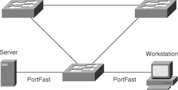
Spanning Tree PortFast causes an interface configured as a Layer 2 access port to enter the forwarding state immediately, bypassing the listening and learning states. Enable PortFast on Layer 2 access ports connected to a single workstation or server to allow those devices to connect to the network immediately, rather than waiting for spanning tree to converge. In Figure 6-1, a server and workstation are attached to an access switch through ports that have the PortFast feature enabled.
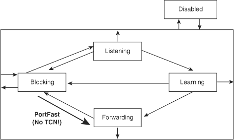
Figure 6-2 illustrates the modification in the STP state machine for interfaces configured for the PortFast feature. As illustrated in the figure, the STP state jumps directly from blocking to forwarding without going through the listening and learning state. In addition, PortFast suppresses topology change notifications.
Note
The purpose of PortFast is to minimize the time that access ports wait for STP to converge. The advantage of enabling PortFast is to prevent DHCP timeouts, Novell login problems, and AppleTalk address discovery problems on workstation bootup. Use this feature solely on access ports except in specific network designs. When enabling PortFast on a port connecting to another switch, there is a risk of creating a bridging loop.
On Cisco IOS–based Catalyst switches, use the following interface command to enable or disable the PortFast feature:
[no] spanning-tree portfast
Example 6-1 illustrates a user configuring the PortFast feature and verifying the configuration.
Example 6-1. Configuration and Verification of PortFast on Cisco IOS–Based Catalyst Switches
Switch#configure terminal
Enter configuration commands, one per line.  End with CNTL/Z.
Switch(config)#interface FastEthernet 3/27
Switch(config-if)#spanning-tree portfast
%Warning: portfast should only be enabled on ports connected to a single
 host. Connecting hubs, concentrators, switches, bridges, etc... to this
 interface  when portfast is enabled, can cause temporary bridging loops.
 Use with CAUTION

%Portfast has been configured on FastEthernet3/27 but will only
 have effect when the interface is in a non-trunking mode.
Switch(config-if)#end
Switch#
Switch#show spanning-tree interface FastEthernet 3/27 portfast
VLAN0001         enabled
On switches in the Building Access submodule, enable PortFast globally so that there is no need to explicitly enable PortFast on each port individually. Remember to explicitly disable PortFast on uplink ports that connect to distribution layer switches.
Use the following command to enable PortFast globally in global configuration mode:
spanning-tree portfast defaultNote
BPDU Guard puts the port in err-disable state if a PortFast-enabled port receives a BPDU. Err-disable port state, effectively the same as disable state, prevents any data ingress or egress from a port until the err-disabled configurable timeout period elapses or manual intervention occurs. A Catalyst switch uses the err-disable state to disable ports automatically in the case of other anomalous events or invalid configurations besides spanning tree. Enable the BPDU Guard feature on all ports configured for PortFast to prevent a network outage due to an accidental connection of a switching device on PortFast-enabled ports.
PortFast is a highly recommended configuration on end-user ports and server ports along with disabling negotiation of channeling and trunking. The end-result of these configurations is to allow immediate forwarding frames on link up. On Cisco IOS-based Catalyst switches, use the following command to place an interface into this desired configuration:
switchport mode hostExample 6-2 shows a user configuring an interface for connecting to a host.
Example 6-2. Configuration of Host Interface on Cisco IOS–Based Catalyst Switch
SwitchB#configure terminal
Enter configuration commands, one per line.  End with CNTL/Z.
SwitchB(config)#interface fastEthernet 3/9
SwitchB(config-if)#switchport host
switchport mode will be set to access
spanning-tree portfast will be enabled
channel group will be disabled
SwitchB(config-if)#end
SwitchB#
UplinkFast provides fast convergence after a direct link failure if one or more redundant Layer 2 links exist. UplinkFast defines interfaces in an uplink group on a per-VLAN basis; only one interface is forwarding at any given time. Specifically, an uplink group consists of the root port (which is forwarding) and a set of blocked ports. Typically, only a single blocking interface exists, but there is no limit to the number of blocking or alternate links. The uplink group provides an alternate path in case the currently forwarding link fails.
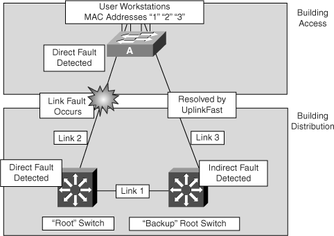
Figure 6-3 shows an example of a topology with switch A deployed in the Building Access submodule with uplink connections to the root switch over link 2 and the backup root switch over link 3 (both of these switches are in the Building Distribution submodule.) Initially, the port on switch A connected to link 2 is in the forwarding state, and the port connected to link 3 is in the blocking state.
As shown in Figure 6-3, when switch A detects a link failure on the currently active link 2 on the root port (a direct link failure), UplinkFast unblocks the blocked port on switch A and transitions it to the forwarding state without going through the listening and learning states. This switchover occurs within 5 seconds.
Note
UplinkFast is most useful in the Building Access submodule with at least one blocked port. This feature might not be useful for other types of applications.
Use the following global configuration command to enable UplinkFast:
spanning-tree uplinkfast [max-update-rate max-update-rate]
The max_update_rate value represents the number of multicast packets transmitted per second; the default is 150 packets per second (pps). The purpose of the multicast packets is explained later in this section.
Note
When you enable UplinkFast, it affects all VLANs on the switch. Catalyst switches do not support configuring UplinkFast on a per-VLAN basis.
Example 6-3 illustrates configuring UplinkFast on a Cisco IOS–based Catalyst switch.
UplinkFast increases the bridge priority to 49,152 and adds 3000 to the spanning-tree port cost of all interfaces on the switch, making it unlikely that the respective switch becomes a root switch. Catalyst switches do not support enabling UplinkFast for VLANs configured for a bridge priority. To enable UplinkFast on a VLAN with bridge priority configured, restore the bridge priority on the VLAN to the default value by entering the no spanning-tree vlan vlan-id priority command in global configuration mode.
To enhance the scalability of STP, UplinkFast also quenches the Topology Change Notification (TCN) messages that are normally transmitted toward the root bridge. Instead, the switch sends dummy multicast frames that proxy the MAC addresses of connected devices toward the root so that the upstream switch moves the MAC address table entries from the failed link to the new port immediately. This simple but effective mechanism updates the forwarding entries for the failed path without affecting other entries.
For more information on the operation of UplinkFast, refer to the following document on Cisco.com:
Document ID: 10575 Understanding and Configuring the Cisco UplinkFast Feature
UplinkFast is most useful in wiring-closet switches with a limited number of active VLANs. This feature might not be useful for other types of applications and should not be enabled on backbone or distribution layer switches.
Example 6-4 illustrates a user verifying the configuration of UplinkFast.
Example 6-4. Displaying UplinkFast Information
Switch#show spanning-tree uplinkfast
UplinkFast is enabled
Station update rate set to 400 packets/sec.
UplinkFast statistics
-----------------------
Number of transitions via uplinkFast (all VLANs)            :14
Number of proxy multicast addresses transmitted (all VLANs) :5308
Name                 Interface List
-------------------- ------------------------------------
VLAN1                Fa6/9(fwd), Gi5/7
VLAN2                Gi5/7(fwd)
VLAN3                Gi5/7(fwd)
BackboneFast is a complementary feature to UplinkFast. Whereas UplinkFast quickly responds to failures on links directly connected to distribution switches, it does not help with indirect failures in the backbone core. BackboneFast reduces the default convergence time in situations where the root port is lost and the backup link leads through a different switch. The convergence is reduced to 30 seconds from the default 50 seconds in such scenarios. However, BackboneFast does not eliminate the forward delay time and does not support direct link failures.
Note
When configuring BackboneFast, enable it on every switch on the network. Some older Cisco Catalyst switch models may not support the BackboneFast feature.
When a switch receives a BPDU from a designated switch that identifies the root bridge and the designated bridge as the same switch, the switch considers the BPDU an inferior BPDU. When a switch receives an inferior BPDU, it indicates that a link to which the switch is not directly connected (an indirect link) has failed; that is, the designated switch has lost its connection to the root switch.
The designated switch transmits the BPDUs with the information that it is now the root switch and the designated switch. The receiving switch ignores the inferior BPDU for the time defined by the max age setting.
After receiving inferior BPDUs, the receiving switch tries to determine whether there is an alternate path to the root switch:
If the port that received the inferior BPDUs is already in blocking mode, then the root port and other blocked ports on the switch become alternate paths to the root switch.
If the switch receives inferior BPDUs on a root port (when another switch has been introduced to the topology), then all presently blocking ports become alternate paths to the root switch. In addition, if the switch receives inferior BPDUs on a root port and there are no other blocking ports on the switch, the receiving switch assumes that the link to the root switch is down. After the time interval defined by the max age setting expires, the switch starts the root switch election process by declaring itself as the root.
If the switch that receives the inferior BPDU has alternate paths to the root switch, it uses those alternate paths to send a root link query (RLQ) BPDU. The objective of the RLQ BPDU is to determine whether the current root switch is still alive. The RLQ BPDU propagates toward the root switch through the intermediate switches, and eventually the root switch responds. If the responding root switch is the same as the original root switch, the switch detecting the indirect link failure assumes that the root switch is still alive. The switch immediately skips to the listening state for the port receiving the inferior BPDU. This process enables faster convergence in the event of a backbone link failure.
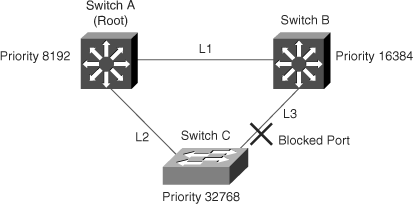
Figure 6-4 shows an example of a topology with no link failures. Switch A, the root switch, connects directly to switch B over link L1 and to switch C over link L2. In this example, because switch B has a lower priority than switch A but a higher priority than switch C, switch B becomes the designated bridge for link 3. Consequently, the Layer 2 interface on switch C that connects directly to switch B is in the blocking state.
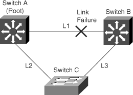
Next, assume that link L1 fails as shown in Figure 6-5. Switch A and switch B, the switches directly connected to this segment, instantly detect that the link is down. The blocking interface on switch C enters the forwarding state for the network to recover by itself. However, because link L1 does not directly connect to switch C, switch C does not start sending BPDUs on link L3 under the normal rules of STP until the time defined by the max age setting has expired.
In an STP environment without BackboneFast, when link L1 fails, switch C cannot detect the failure because it does not directly connect to link L1. Because switch B directly connects to the root switch over link L1, switch B detects the failure and elects itself the root. Then, switch B begins sending configuration BPDUs to switch C, listing itself as the root.
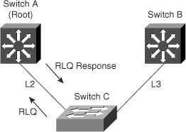
The following steps detail actions taken by Catalyst switches with BackboneFast enabled, as shown in Figure 6-6:
When switch C receives the inferior BPDU from switch B, switch C infers that an indirect failure has occurred.
Switch C sends out an RLQ.
Switch A receives the RLQ. Because switch A is the root bridge, it replies with an RLQ response, listing itself as the root bridge.
When switch C receives the RLQ response on its existing root port, it knows that it still has a stable connection to the root switch. Because switch C originated the RLQ request, it does not need to forward the RLQ response to other switches.
BackboneFast enables the blocked port on switch C to move immediately to the listening state without waiting for the time defined by the port’s max age setting to expire.
BackboneFast transitions the Layer 2 interface on switch C to the forwarding state, providing a path from switch B to switch A.
In this example, switch B can recover 20 seconds faster with BackboneFast enabled on the switches than without BackboneFast enabled. The total time for the switchover is approximately 30 seconds, twice the forward delay time (using the default forward delay time of 15 seconds).
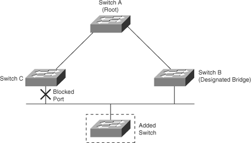
Figure 6-7 shows a new switch introduced into a shared-medium topology. BackboneFast does not affect this situation because the inferior BPDUs did not come from the recognized designated bridge (switch B). The new switch begins sending inferior BPDUs that indicate the new bridge is the root switch. However, the other switches ignore these inferior BPDUs, and the new switch learns that switch B is the designated bridge to switch A (root switch). The new switch learns the path to the root bridge by using the normal STP processes.
On Cisco IOS–based Catalyst switches, use the following global configuration command to enable or disable BackboneFast:
[no] spanning-tree backbonefast
For BackboneFast to function correctly, enable the feature on all switches in the network. Catalyst switches support BackboneFast for use with third-party switches.
Example 6-5 shows the configuration and verification of BackboneFast.
Example 6-5. Configuring and Verifying BackboneFast on Cisco IOS–Based Catalyst Switches
Switch#configure terminal
Enter configuration commands, one per line. End with CNTL/Z.
Switch(config)#spanning-tree backbonefast
Switch(config)#end
Switch#show spanning-tree backbonefast
BackboneFast is enabled

BackboneFast statistics
-----------------------
Number of transition via backboneFast (all VLANs) : 0
Number of inferior BPDUs received (all VLANs)     : 0
Number of RLQ request PDUs received (all VLANs)   : 0
Number of RLQ response PDUs received (all VLANs)  : 0
Number of RLQ request PDUs sent (all VLANs)       : 0
Number of RLQ response PDUs sent (all VLANs)      : 0
STP does not provide for checks and balances to ensure high availability in multilayer switched networks. As a result, Cisco introduced features such as the following to help fine-tune and increase resiliency of STP:
BPDU Guard—. Prevents accidental connection of switching devices to PortFast-enabled ports. Connecting switches to PortFast-enabled ports may cause Layer 2 loops or topology changes.
BPDU filtering—. Restricts the switch from sending unnecessary BPDUs out access ports.
Root Guard—. Prevents switches on access ports from becoming the root switch.
BPDU Guard puts an interface configured for STP PortFast in the err-disable state upon receipt of a BPDU. The BPDU Guard disables interfaces as a preventive step to avoid a potential bridging loop.
The STP BPDU Guard shuts down PortFast-configured interfaces that receive BPDUs, rather than putting them into the STP blocking state (the default behavior). In a valid configuration, PortFast-configured interfaces should not receive BPDUs. Reception of a BPDU by a PortFast-configured interface signals an invalid configuration, such as connection of an unauthorized device. BPDU Guard provides a secure response to invalid configurations, because the administrator must manually re-enable the err-disabled interface after fixing the invalid configuration. It is also possible to set up a time-out interval after which the switch automatically tries to re-enable the interface. However, if the invalid configuration still exists, the switch err-disables the interface again.
Note
STP applies the BPDU Guard feature globally to all PortFast-configured interfaces but can also be enabled/disabled per-interface basis.
To enable BPDU Guard or to disable BPDU Guard on a Cisco IOS–based Catalyst switch, use the following global configuration command:
[no] spanning-tree portfast bpduguard
Example 6-6 illustrates a user configuring and verifying the spanning-tree PortFast BPDU Guard feature.
Example 6-6. Configuring and Verifying BPDU Guard on Cisco IOS–Based Catalyst Switches
Switch#configure terminal
Enter configuration commands, one per line.  End with CNTL/Z.
Switch(config)# spanning-tree portfast bpduguard
Switch(config)# end
Switch#show spanning-tree summary totals

Root bridge for: none.
PortFast BPDU Guard is enabled
Etherchannel misconfiguration guard is enabled
UplinkFast is disabled
BackboneFast is disabled
Default pathcost method used is short

Name                 Blocking Listening Learning Forwarding STP Active
-------------------- -------- --------- -------- ---------- ---------
            34 VLANs 0        0         0        36         36
BPDU filtering supports the ability to prevent Catalyst switches from sending BPDUs on PortFast-enabled interfaces. Ports configured for the PortFast feature typically connect to host devices. Hosts do not participate in STP and hence drop the received BPDUs. As a result, BPDU filtering prevents unnecessary BPDUs from being transmitted to host devices.
Catalyst switches support configuring BPDU filtering on a per-port or global basis. If explicitly configured on an interface, the switch does not send BPDUs and drops all BPDUs it receives.
If globally enabled, the switch changes the interface back to normal STP operation if the port receives BPDUs on the respective interface. For example, if a PortFast-enabled interface receives a BPDU, it immediately loses its PortFast status with BPDU filtering enabled. In this case, the switch disables PortFast BPDU filtering on the respective interface, and STP resumes sending BPDUs from the port toward the connected device.
Caution
Configuration of BPDU filtering on a port connected to another switch may result in a bridging loop; use caution when deploying BPDU filtering. BPDU filtering is not a recommended configuration.
Table 6-1 lists all the possible PortFast BPDU filtering combinations.
Table 6-1. PortFast BPDU Filtering Port Configurations
Per-Port Configuration | Global Configuration | PortFast State | PortFast BPDU Filtering State |
|---|---|---|---|
Default | Enable | Enable | Enable |
Default | Enable | Disable | Disable |
Default | Disable | Not applicable | Disable |
Disable | Not applicable | Not applicable | Disable |
Enable | Not applicable | Not applicable | Enable |
If you enable BPDU Guard on the same interface as BPDU filtering, BPDU Guard has no effect, because BPDU filtering takes precedence over BPDU Guard.
To enable PortFast BPDU filtering globally on the switch, use the following command on Cisco IOS–based Catalyst switches:
spanning-tree portfast bpdufilter defaultTo verify the configuration, use the following command on Cisco IOS–based Catalyst switches:
show spanning-tree summary totalsRoot Guard is useful in avoiding Layer 2 loops during network anomalies. The Root Guard feature forces an interface to become a designated port, to prevent surrounding switches from becoming a root switch. In other words, Root Guard provides a way to enforce the root bridge placement in the network. Catalyst switches force Root Guard–enabled ports to be designated ports. If the bridge receives superior STP BPDUs on a Root Guard–enabled port, the port moves to a root-inconsistent STP state (effectively equal to a listening state), and the switch does not forward traffic out of that port. As a result, this feature effectively enforces the position of the root bridge.
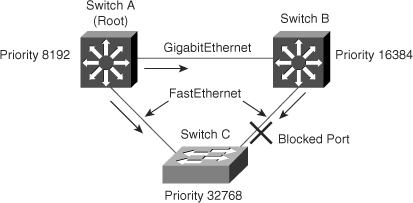
Figure 6-8 shows a sample topology to illustrate the Root Guard feature. Switches A and B comprise the core of the network, and switch A is the root bridge for a VLAN. Switch C is an access layer switch. The link between switch B and switch C is blocking on the switch C side. Figure 6-8 shows the flow of STP BPDUs with arrows.
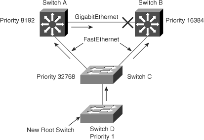
In Figure 6-9, when switch D is connected to switch C, it begins to participate in STP. If the priority of switch D is 0 or any value lower than that of the current root bridge, switch D becomes the root bridge for that VLAN based on normal STP guidelines. In this specific scenario, however, having switch D as the root causes the Gigabit Ethernet link that is connecting the two core switches to block, thus causing all the data in that particular VLAN to flow via a 100-Mbps link across the access layer. If there is more data flowing between the core switches in that VLAN than this link may accommodate, packet loss can occur, causing performance issues or network connectivity problems. An even worse scenario may occur if switch D is unstable and causes frequent reconvergence of the root bridge.
The Root Guard feature can protect against such issues. After the Root Guard feature is enabled on a port, the switch does not allow that port to become an STP root port. The port remains as an STP-designated port. In addition, if a better BPDU is received on the port, Root Guard disables (err-disables) the port rather than processing the BPDU. If an unauthorized device starts sending BPDUs with a better bridge ID, the normal STP process would elect the new switch as the root switch. By disabling the port, the network topology is protected.
The current design recommendation is to enable Root Guard on all access ports so that a root bridge is not established through these ports. In Figure 6-9, enable Root Guard on switches A, B, and C on the following ports:
Switch A (Distribution/Core): Any access port
Switch B (Distribution/Core): Any access port
Switch C (Access): Any access port including the port connecting to switch D
In this configuration, switch C blocks the port connecting to switch D when it receives a better (superior) BPDU. The port transitions to a special STP state (root-inconsistent), which is effectively the same as the listening state. No traffic passes through the port in root-inconsistent state.
When switch D stops sending superior BPDUs, the port unblocks again and goes through regular STP transition of listening, learning, and eventually to the forwarding state. Recovery is automatic; no intervention is required.
In addition, Catalyst switches log the following message when a Root Guard–enabled port receives a superior BPDU:
%SPANTREE-2-ROOTGUARDBLOCK: Port 1/1 tried to become non-designated in VLAN 77.
    Moved to root-inconsistent state
To enable Root Guard on a Layer 2 access port to force it to become a designated port, or to disable Root Guard, use the following interface-level command on Cisco IOS–based Catalyst switches:
[no] spanning-tree guard root
Example 6-7 illustrates a user enabling the Root Guard feature on FastEthernet interface 5/8 and verifying the configuration.
Example 6-7. Configuring and Verifying Root Guard on Cisco IOS–Based Catalyst Switches
Switch#configure terminal
Enter configuration commands, one per line.  End with CNTL/Z.
Switch(config)#interface FastEthernet 5/8
Switch(config-if)#spanning-tree guard root
Switch(config-if)#end
Switch#show running-config interface FastEthernet 5/8
Building configuration...
Current configuration: 67 bytes
!
interface FastEthernet5/8
switchport mode access
spanning-tree guard root
end
!
Example 6-8 shows how to determine whether any interfaces are in root-inconsistent state.
Example 6-8. Displaying Root-Inconsistent Interfaces on Cisco IOS–Based Catalyst Switches
Switch#show spanning-tree inconsistentports
Name                 Interface              Inconsistency
-------------------- ---------------------- ------------------
VLAN0001             FastEthernet3/1        Port Type Inconsistent
VLAN0001             FastEthernet3/2        Port Type Inconsistent
VLAN1002             FastEthernet3/1        Port Type Inconsistent
VLAN1002             FastEthernet3/2        Port Type Inconsistent
Number of inconsistent ports (segments) in the system :4Prevention of forwarding loops and black holes in a network is a required aspect of network design. Cisco Catalyst switches support two important features to address such conditions:
Aggressive mode UDLD—. Aggressive mode UDLD detects and disables unidirectional links. UDLD is explained in detail in Chapter 7, “Enhancing Network Stability, Functionality, Reliability, and Performance Using Advanced Features.”
Loop Guard—. The Loop Guard STP feature improves the stability of Layer 2 networks by preventing bridging loops. The following section discusses Loop Guard.
Loop Guard provides additional protection against Layer 2 forwarding loops (STP loops). A bridging loop happens when an STP blocking port in a redundant topology erroneously transitions to the forwarding state. This usually occurs because one of the ports of a physically redundant topology (not necessarily the STP blocking port) has stopped receiving STP BPDUs. In STP, switches rely on continuous reception or transmission of BPDUs, depending on the port role. (A designated port transmits BPDUs, whereas a nondesignated port receives BPDUs.)
When one of the ports in a physically redundant topology stops receiving BPDUs, STP conceives the topology as loop-free. Eventually, the blocking port from the alternate or backup port transitions to a designated port and then moves to the STP forwarding state, creating a bridging loop.
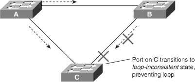
With the Loop Guard feature, switches do an additional check before transitioning to the STP forwarding state. If switches stop receiving BPDUs on a nondesignated port with the Loop Guard feature enabled, the switch places the port into the STP loop-inconsistent blocking state instead of moving through the listening, learning, and forwarding states.
When the Loop Guard feature places a port into the loop-inconsistent blocking state, the switch logs the following message:
SPANTREE-2-LOOPGUARDBLOCK: No BPDUs were received on port 3/2 in vlan 3.
    Moved to loop-inconsistent state.
If a switch receives a BPDU on a port in the loop-inconsistent STP state, the port transitions through STP states according to the received BPDU. As a result, recovery is automatic, and no manual intervention is necessary. After the recovery, the switch logs the following message:
SPANTREE-2-LOOPGUARDUNBLOCK: port 3/2 restored in vlan 3.
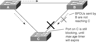
To illustrate Loop Guard behavior, consider the example in Figure 6-10. Switch A is the root switch. Due to unidirectional link failure on the link between switch B and switch C, switch C is not receiving BPDUs from B.
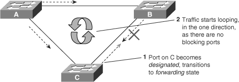
Without Loop Guard, the STP blocking port on switch C transitions to the STP listening state after the max age timer expires, and ultimately to the forwarding state after two times the forward delay time. When the port moves into the forwarding state, a bridging loop occurs, as shown in Figure 6-11.
With the Loop Guard feature enabled, the blocking port on switch C transitions into the STP loop-inconsistent state when the max age timer expires, as shown in Figure 6-12. A port in the STP loop-inconsistent state does not pass data traffic; hence, a bridging loop does not occur. The loop-inconsistent state is effectively equal to the blocking state.
You configure the Loop Guard feature on a per-port basis, although the feature blocks inconsistent ports on a per-VLAN basis. For example, on a trunk port, if BPDUs are not received for only one particular VLAN, the switch blocks only that VLAN (that is, moves the port for that VLAN to the loop-inconsistent STP state). In the case of an EtherChannel interface, the channel status goes into the inconsistent state for all the ports belonging to the channel group for the particular VLAN not receiving BPDUs. (Recall that Catalyst switches consider EtherChannel as one logical port from the STP point of view.)
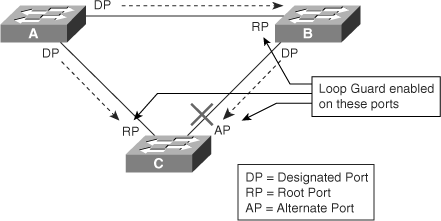
Enable the Loop Guard feature on all nondesignated ports, and not just for blocking ports. More precisely, Loop Guard should be enabled on root and alternate ports for all possible combinations of active topologies. Before enabling Loop Guard, however, consider all possible failover scenarios. Figure 6-13 shows a sample scenario and indicates the ports configured for Loop Guard.
Loop Guard is disabled by default on Catalyst switches. Use the following interface-level configuration command to enable Loop Guard on Cisco IOS–based Catalyst switches:
spanning-tree guard loopNote
Loop Guard and Root Guard cannot coexist on the same port. As a result, enabling Loop Guard disables any previous configuration of Root Guard on a per-port basis.
When you enable Loop Guard globally for application to all ports, the switch enables Loop Guard only on ports considered to be point-to-point links. Catalyst switches consider full-duplex ports as point-to-point links. It is still possible to configure, or override, the global configuration of Loop Guard on a per-port basis.
To enable Loop Guard globally on Cisco IOS–based Catalyst switches, use the following global configuration command:
spanning-tree loopguard defaultTo disable Loop Guard on any specific interface on Cisco IOS–based Catalyst switches, issue the following interface configuration command:
no spanning-tree guardTo verify the Loop Guard status on an interface, issue the following EXEC command on Cisco IOS–based Catalyst switches:
show spanning-tree interface interface-id detail
Example 6-9 illustrates a user verifying the status of Loop Guard on interface FastEthernet 3/42.
Example 6-9. Verifying the Status of Loop Guard on an Interface on Cisco IOS–Based Catalyst Switches
Switch#show spanning-tree interface FastEthernet 3/42 detail
 Port 170 (FastEthernet3/42) of VLAN0001 is blocking
   Port path cost 19, Port priority 128, Port Identifier 128.170.
   Designated root has priority 8193, address 0009.e845.6480
   Designated bridge has priority 8193, address 0009.e845.6480
   Designated port id is 128.160, designated path cost 0
   Timers: message age 1, forward delay 0, hold 0
   Number of transitions to forwarding state: 0
   Link type is point-to-point by default
   Loop guard is enabled on the port
BPDU: sent 1, received 4501Loop Guard and aggressive mode UDLD functionality overlap insofar as both protect against STP failures caused by unidirectional links. These two features are different, however, in their approach to the problem and in functionality. Table 6-2 compares and contrasts the Loop Guard and aggressive mode UDLD features.
Table 6-2. Comparison Between Loop Guard and Aggressive Mode UDLD
Loop Guard | Aggressive Mode UDLD | |
|---|---|---|
Configuration | Per port | Per port |
Action granularity | Per VLAN | Per port |
Auto-recovery | Yes | Yes, with err-disable timeout feature |
Protection against STP failures caused by unidirectional links | Yes, when enabled on all root ports and alternate ports in redundant topology | Yes, when enabled on all links in redundant topology |
Protection against STP failures caused by problem in software resulting in designated switch not sending BPDUs | Yes | No |
Protection against incorrect wiring | No | Yes |
The most noticeable difference between aggressive mode UDLD and Loop Guard is in regard to STP. Aggressive mode UDLD cannot detect failures caused by problems in software in the designated switch not sending the BPDU. Problems resulting from software failures are less common than failures caused by unidirectional links that result from hardware failures. Nevertheless, aggressive mode UDLD is more robust in its ability to detect unidirectional links on EtherChannel. Loop Guard blocks all interfaces of the EtherChannel in such a failure by putting the EtherChannel into the loop-inconsistent state for a VLAN or for all VLANs, while aggressive mode UDLD disables the single port that is exhibiting problems. In addition, aggressive mode UDLD is not dependent on STP, so it supports Layer 3 links as well.
In addition, Loop Guard does not support shared links or interfaces that are unidirectional on switch Bootup. If a port is unidirectional on switch Bootup, the port never receives BPDUs and becomes a designated port. Loop Guard does not support this scenario, because the behavior is not distinguishable from normal STP operation. Aggressive mode UDLD does provide protection against such a failure scenario.
Enabling both aggressive mode UDLD and Loop Guard provides the highest level of protection against bridging loops and black holes in multilayer switched networks.
Bridging loops generally characterize STP problems. Troubleshooting STP involves identifying and preventing such loops.
The primary function of STP is to prevent loops created by redundant links in bridged networks. STP operates at Layer 2 of the OSI model. STP fails in specific cases, such as hardware or software anomalies. Troubleshooting these situations is typically very difficult, depending on the design of the network.
The following subsections highlight common network conditions that lead to STP problems, listed as follows:
Duplex mismatch on point-to-point links is a common configuration error. Duplex mismatch occurs specifically when one side of the link is manually configured as full duplex and the other side is using the default configuration for auto-negotiation. Such a configuration leads to duplex mismatch.
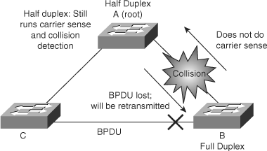
The worst-case scenario for a duplex mismatch is when a bridge that is sending BPDUs is configured for half duplex on a link while its peer is configured for full duplex. In Figure 6-14, the duplex mismatch on the link between switch A and switch B could potentially lead to a bridging loop. Because switch B is configured for full duplex, it starts forwarding frames even if switch A is already using the link. This is a problem for switch A, which detects a collision and runs the back-off algorithm before attempting another transmission of its frame. If there is enough traffic from switch B to switch A, every packet (including the BPDUs) sent by switch A is deferred or has a collision and is subsequently dropped. From an STP point of view, because switch B no longer receives BPDUs from switch A, it assumes the root bridge is no longer present. Consequently, switch B moves its port to switch C into the forwarding state, creating a Layer 2 loop.
A unidirectional link is a frequent cause for a bridging loop. An undetected failure on a fiber link or a problem with a transceiver usually causes unidirectional links. With STP enabled to provide redundancy, any condition that results in a link maintaining a physical link connected status on both link partners but operating in a one-way communication state is detrimental to network stability because it could lead to bridging loops and routing black holes. Figure 6-15 shows such an example of a unidirectional link failure affecting STP.
The link between switch A and switch B is unidirectional and drops traffic from switch A to switch B while transmitting traffic from switch B to switch A. Suppose, however, that the interface on switch B should be blocking. An interface blocks only if it receives BPDUs from a bridge that has a better priority. In this case, all the BPDUs coming from switch A are lost, and switch B eventually moves to the forwarding state, creating a loop. Note that in this case, if the failure exists at startup, STP does not converge correctly. In addition, rebooting of the bridges has absolutely no effect on this scenario.
To resolve this problem, Cisco introduced the UDLD and A-UDLD features on current-generation switches. These features can detect incorrect cabling or unidirectional links and automatically put the affected port in err-disable state. The recommended practice is to use A-UDLD on all point-to-point interfaces in any multilayer switched network. See Chapter 7 for more details about UDLD and A-UDLD.
Frame corruption is another cause for STP failure. If an interface is experiencing a high rate of physical errors, the result may be lost BPDUs, which may lead to an interface in the blocking state moving to the forwarding state. However, this case is rare, because STP default parameters are conservative. The blocking port needs to miss consecutive BPDUs for 50 seconds before transitioning to the forwarding state. In addition, any single BPDU that is successfully received by the switch breaks the loop. This case is more common for nondefault STP parameters and aggressive STP timer values. Frame corruption is generally a result of a duplex mismatch, bad cable, or incorrect cable length.
Even on high-end switches that perform most of their switching functions in hardware with specialized application-specific integrated circuits (ASIC), STP is performed by the CPU (software-based). This means that if the CPU of the bridge is over utilized for any reason, it may lack the resources to send out BPDUs. STP is generally not a processor-intensive application and has priority over other processes; therefore, a resource problem is unlikely to arise. However, you need to exercise caution when multiple VLANs in PVST+ mode exist. Consult the product documentation for the recommended number of VLANs and STP instances on any specific Catalyst switch to avoid exhausting resources.
As discussed in the section titled “PortFast” earlier in this chapter, the PortFast feature, when enabled on a port, bypasses the listening and learning states of STP, and the port transitions to the forwarding mode on linkup. The fast transition may lead to bridging loops if configured on incorrect ports.
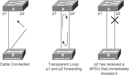
In Figure 6-16, switch A has port p1 in the forwarding state and port p2 configured for PortFast. Device B is a hub. Port p2 goes to forwarding and creates a loop between p1 and p2 as soon as the second cable plugs into switch A. The loop ceases as soon as p1 or p2 receives a BPDU that transitions one of these two ports into blocking mode. The problem with this type of transient loop condition is that if the looping traffic is intensive, the bridge may have trouble successfully sending the BPDU that stops the loop. The BPDU Guard prevents this type of event from occurring.
A short timer value for the max age or the forward delay timers may lead to an unstable STP topology. The loss of BPDUs due to short timers may cause a momentary STP loop, and thus any tuning of the parameters should be done with caution. Another potential problem with short timer values relates to the diameter of the bridged network. The default max age timer for STP indicates a maximum network diameter of seven devices. As a result, two distinct bridges in the network should not be more than seven bridges away from one another. Part of this restriction comes from the age field carried by BPDUs: When a BPDU propagates from the root bridge toward the leaves of the tree, the age field gets incremented each time it goes though a bridge. Eventually, when the age field of a BPDU goes beyond max age, the bridge discards the BPDU. Typically, this discarding of the BPDU occurs only if the root is too far away from some bridges of the network. Hence, having a large STP diameter affects the convergence time.
Troubleshooting STP problems can be difficult if logical troubleshooting procedures are not deployed in advance. Occasionally, rebooting of the switches may resolve the problem temporarily, but without determining the underlying cause of the problem, the problem is likely to return.
The following steps provide a general overview of a methodology for troubleshooting STP:
Know the network.
Identify a bridging loop.
Restore connectivity.
Check the port status.
Check for resource errors.
Disable unneeded features.
The following subsections explain troubleshooting Layer 2 bridging loops in more detail.
Before you troubleshoot a bridging loop, you must understand the following basic characteristics of your network:
The topology of the bridged network
The location of the root bridge
The location of the blocked ports and, therefore, the redundant links
Knowing the basic characteristics is essential in troubleshooting any Layer 2 issue. In addition, knowledge of the network helps to focus attention on the critical ports on key devices, because most of the STP troubleshooting steps simply involve using show commands to identify error conditions.
The best way to identify a bridging loop is to capture the traffic on a saturated link and to determine whether duplicate packets are propagating. If all users in a specific bridging domain have connectivity issues at the same time, a bridging loop is a possible cause. Check the port utilization on devices and look for abnormal values. In addition, you may see other protocols break down due to the bridging loops. For example, HSRP may complain of duplicate IP addresses if a loop causes it to see its own packets. Another common message during a loop is constant flapping of MAC addresses between interfaces. In a stable network, MAC addresses do not flap. In addition, be careful not to associate a bridging loop with a packet storm caused by another anomalous event such as an Internet worm or virus.
Bridging loops have severe consequences on a bridged network. Administrators generally do not have time to look for the cause of a loop, however, preferring to restore connectivity as soon as possible and identify potential issues later. Restoring connectivity consists of the following two actions:
Breaking the loop—. A simple solution is to manually disable every port that is providing redundancy in the network. Identify the part of the network that is more affected and start disabling ports in that area. If possible, start by disabling ports that should be in the blocking state. Check to see whether network connectivity is restored while disabling one port at a time.
Logging events—. If it is not possible to identify the source of the problem or if the problem is transient, enable logging and increase the logging level of STP events on the switches experiencing the failure. At a minimum, enable logging on switches with blocked ports, because the transition of a blocked port to forwarding state creates the loop.
To log detailed events or to identify STP problems, use debug commands on Cisco IOS–based Catalyst switches. Debugging commands, if used with care, may help to identify the source of the problem.
Use the following command to enable STP debugging:
debug spanning-tree eventsWarning
As with all debug commands, be careful with debug spanning-tree, because it is extremely resource intensive.
Example 6-10 shows sample debug output for spanning-tree events.
Example 6-10. Spanning-Tree Events Debug on Cisco IOS–Based Catalyst Switches
Switch#debug spanning-tree events
Spanning Tree event debugging is on
Switch#
*Mar  5 21:23:14.994: STP: VLAN0013 sent Topology Change Notice on Gi0/3
*Mar  5 21:23:14.994: STP: VLAN0014 sent Topology Change Notice on Gi0/4
*Mar  5 21:23:14.994: STP: VLAN0051 sent Topology Change Notice on Po3
*Mar  5 21:23:14.994: STP: VLAN0052 sent Topology Change Notice on Po4
*Mar  5 21:23:15.982: %LINEPROTO-5-UPDOWN: Line protocol on Interface
GigabitEthernet0/1, changed state to down
*Mar  5 21:23:16.958: STP: VLAN0001 Topology Change rcvd on Po1
Use the following command from global configuration mode to capture debug information into the logging buffer of a Catalyst switch (see Chapter 3, “Initial Configuration and Troubleshooting of Cisco Multilayer Switches,” for more details on system logging):
logging bufferedInvestigate the blocking ports first and then the other ports. The following are several guidelines for troubleshooting port status:
Blocked ports—. Check to make sure the switch reports receiving BPDUs periodically on root and blocked ports. Issue the following command on Cisco IOS–based Catalyst switches to display the number of BPDUs received on each interface:
show spanning-tree vlan vlan-id detail
Issue the command multiple times to determine whether the device is receiving BPDUs.
Duplex mismatch—. To look for a duplex mismatch, check on each side of a point-to-point link. Simply use the show interface command to check the speed and duplex status of the specified ports.
Port utilization—. An overloaded interface may fail to transmit vital BPDUs and is also an indication of a possible bridging loop. Use the show interface command to determine interface utilization using the load of the interface and packet input and output rates.
Frame corruption—. Look for increases in the input error fields of the show interface command.
High CPU utilization may lead to network instability for switches running STP. Use the show processes cpu command to check whether the CPU utilization is approaching 100 percent. Cisco Catalyst switches prioritize control packets such as BPDU over any lower-priority traffic; hence, the switch would be stable with higher CPU if it were just processing low-priority traffic.
Disabling as many features as possible reduces troubleshooting complexity. EtherChannel, for example, is a feature that bundles several different links into a single logical port. It may be helpful to disable this feature while troubleshooting. In general, simplifying the network configuration reduces the troubleshooting effort. If configuration changes are made during the troubleshooting effort, note the changes. An alternate way is to save the configuration by maintaining a copy of the configuring in bootflash or on a TFTP server. After the root cause is found and fixed, the removed configurations can be easily reapplied.
The following bullets review important BCMSN exam preparation points of this chapter. The bullets only briefly highlight the main points of this chapter related to the BCMSN exam. Consult the text of this chapter for additional information regarding these topics. Table 6-3 lists important commands to review for the BCMSN exam:
The STP PortFast feature enables host ports to transition to the forwarding state without the need to go through the listening and learning states. Therefore, this feature removes the STP delay, which enables a switch port to forward frames after link-up.
The STP BPDU Guard feature prevents network interruptions in situations where devices connected to PortFast-enabled ports accidentally or maliciously loop back traffic including BPDU to the network.
The BPDU filter feature prevents switches from sending BPDUs on host ports because hosts do not participate in STP and hence are unnecessary.
The Root Guard feature prevents switches connected to undesirable ports, such as host or edge ports, from becoming a root switch, thus preventing network disruption.
The Loop Guard feature prevents spanning-tree loops by preventing nondesignated ports from transitioning into the forwarding state when the port ceases to receive BPDUs. Aggressive mode UDLD provides additional loop prevention features and should be enabled on inter-switch links.
STP UplinkFast provides fast convergence after a direct link failure if one or more redundant Layer 2 links exist.
STP BackboneFast reduces the default convergence time in indirect link failure scenarios.
STP problems can be caused by issues such as duplex mismatches on interfaces connecting switches, unidirectional link failures, frame corruption, incorrect PortFast configuration, resource errors, incorrect tuning of STP parameters, software defects, or hardware failures.
Troubleshooting STP issues involves “knowing the network topology” ahead of time, knowing the backup and redundant connections, and being able to quickly remove redundancy.
Table 6-3. Commands to Review
Description | |
|---|---|
debug spanning-tree events | Enables debugging for STP related events on a switch |
show processes cpu | Displays the processor utilization information |
show spanning-tree backbonefast | Displays the STP BackboneFast status and statistics |
show spanning-tree uplinkfast | Displays the STP UplinkFast status and statistics |
(config-if)#spanning-tree guard loop | Configures the Loop Guard on the specified interface |
(config-if)#spanning-tree guard root | Configures the Root Guard feature on the specified interface |
(config-if)#spanning-tree portfast | Configures the PortFast feature on the specified interface |
(config)#spanning-tree portfast bpdufilter default | Configures the STP BPDU filter feature on all PortFast-enabled interfaces by default |
(config-if)#spanning-tree portfast bpduguard | Configures the BPDU Guard feature on a PortFast-enabled interface |
The Cisco STP enhancements provide robustness and resiliency to the protocol. These enhancements add availability to the multilayer switched network. These enhancements not only isolate bridging loops but also prevent bridging loops from occurring.
Complete this exercise to practice configuring BackboneFast, UplinkFast, Root Guard, and PortFast features discussed in this chapter.
The following resources and equipment are required to complete this exercise:
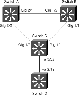
Catalyst switches, as shown in Figure 6-17
Terminal server connected to the console port of each laboratory device
PC connected to the terminal server to access the devices
The devices in the network should be connected and ready for use. In this configuration exercise, you will configure and verify some of the features reviewed in this chapter. After completing this exercise, you will be able to do the following:
Configure and verify BackboneFast
Configure and verify UplinkFast
Configure and verify Root Guard
Configure and verify PortFast
This exercise assumes that the switches are already configured as required in the configuration exercise found in Chapter 5.
Figure 6-17 shows the network layout for this configuration exercise, which extends upon the topology in Figure 5-34 in Chapter 5. Tasks 1 and 2 only require switches A, B, and C. Task 3 requires the introduction of switch D.
In this configuration exercise, you will use the commands listed in Table 6-4, which are listed in alphabetical order so that you can easily locate the information you need. Refer to this list if you need configuration command assistance during the configuration exercise.
Table 6-4. Command List for Configuration Exercise
Command | Description |
|---|---|
configure terminal | From privileged EXEC mode, enters global configuration mode |
end | Exits the configuration mode |
exit | Exits the current mode |
interface fastethernet | gigabitethernet slot/ port | Enters interface configuration mode for a Catalyst switch with a Fast Ethernet or Gigabit Ethernet interface installed |
show running-config interface interface-id | Displays running configuration of the specific interface |
show spanning-tree backbonefast | Displays STP BackboneFast status and statistics |
show spanning-tree interface interface-id portfast | Displays STP PortFast status for the specified interface |
show spanning-tree uplinkfast | Displays STP UplinkFast status and details |
spanning-tree backbonefast | Configures STP BackboneFast on the switch |
spanning-tree guard root | Configures STP Root Guard on an interface |
spanning-tree uplinkfast | Configures STP UplinkFast on the switch |
Configure BackboneFast on all three switches, A, B, C. Use the spanning-tree backbonefast command.
SwitchA#configure terminal
Enter configuration commands, one per line.  End with CNTL/Z.
SwitchA(config)#spanning-tree backbonefast
SwitchA(config)#end

SwitchB#configure terminal
Enter configuration commands, one per line.  End with CNTL/Z.
SwitchB(config)#spanning-tree backbonefast
SwitchB(config)#end

SwitchC#configure terminal
Enter configuration commands, one per line.  End with CNTL/Z.
SwitchC(config)#spanning-tree backbonefast
SwitchC(config)#end
Verify the BackboneFast configuration using the show spanning-tree backbonefast command.
SwitchA#show spanning-tree backbonefast
BackboneFast is enabled

BackboneFast statistics
-----------------------
Number of transition via backboneFast (all VLANs)         : 0
Number of inferior BPDUs received (all VLANs)             : 0
Number of RLQ request PDUs received (all VLANs)           : 0
Number of RLQ response PDUs received (all VLANs)          : 0
Number of RLQ request PDUs sent (all VLANs)               : 0
Number of RLQ response PDUs sent (all VLANs)              : 0
Switch B and switch C have similar output.
Configure UplinkFast on the access layer switch C. Use the spanning-tree uplinkfast command.
SwitchC#configure terminal
Enter configuration commands, one per line.  End with CNTL/Z.
SwitchC(config)#spanning-tree uplinkfast
SwitchC(config)#end
Verify the UplinkFast configuration using the show spanning-tree uplinkfast command.
SwitchC#show spanning-tree uplinkfast
UplinkFast is enabled

Station update rate set to 150 packets/sec.

UplinkFast statistics
-----------------------
Number of transitions via uplinkFast (all VLANs)            : 0
Number of proxy multicast addresses transmitted (all VLANs) : 0

Name                 Interface List
-------------------- ------------------------------------
VLAN0001             Gi1/2(fwd), Gi1/1
VLAN0002             Gi1/1(fwd), Gi1/2
As shown in Figure 6-17, a new switch, switch D, has been introduced into the topology. On Switch C, configure Root Guard on the interface connecting to switch D to prevent switch D from becoming the root switch. Use the spanning-tree guard root command.
SwitchC#configure terminal
Enter configuration commands, one per line.  End with CNTL/Z.
SwitchC(config)#interface fastEthernet 3/32
SwitchC(config-if)#spanning-tree guard root
SwitchC(config-if)#end
SwitchC#
Verify the Root Guard configuration using the show running-config interface interface-id command.
SwitchC#
SwitchC#show running-config interface fastEthernet 3/32
Building configuration...

Current configuration : 60 bytes
!
interface FastEthernet3/32
 spanning-tree guard root
end
Configure PortFast using the spanning-tree portfast command on switch C for the interface range FastEthernet 2/1–2/48, hypothetically where the workstations would be connected.
  SwitchC#configure terminal
Enter configuration commands, one per line.  End with CNTL/Z.
SwitchC(config)#interface range fastEthernet 2/1 - 2/48
SwitchC(config-if-range)#spanning-tree portfast
%Warning: portfast should only be enabled on ports connected to a single
 host. Connecting hubs, concentrators, switches, bridges, etc... to this
 interface  when portfast is enabled, can cause temporary bridging loops.
 Use with CAUTION

%Portfast will be configured in 48 interfaces due to the range command
 but will only have effect when the interfaces are in a non-trunking mode.
SwitchC(config-if-range)#end
SwitchC#
Verify the PortFast configuration using the show spanning-tree interface interface-id portfast command.
SwitchC#show show spanning-tree interface fastEthernet 3/32 portfast
VLAN0001         enabled
Complete this exercise to practice how to identify and resolve a Layer 2 loop in a small network scenario and display some commands essential to troubleshooting a real network STP loop, as discussed in this chapter. For details on potential reasons for a bridging loop, refer to the “Troubleshooting STP” section of this chapter.
The following resources and equipment are required to complete this exercise:
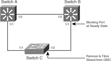
Catalyst switches, as shown in Figure 6-18
A terminal server connected to the console port of each laboratory device
A PC connected to the terminal server to access the devices
The devices in the network should be connected and ready for use. In this configuration exercise, you will locate and resolve a simulated failure leading to an STP loop. After completing this exercise, you will be able to do the following:
Identify an STP loop
Resolve an STP loop
Be familiar with commands essential to troubleshooting an STP loop
Figure 6-18 shows the network layout for this configuration exercise.
In this configuration exercise, you will use the commands listed in Table 6-5, which are listed in alphabetical order so that you can easily locate the information you need. Refer to this list if you need configuration command assistance during the configuration exercise.
Table 6-5. Command List for Configuration Exercise
Command | Description |
|---|---|
configure terminal | From privileged EXEC mode, enters global configuration mode |
end | Exits the configuration mode |
exit | Exits the current mode |
interface fastethernet | gigabitethernet slot/ port | Enters interface configuration mode for a Catalyst switch with a Fast Ethernet or Gigabit Ethernet interface installed |
show catalyst6000 traffic-meter | Displays the backplane utilization on a Catalyst 6500 switch |
show interface interface-id counters errors | Displays error counters for the specific interface |
show logging | Displays the syslog messages on a switch |
show processes cpu | Displays the processor utilization information |
show spanning-tree vlan vlan-id detail | Displays detailed spanning tree instance information for the specific VLAN on a switch |
show udld interface-id | Displays UDLD status and neighbor information for an interface |
shutdown | Disables the interface |
Layer 2 loops caused by an STP issue generally also cause network connectivity issues for network users and are usually associated with certain symptoms. These symptoms include packet loss, HSRP duplicate IP address error messages, total loss of connectivity, MAC-address flapping error messages, and various other syslog error messages. As a result, the first step in troubleshooting a perceived Layer 2 loop or STP issue is to check the syslogs of all the core and Building Distribution switches in the network. Best practice is to maintain a syslog server in addition to the logging buffer on the Catalyst switch. (See Chapter 3 for more details.) To display logs on Cisco switches, use the show logging command. As a first step in this exercise, display the logs on switches A and C to verify the error messages.
SwitchA#show logging
Syslog logging: enabled (0 messages dropped, 0 messages rate-limited, 0
flushes, 0 overruns)
    Console logging: level debugging, 40 messages logged
    Monitor logging: level debugging, 0 messages logged
    Buffer logging: level debugging, 50 messages logged
    Exception Logging: size (8192 bytes)
    Count and timestamp logging messages: disabled
    Trap logging: level informational, 51 message lines logged

Log Buffer (4096 bytes):

00:24:50: %STANDBY-3-DUPADDR: Duplicate address 10.10.0.1 on Vlan10,
sourced by 0000.0c07.ac01
00:24:50: %STANDBY-3-DUPADDR: Duplicate address 10.10.0.1 on Vlan10,
sourced by 0000.0c07.ac01
<output truncated>
SwitchC#show logging
Syslog logging: enabled (0 messages dropped, 0 messages rate-limited, 0
flushes, 0 overruns)
    Console logging: level debugging, 23 messages logged
    Monitor logging: level debugging, 0 messages logged
    Buffer logging: level debugging, 23 messages logged
    Exception Logging: size (8192 bytes)
    Count and timestamp logging messages: disabled
    Trap logging: level informational, 24 message lines logged

Log Buffer (4096 bytes):
00:24:20: %C4K_EBM-4-HOSTFLAPPING: Host 00:00:65:00:00:02 is flapping
between port 1/2 and port 1/1
00:24:35: %C4K_EBM-4-HOSTFLAPPING: Host 00:00:65:00:00:02 is flapping
between port 1/2 and port 1/1
As indicated in the logging buffer, switch C is logging host flapping error messages. Also, switch A is reporting duplicate HSRP IP address messages, a common error associated with Layer 2 loops. These are a strong indication of a Layer 2 loop or STP issue. In addition, the flapping error message indicates that the flapping is occurring between ports 1/1 and 1/2, which indicates where the loop might be occurring. However, further investigation is needed, including investigating switches and devices connected off port 1/2.
Another symptom of a Layer 2 loop or STP issue is high CPU utilization. BPDUs, broadcasts, and multicast frames are generally “punted” to the CPU (Layer 3 engine) for processing by the switch. Extreme abundance of BPDUs, broadcasts, or multicast frames that occur during a Layer 2 loop condition results in high CPU utilization conditions. As such, high CPU utilization conditions (over 75 percent) need investigation. To display the CPU utilization on Catalyst switches in Cisco IOS, use the show processes cpu command. In this step of the exercise, display the processor utilization on switch C to verify a symptom of the Layer 2 loop.
SwitchC#show processes cpu CPU utilization for five seconds: 75%/0%; one minute: 76%; five minutes: 76% PID Runtime(ms) Invoked uSecs 5Sec 1Min 5Min TTY Process 1 0 1 0 0.00% 0.00% 0.00% 0 Chunk Manager 2 28 248759 0 0.00%0.00%0.00%0 Load Meter 3 5620 469937 11 0.00% 0.00% 0.00% 0 Exec 4 0 1 0 0.00% 0.00% 0.00% 0 Deferred Events 5 848512 168176 5045 0.00% 0.04% 0.05% 0 Check heaps 6 0 2 0 0.00% 0.00% 0.00% 0 Pool Manager 7 0 2 0 0.00% 0.00% 0.00% 0 Timers 8 0 2 0 0.00% 0.00% 0.00% 0 Serial Backgroun 9 4 20731 0 0.00% 0.00% 0.00% 0 IPC Dynamic Cach 10 0 1 0 0.00% 0.00% 0.00% 0 IPC Zone Manager 11 620 1243511 0 0.00% 0.00% 0.00% 0 IPC Periodic Tim 12 320 1243511 0 0.00% 0.00% 0.00% 0 IPC Deferred Por 13 0 1 0 0.00% 0.00% 0.00% 0 IPC Seat Manager 14 0 1 0 0.00% 0.00% 0.00% 0 IFS Agent Manage 15 12 20796 0 0.00% 0.00% 0.00% 0 ARP Input 16 4 15 266 0.00% 0.00% 0.00% 0 Entity MIB API 17 0 1 0 0.00% 0.00% 0.00% 0 SERIAL A'detect 18 656 1243510 0 0.00% 0.00% 0.00% 0 Dynamic ARP Insp 19 512 299181 1 0.00% 0.00% 0.00% 0 HC Counter Timer 20 0 1 0 0.00% 0.00% 0.00% 0 Critical Bkgnd 21 672 172885 3 0.00% 0.00% 0.00% 0 Net Backgroun <output truncated>Another symptom of Layer 2 loops is that overall switch utilization (the amount of traffic passing through the switch) is high due to excessive traffic continuously looping through the switch. You can view the system utilization LED lights present on the front panel of switches to note the utilization of the switch backplane. However, this requires physical access. During periods of high switch utilization, Telnet, SSH, and even console access might not be available. A simple ICMP ping to the switch management IP address might further indicate high switch utilization. On specific switches, such as the Catalyst 6500, the CLI might be available to check the backplane utilization. For example, on a Catalyst 6500 running Cisco IOS, the show catalyst6000 traffic-meter command indicates the backplane utilization. Use the show system command on all Cisco switches running CatOS. For this step, use the show catalyst6000 traffic-meter command on switch A, which is a Catalyst 6500 switch in this scenario, to view the backplane utilization.
SwitchA#show catalyst6000 traffic-meter
  traffic meter =   13%  Never cleared
           peak =   14%        reached at 12:08:57 CET Fri Sep 24 2004
Disconnecting redundancy can immediately stop Layer 2 loops in a network if the culprit of the loop involves the redundant ports. To accomplish this task, you must “know your network.” Selecting the erroneous forwarding port will quickly stop the loop. Breaking the redundant connection in this fashion can be done either by unplugging the physical port fiber or cable or by shutting down the interface. In this exercise, use the shutdown interface-level command to disconnect the steady-state blocking port (now forwarding) on switch B.
SwitchB#configure terminal
Enter configuration commands, one per line. End with CNTL/Z.
SwitchB(config)#interface gigabitEthernet 1/2
SwitchB(config-if)#shutdown
SwitchB(config-if)#end
Check for faulty hardware as a possible root cause for the Layer 2 loop. Bad hardware includes a bad fiber cable, GBIC, port or module, or miswired or faulty patch panel. Useful commands to check for faulty hardware include show interface, show hardware, show module, and show tech-support.
In this lab scenario, one of the fibers was purposefully left out of the GBIC with Gigabit auto-negotiation disabled to simulate a unidirectional link scenario. Reconnect the strand of fiber so that the link is no longer disconnected.
The following list includes additional tasks for identifying root cause of a Layer 2 loops:
Investigate STP TCNs—. Investigating STP TCNs may lead to the chain of events that resulted in the Layer 2 loop. Furthermore, specific debugs and the syslog may yield additional clues. Use the Cisco IOS show spanning-tree vlan vlan-id detail command to display TCNs for a specific VLAN.
Check for port errors—. Checking for port errors might identify physical layer errors or hardware or software failures that lead to lost or corrupted BPDUs or “stuck” (unidirectional) ports. Use the Cisco IOS command show interface interface-id counters errors to quickly locate ports that received a large number of errors.
Check for UDLD state—. If aggressive mode UDLD is enabled, check the respective switch’s syslog to verify if the switch-disabled ports are exhibiting a unidirectional condition. Use the show udld interface-id command to quickly view UDLD information on aper-port basis.
SwitchB# show spanning-tree vlan 10 detail

 VLAN0010 is executing the ieee compatible Spanning Tree protocol
  Bridge Identifier has priority 32768, address 000a.8adb.7609
  Configured hello time 2, max age 20, forward delay 15
  Current root has priority 20490, address 000a.4172.df40
  Root port is 2 (GigabitEthernet1/2), cost of root path is 4
  Topology change flag not set, detected flag not set
  Number of topology changes 0 last change occurred 06:24:10 ago
  Times:  hold 1, topology change 35, notification 2
          hello 2, max age 20, forward delay 15
  Timers: hello 0, topology change 0, notification 0, aging 300

 Port 2 (GigabitEthernet1/2) of VLAN0010 is forwarding
   Port path cost 4, Port priority 128, Port Identifier 128.2.
   Designated root has priority 20490, address 000a.4172.df40
   Designated bridge has priority 20490, address 000a.4172.df40
   Designated port id is 128.2, designated path cost 0
   Timers: message age 2, forward delay 0, hold 0
   Number of transitions to forwarding state: 1
   Link type is point-to-point by default
   BPDU: sent 2, received 11505
SwitchB#show interfaces gigabitEthernet 1/2 counters errors

Port       CrcAlign-Err Dropped-Bad-Pkts Collisions   Symbol-Err
Gi1/2              2533                0          0     80963727

Port          Undersize  Oversize  Fragments      Jabbers
Gi1/2             25308         2         52          310

Port         Single-Col Multi-Col   Late-Col   Excess-Col
Gi1/2                 0         0          0            0

Port       Deferred-Col False-Car  Carri-Sen Sequence-Err
Gi1/2                 0         0          0     68819058
SwitchB#

SwitchB#show udld gigabitEthernet 1/2

Interface Gi1/2
---
Port enable administrative configuration setting: Enabled / in
aggressive mode
Port enable operational state: Enabled / in aggressive mode
Current bidirectional state: Bidirectional
Current operational state: Advertisement - Single neighbor detected
Message interval: 7
Time out interval: 5

    Entry 1
    ---
    Expiration time: 44
    Device ID: 1
    Current neighbor state: Bidirectional
    Device name: FOX0627A001
    Port ID: Gi1/2
    Neighbor echo 1 device: FOX06310RW1
    Neighbor echo 1 port: Gi1/2

    Message interval: 15
    Time out interval: 5
    CDP Device name: SwitchC
For multiple-choice questions, there might be more than one correct answer.
