This chapter covers the following topics:
Understanding and Configuring Inter-VLAN Routing
Understanding and Configuring a Router on a Stick
Verifying Inter-VLAN Routing Configurations
Understanding and Configuring IP Broadcast Forwarding Across VLANs
Previous chapters emphasized Layer 2 features and their integration in the multilayer switched network. This and the following chapters discuss, in detail, the importance of Layer 3 routing and its advantages and integration in the multilayer switched network.
Network topologies generally associate VLANs with individual networks or subnetworks. VLANs, as discussed in Chapter 4, “Implementing and Configuring VLANs,” limit the broadcast domain and add security. However, network devices in different VLANs cannot communicate with each other without a Layer 3 switch or a router to forward traffic between the VLANs, because inter-VLAN communication demands that the VLANs be in different IP subnets. Cisco provides several solutions to enable inter-VLAN routing. Many Catalyst switches have integrated Layer 3 routing capabilities using hardware switching to achieve line-rate performance. In addition, several families of switches use Layer 3 modules to provide inter-VLAN routing.
This chapter discusses inter-VLAN routing and its inherent advantages to the multilayer switched network. In brief, this chapter covers the following topics:
IP address hierarchy in a multilayer switched network
Inter-VLAN routing
Cisco solutions for inter-VLAN routing
IP broadcast forwarding to implement solutions such as DHCP relay agent
Understanding how to appropriately apply an IP addressing hierarchy to a multilayer switched network is an important concept. If you are reading this book as preparation for the CCNP or CCDP BCMSN switching exam, however, you should understand the basic principle of applying an IP addressing hierarchy. If you need a refresher on IP addressing, consult the following documents at Cisco.com:
“IP Addressing and Subnetting for New Users” http://www.cisco.com/en/US/tech/tk365/technologies_tech_note09186a00800a67f5.shtml, Document ID: 13788
“IP Addressing Services” http://www.cisco.com/en/US/tech/tk648/tk361/tsd_technology_support_protocol_home.html
“Configuring IP Address [in Cisco IOS]” http://www.cisco.com/en/US/customer/products/ps6350/products_configuration_guide_book09186a008042f219.html (requires Cisco.com username and password)
Two important points to keep in mind when applying an IP addressing hierarchy to the multilayer switched network are as follows:
For local or end-to-end VLANs, use subnets and supernets depending on the number of hosts that are planned to reside in the respective VLAN. The recommended practice is to have between 100 and 250 hosts per VLAN. Make sure you always plan for future growth in each respective VLAN.
Use subnets with a 30-bit mask to conserve address space when designing an IP address hierarchy for Layer 3 point-to-point interfaces.
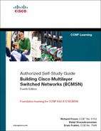
Recall from Chapter 4 that a VLAN is a logical group of ports, usually belonging to a single IP subnet to control the size of the broadcast domain. Because VLANs isolate traffic to a defined broadcast domain and subnet, network devices in different VLANs cannot communicate with each other natively. In Figure 8-1, VLANs 10, 20, and 30 cannot communicate with each other without the use of a Layer 3 device.
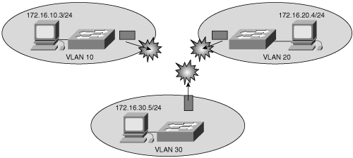
The devices in each VLAN can communicate to the network devices in another VLAN only through a Layer 3 routing device, referred to as an inter-VLAN router (see Figure 8-2). Cisco recommends the implementation of Layer 3 routing and switching in the Building Distribution submodule or the Building Access submodule of the multilayer switched network to terminate local VLANs. This helps to isolate network problems and to prevent them from affecting the Campus Backbone submodule. In addition, packet manipulation and control of the traffic across VLANs is simplified by routing in the distribution layer instead of the core layer.
The following devices are capable of providing inter-VLAN routing:
Any Layer 3 multilayer Catalyst switch
Any external router with an interface that supports trunking (router on a stick)
Any external router or group of routers with a separate interface in each VLAN
Note
Adding an external router with an individual interface in each VLAN is a nonscalable solution, especially when there are between 20 and 50 VLANs in the network. In addition, adding an external router for inter-VLAN routing on trunk interfaces does not scale beyond 50 VLANs. This chapter discusses only using Layer 3 switches and external routers with trunk interfaces (router on a stick) to route VLANs. Furthermore, Cisco IOS routers support trunking in specific Cisco IOS Software feature sets, such as the IP Plus Feature set. Refer to the documentation on Cisco.com for software requirements before deploying inter-VLAN routing on Cisco IOS routers.
Router on a stick is simple to implement because routers are usually available in every network, but most enterprise networks use multilayer switches to achieve high packet-processing rates using hardware switching. Recall from Chapter 1, “Introduction to Building Cisco Multilayer Switched Networks,” that hardware switching yields line-rate performance, scalability, and high availability. In addition, Layer 3 switches usually have packet-switching throughputs in the millions of packets per second (pps), whereas traditional general-purpose routers provide packet switching in the range of 100,000 pps to just over 1 million pps.
Many Cisco Catalyst switches support inter-VLAN routing either using integrated Layer 3 modules or with daughter cards. Table 8-1 lists the current models of Cisco Catalyst switches and identifies their inter-VLAN routing capabilities and solutions.
Table 8-1. Cisco Catalyst Switches with Inter-VLAN Routing Support
Type of Switch | Inter-VLAN Routing Capability | Inter-VLAN Routing Solutions |
|---|---|---|
Catalyst 2940/2950/2955/2960/2970 | No | |
Catalyst 3550/3750/3760 | Yes | Integrated |
Catalyst 4000/4500/4948 | Yes | Catalyst 4000 running Cisco CatOS with Supervisor I, II, using the Layer 3 module, WS-X4232-L3 Catalyst 4000 with a Supervisor II+, III, IV, or V running Cisco IOS using integrated routing |
Catalyst 6500 | Yes | Catalyst 6500 with an MSFC, MSFC II, or MSFC III daughter card running Cisco CatOS on the supervisors and Cisco IOS on the MSFC Catalyst 6500 with MSFC, MSFC II, or MSFC III running Cisco Native IOS Catalyst 6500 using a legacy MSM module |
Multilayer switches allow for the configuration of interfaces as Layer 2 or Layer 3 interfaces to provide all solutions in one switch. This book discusses Layer 2 interfaces in detail in Chapter 4. The following list is a summary of Layer 2 interfaces and their functionality:
Access port—. Carries traffic for a single VLAN
Trunk port—. Carries traffic for multiple VLANs using Inter-Switch Link (ISL) encapsulation or 802.1Q tagging
In Cisco IOS, the switchport command configures an interface as a Layer 2 interface. The no switchport command configures an interface as a Layer 3 interface. Note that different models of Catalyst switches use different default settings for interfaces. For example, all members of the Catalyst 3550 and 4500 families of switches use Layer 2 interfaces by default, whereas members of the Catalyst 6500 family of switches running Cisco IOS use Layer 3 interfaces by default. Recall that default interface configurations do not appear in the running or startup configuration. As a result, depending on which Catalyst family of switches is being used, the switchport or no switchport command may or may not be present in the running-config or startup-config files. In Cisco CatOS, all interfaces are Layer 2 interfaces.
The Catalyst multilayer switches support three different types of Layer 3 interfaces:
Routed port—. A pure Layer 3 interface similar to a routed port on a Cisco IOS router.
Switch virtual interface (SVI)—. A virtual VLAN interface for inter-VLAN routing. In other words, SVIs are the virtual routed VLAN interfaces.
Bridge virtual interface (BVI)—. A Layer 3 virtual bridging interface.
With the advent of high-performance switches such as the Catalyst 6500 and Catalyst 4500, almost every function, from spanning tree to routing, is done through hardware switching using features such as MLS and Cisco Express Forwarding (CEF)-based MLS, both of which are discussed in detail in later chapters.
All Layer 3 Cisco Catalyst switches support routing protocols, but several models of Catalyst switches require enhanced software for specific routing protocol features. Table 8-2 illustrates the types of Catalyst switches that support routing and the types of routing protocols they support.
Table 8-2. Routing Protocol Support for Cisco Catalyst Layer 3 Switches
Model of Layer 3 Catalyst Switch | Routing Protocols | Notes |
|---|---|---|
Catalyst 3550/3560/3750/3760 | RIP, OSPF, IGRP, EIGRP, BGP, etc. | If the switch is running a Standard Multilayer Software Image (SMI), only default routing, static routing, and RIP are supported. All other routing protocols require the Enhanced Standard Multilayer Software Image (EMI). |
Catalyst 4000/4500/4948 | RIP, OSPF, IGRP, EIGRP, BGP, etc. | With Cisco IOS, the Catalyst 4000/4500 with a Supervisor III, IV, and V require a special license to run BGP, EIGRP, OSPF, and IGRP. Catalyst 4000/4500 with a Supervisor II+ supports only static routes and RIP versions 1 and 2. With the WS-X4232-L3 routing module, BGP is not supported. |
Catalyst 6500 | RIP, OSPF, IGRP, EIGRP, BGP, etc. | BGP, Exterior Gateway Protocol (EGP) and IS-IS, etc., require the InterDomain Routing Feature License. |
A routed port is a physical port that acts similarly to a port on a traditional router with Layer 3 addresses configured. Unlike an access port, a routed port is not associated with a particular VLAN. A routed port behaves like a regular router interface, except that it does not support subinterfaces as with Cisco IOS routers.
Routed ports are used for point-to-point links; connecting WAN routers and security devices are examples of the use of routed ports. In the multilayer switched network, routed ports are mostly configured between the switches in the Campus Backbone submodules and between switches in the Campus Backbone and Building Distribution submodules if Layer 3 routing is applied in the distribution layer. Figure 8-3 illustrates an example of routed ports for point-to-point links in a multilayer switched network.
To configure routed ports, make sure to configure the respective interface as a Layer 3 interface using the no switchport interface command, if the default configurations of the interfaces are Layer 2 interfaces as with the Catalyst 3550 family of switches. In addition, assign an IP address and other Layer 3 parameters as necessary. After assigning the IP address, make certain that IP routing is globally enabled and that applicable routing protocols are configured. Note that routed ports are available only in Cisco IOS.
Note
Entering the no switchport interface configuration command shuts down the interface and then re-enables it, which might generate messages on the device to which the interface is connected. When you use this command to put the interface into Layer 3 mode, you delete any Layer 2 characteristics configured on the interface.
Example 8-1 illustrates the configuration of routed ports for a Catalyst 6500 switch running Cisco IOS. In this example, if the port is a Layer 2 port, the switch returns an error message upon attempted configuration.
Example 8-1. Configuration of Routed Ports in Cisco IOS
Core(config)#interface GigabitEthernet 1/1
Core(Coreonfig-if)#no switchport
Core(config-if)#ip address 10.10.1.1 255.255.255.252
Core(config-if)#exit
Core(config)#interface GigabitEthernet 1/2
Core(config-if)#ip address 10.20.1.254 255.255.255.252
% IP addresses may not be configured on L2 links.
Core(config-if)#no switchport
Core(config-if)#ip address 10.20.1.254 255.255.255.252
Core(config-if)#end
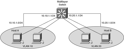
Switch virtual interfaces (SVI) are Layer 3 interfaces that are configured on multilayer Catalyst switches that are used for inter-VLAN routing. An SVI is a VLAN interface that is associated with only one (that is, a unique) VLAN-ID to enable routing capability on that VLAN, as shown in Figure 8-4. In Figure 8-4, to configure communication between VLANs, such as VLAN 10 and VLAN 20, you must configure each SVI with an IP address and subnet mask in the chosen address range for that subnet. The IP address associated with the VLAN interface is the default gateway of the workstation. In this case, the switch routes frames from host A to host B directly on the switch via hardware switching without requiring an external router. An SVI is mostly implemented to interconnect the VLANs on the Building Distribution submodules or the Building Access submodules in the multilayer switched network.
To configure an SVI for inter-VLAN routing on a Catalyst switch, such as the Catalyst 6000 Series, perform these steps:
(Optional.) Enable IP routing on the router.
Switch(config)#ip routing(Optional.) Specify an IP routing protocol or use static routes.
Switch(config)#router ip_routing_protocol options
Specify an SVI by using a VLAN interface command.
Switch(config)#interface vlan vlan-id
Assign an IP address to the VLAN.
Switch(config-if)#ip address ip_address subnetmask
Enable the interface.
Switch(config-if)#no shutdown
Example 8-2 shows the configuration of IP routing on a Catalyst 6500 by creating VLAN interfaces and assigning IP addresses and subnet masks to the interfaces.
Example 8-2. Inter-VLAN Routing Using SVIs
Switch#configure terminal
Enter configuration commands, one per line.  End with CNTL/Z.
Switch(config)#ip routing
Switch(config)#router rip
Switch(config-router)#network 10.0.0.0
Switch(config)#interface vlan 10
Switch(config-if)#ip address 10.10.1.1 255.0.0.0
Switch(config-if)#no shutdown
Switch(config-if)#interface vlan 20
Switch(config-if)#ip address 10.20.1.1 255.255.255.0
Switch(config-if)#no shutdown
Note
Make sure that VLANs are present in the VLAN database before creating SVI (VLAN) interfaces. Interfaces do not forward traffic for a VLAN until the VLAN is present in the VLAN database.
After applying the configuration shown in Example 8-2, hosts in VLAN 100 can communicate with hosts in VLAN 200 if each host is configured with a default gateway of the respective VLAN interface.
The number of routed ports and SVIs supported by the Layer 3 Catalyst switches is not limited by software; however, the relationship between the number of routed ports and the number of Layer 3 interfaces and other features might affect CPU utilization because of hardware limitations. One such example is NAT, because several models of Catalyst switches do not support NAT in hardware. Most Catalyst families of switches have different limitations with regard to the number of SVIs supported. In addition, the number of VLANs and SVIs supported per Catalyst family is not always the same. For example, a switch may support 256 VLAN, but only 64 SVIs (routed VLAN interfaces). Refer to Chapter 4 for details about the number of VLANs supported per Catalyst switch, and always refer to product release notes for the latest details about the number of VLANs and SVIs supported per Catalyst family of switch.
A bridge virtual interface (BVI) is a Layer 3 virtual interface that acts like a normal SVI to route packets across bridged or routed domains. Bridging Layer 2 packets across Layer 3 interfaces is a legacy method of moving frames in a network. To configure a BVI to route, use the integrated routing and bridging (IRB) feature, which makes it possible to route a given protocol between routed interfaces and bridge groups within the same device. Specifically, routable traffic is routed to other routed interfaces and bridge groups, while local or unroutable traffic is bridged among the bridged interfaces in the same bridge group. As a result, bridging creates a single instance of spanning tree in multiple VLANs or routed subnets. This type of configuration complicates spanning tree and the behavior of other protocols, which in turn makes troubleshooting difficult.
In today’s network, however, bridging across routed domains is highly discouraged. A BVI is useful for migrating bridged networks to routed networks, while hosts on the bridged networks can reach hosts on the routed network during the migration phase.
Only Cisco IOS routers support BVIs. The exceptions to this rule are the Catalyst 2948G-L3 and 4908G-L3 switches and the WS-X4232 Layer 3 module for the Catalyst 4000 switches. These switches use BVIs in place of SVIs for configuration. However, these switches are the only models to use BVIs instead of SVIs. In addition, Cisco intends to have all future models of Catalyst switches use the SVI method of configuring inter-VLAN routing. Again, except for the Catalyst 2948G-L3 and 4908G-L3 switches and the WS-X4232 Layer 3 module, BVIs are not supported on multilayer switches, and the use of BVIs on Cisco IOS routers is discouraged.
Moreover, several Catalyst multilayer switches support fallback bridging methods of forwarding traffic between VLANs. Fallback bridging forwards traffic not routed by the switch, such as SNA, and connects multiple VLANs into one bridge domain by bridging between two or more SVIs or routed ports. As a result, bridging the spanning tree in multiple VLANs creates a single instance of spanning tree for all VLANs. When configuring fallback bridging, you assign SVIs or routed ports to bridge groups, with each SVI or routed port assigned to only one bridge group. All interfaces in the same group belong to the same bridge domain. Cisco does not recommend this practice, however. Instead, it recommends using fallback bridging exclusively for migration because of the hardware-switching limitations of fallback bridging, confusing spanning-tree topologies, and other factors that make troubleshooting difficult.
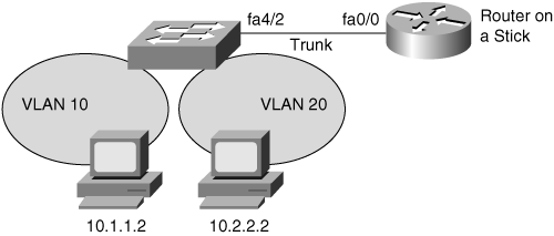
An alternative method of implementing inter-VLAN routing is to use an external router, referred to as router on a stick. The router on a stick feature requires the use of trunking using either ISL or 802.1Q between the external router and the Catalyst switch. Most of the newer switches only support 802.1Q because it is an open standard. A single trunk can carry traffic for multiple VLANs.
When implementing the 802.1Q trunk, it is important to make sure that the native VLAN is assigned to the same VLAN on each link partner. Refer to Chapter 4 for additional details on configuring trunking on Catalyst switches.
In Figure 8-5, the host on VLAN 10 needs to establish IP TCP sessions with the host on VLAN 20. To perform inter-VLAN routing functions, the router must know how to reach all interconnecting VLANs. As a result, the router must have a separate logical connection for each VLAN using ISL or 802.1Q trunking on a single physical connection. The router then performs the inter-VLAN function in the following way:
Each host sends traffic for other subnets to its default gateway, which is a router configured for routing between VLAN 10 and VLAN 20 through a switch.
The switch accepts the packets from each VLAN and forwards them to the router with encapsulation or tag for the proper VLAN.
The router accepts the packets from each VLAN because the route processor is configured to route traffic between VLANs 10 and 20.
The router determines the egress interface and VLAN based on the destination Layer 3 network address.
The router rewrites the Layer 2 source and destination MAC address and Layer 2 CRC and then tags or encapsulates the packet to identify the appropriate VLAN.
The router places the packet in the output queue of the appropriate egress interface for transmission to the switch; the switch then forwards the packet to the appropriate egress host port.
Note
When a host sends traffic to other subnets in a router on a stick configuration, it sends the traffic to the default gateway, which is the IP address of the subinterface configured on the external router (router on a stick). This behavior is the same as the use of SVIs configured on an internal router or Layer 3 switch.
To configure inter-VLAN routing using router on a stick, perform the following steps:
Enable trunking on the switch port connecting to the router. (Refer to Chapter 4 for details on configuring trunking on multilayer switches.)
Enable the router interface by issuing the no shutdown interface command on the router.
router(config)#interface {FastEthernet | GigabitEthernet} slot/port
router(config-if)#no shutdown
On the router, create the subinterfaces for each VLAN that requires inter-VLAN routing.
router(config)#interface {FastEthernet | GigabitEthernet}
slot/port.subinterface
On the router, configure the trunking encapsulation and IP address on the subinterfaces corresponding to the VLANs.
router(config-subif)#encapsulation [dot1Q | isl] vlan-id {native}
router(config-subif)#ip address ip_address subnet_mask
Note
The encapsulation dot1Q 1 native command was introduced in Cisco IOS version 12.1(3)T. The native keyword indicates the native VLAN. Recall from Chapter 4 that Cisco switches and routers do not tag the native VLAN. The alternative method of configuring the native VLAN is to configure the Layer 3 properties, such as the IP address, on the main interface rather than on the subinterface.
Note
The subinterface number of the slot/port number configuration is arbitrary and does not have to match the encapsulation configuration. However, to make configuration easily readable, configure the subinterface ID number as the VLAN ID number.
Example 8-3 shows an example of configuring inter-VLAN routing on an external router and a Catalyst switch running Cisco IOS. Configuration of a router is followed by the switch configuration to configure an interface as a trunk port.
Example 8-3. Inter-VLAN Routing Using External Router
Router(config)#interface FastEthernet0/0
Router(config-if)#no shutdown
Router(config)#interface FastEthernet 0/0.1
Router(config-subif) description VLAN 1
Router(config-subif)#encapsulation dot1Q 1 native
Router(config-subif)#ip address 10.1.1.1 255.255.255.0
Router(config-subif)#exit
Router(config)#interface FastEthernet 0/0.2
Router(config-subif)# description VLAN 2
Router(config-subif)#encapsulation dot1Q 2
Router(config-subif)#ip address 10.2.2.1 255.255.255.0
Router(config-subif)#exit
Router(config)#end
#####Cisco IOS switch Trunking Configuration Connected to Interface FastEthernet0/0
switch(config)#interface FastEthernet 4/2
switch(config-if)#switchport trunk encapsulation dot1q
switch(config-if)#switchport mode trunk
switch(config-if)#end
To verify the inter-VLAN routing configuration, use the ping command and the show commands. The following are the most useful commands for verifying inter-VLAN routing configurations:
ping
show running-config
show ip route
show ip protocol
After the router is properly configured and is connected to the network, it can communicate with other nodes on the network. To test IP connectivity to hosts, use the ping command.
To display and verify the current (running) configuration, IP routing information, and IP protocol information, use show commands. Example 8-4 displays the inter-VLAN configuration using the show running-config command.
In Example 8-5, the show ip route command shows the available IP routes in the router or multilayer switch.
Example 8-5. show ip route Command
Switch#show ip route
Codes: C -connected,S -static,I -IGRP,R -RIP,M -mobile,B -BGP
D -EIGRP,EX_-EIGRP external,O -OSPF,IA -OSPF inter area
N1 -OSPF NSSA external type 1,N2 -OSPF NSSA external type 2
E1 -OSPF external type 1, E2 -OSPF external type 2, E -EGP
I -IS-IS,L1 -IS-IS level-1,L2 -IS-IS level-2,ia -IS-IS inter area
* -candidate default,U -pre-user static route,o -ODR
P -periodic downloaded static route
Gateway of last resort is not set
10.100.0.0/24 is subnetted, 5 subnets
C  10.100.11.0 is directly connected, Vlan11
C  10.100.12.0 is directly connected, Vlan12
C  10.100.13.0 is directly connected, Vlan13
C  10.100.14.0 is directly connected, Vlan14
C  10.100.1.0 is directly connected, Vlan1
The show ip protocol command shows information about the routing protocols that are enabled on the switch or router, as shown in Example 8-6.
Example 8-6. show ip protocol Command
Switch#show ip protocol
Routing Protocol is "eigrp 1"
  Outgoing update filter list for all interfaces is not set
  Incoming update filter list for all interfaces is not set
  Default networks flagged in outgoing updates
  Default networks accepted from incoming updates
  EIGRP metric weight K1=1, K2=0, K3=1, K4=0, K5=0
  EIGRP maximum hopcount 100
  EIGRP maximum metric variance 1
  Redistributing: eigrp 1
  Automatic network summarization is in effect
  Maximum path: 4
  Routing for Networks:
    10.0.0.0
  Passive Interface(s):
    Vlan1
    Vlan11
    Vlan12
    Vlan13
    Vlan14
  Routing Information Sources:
    Gateway         Distance      Last Update
    10.100.117.202        90      20:25:10
    10.100.113.201        90      20:25:10
    Gateway         Distance      Last Update
    10.100.115.202        90      20:25:12
10.100.111.201        90      20:25:12
  Distance: internal 90 external 170
IP broadcast forwarding is necessary when using VLANs to centrally locate DHCP or other servers where clients rely on broadcasts to locate or communicate with the services running on the server. For example, DHCP requests are IP subnet broadcasts to the 255.255.255.255 address. Routers do not route these packets by default. However, Cisco routers and Layer 3 switches can be configured to forward these DHCP and other UDP broadcast packets to a unicast or directed broadcast address. The broadcast-forwarding features support more than DHCP and can forward any UDP broadcast. Another example of using IP broadcast forwarding is to forward NetBIOS over IP broadcasts for Microsoft Windows clients that are not using WINS servers.
The following list summarizes the solutions that Cisco IOS IP broadcast forwarding features provide:
DHCP relay agent
UDP broadcast forwarding
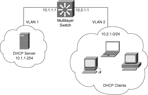
DHCP is a client-server application, in which the DHCP client, usually a desktop computer, contacts a DHCP server for configuration parameters using a broadcast request. Today’s enterprise networks consist of multiple VLANs, where inter-VLAN routing routes between the subnetworks. Because Layer 3 devices do not pass broadcasts by default, each subnet requires a DHCP server unless the routers are configured to forward the DHCP broadcast using the DHCP relay agent feature, as shown in Figure 8-6.
To enable the DHCP relay agent feature, configure the ip helper-address command with the DHCP server IP address on the client VLAN interfaces on Cisco Catalyst multilayer switches or on router interfaces in the router on a stick scenario. For multiple DHCP servers, use multiple commands. The ip helper-address command not only forwards DHCP UDP packets but also forwards TFTP, DNS, Time, NetBIOS, name server, and BOOTP packets by default.
Example 8-7 illustrates the configuration of the DHCP relay agent feature using the ip helper-address command, as shown in Figure 8-6. In this example, 10.1.1.254 is the DHCP server that resides in VLAN 1 and hosts the DHCP clients that reside on VLAN 2 in the 10.1.2.0/24 network.
Example 8-7. Sample Configuration of DHCP Relay Agent
6500(config)#interface vlan 1
 6500(configif)#description DHCP Server VLAN
6500(config-if)#ip address 10.1.1.1 255.255.255.0
6500(config-if)#no ip directed-broadcast
6500(config-if)#no shutdown
6500(config-if)#interface vlan 2
6500(config-ig)#description DHCP clients
6500(config-if)#ip address 10.2.1.1 255.255.255.0
6500(config-if)#no shutdown
6500(config-if)#no ip directed-broadcast
6500(config-if)#ip helper-address 10.1.1.254
6500(config-if)#exit
Note
When applying the ip helper-address command, make sure the ip directed-broadcast is not configured on any outbound interface that the UDP broadcast packets need to traverse. The no ip directed-broadcast command configures the router or switch to prevent the translation of a directed broadcast to a physical broadcast. This is a default behavior since Cisco IOS Release 12.0, implemented as a security measure. For more information, consult the following document:
http://www.cisco.com/warp/public/707/21.html Document ID: 13608
To specify additional UDP broadcasts for forwarding by the router when configuring the ip helper-address interface command, use the following command:
ip forward protocol udp udp_ports
You can also use this command to configure the router not to forward UDP broadcasts for specific ports. Table 8-3 shows the default UDP ports forwarded by the configuration of the ip helper-address command.
Example 8-8 illustrates the configuration to disallow the forwarding UDP broadcasts for the NetBIOS name service, a default behavior when configuring the ip helper-address command. This example also shows the configuration of forwarding UDP packets for mobile-ip and the other default UDP forwarded ports.
Example 8-8. ip forward-protocol udp Command
Router(config)#interface vlan 2
Router(config-if)#ip address 10.2.1.1 255.255.255.0
Router(config-if)#ip helper-address 10.1.1.254
Router(config-if)#no shutdown
Router(config-if)#exit
Router(config)#no ip forward-protocol udp netbios-ns
Router(config)#ip forward-protocol udp mobile-ip
The following bullets review important BCMSN exam preparation points of this chapter. The bullets only briefly highlight the important concepts. Consult the text of this chapter for additional information regarding these topics. Table 8-4, which follows this list, provides a summary of the key commands covered in this chapter:
Inter-VLAN routing is required to route traffic between VLANs. Without inter-VLAN routing, VLANs are simple LAN islands.
The three available solutions for inter-VLAN routing are Layer 3 switching, router on a stick, and external router without trunking. Most enterprise and service provider networks use Layer 3 switching.
Layer 3 switching, compared to other inter-VLAN routing solutions, provides the highest packet-forwarding rate with the most features.
In multilayer switched networks, SVIs are best suited for Distribution or Access submodules.
Routed interfaces are mainly used for connecting Distribution submodules and Campus Backbone submodules. Routed interfaces commonly use IP address with 30-bit subnet masks.
IP routing is a global configuration option on all Layer 3 switches.
Make sure to create VLANs in the VLAN database before creating SVI (VLAN) interfaces. Interfaces do not forward traffic for a VLAN until the VLAN is present in the VLAN database.
The recommended practice is not to bridge across VLANs unless necessary because doing so can create Layer 2 loops, make troubleshooting and topology rendering difficult, and might cause latency issues because packet flow does not follow the hardware-switching path on most Catalyst switches.
Most Cisco Catalyst Layer 3 switches support all routing protocols; however, they might require special software licenses for specific routing protocols such as BGP.
To forward DHCP requests to a DHCP server on different VLANs or subnets, configure the DHCP relay agent on first-hop Layer 3 interfaces by using the ip helper address command on the VLAN interfaces.
Table 8-4. Commands to Review
Command | Description |
|---|---|
interface vlan vlan-id | Configures an SVI for a specific VLAN for Layer 3 routing. |
interface {fastethernet | gigabitethernet} slot/port.subinterface | Creates a subinterface corresponding to a specific VLAN on an Ethernet interface of a Cisco IOS router. This command is not used on Layer 3 switches. |
encapsulation [dot1Q | isl] vlan-id {native} | Configures trunking on Ethernet subinterfaces of a router. The native keyword specifies that the subinterface operates on the native VLAN. |
show ip route | Displays the current routing table of a Cisco router or switch. |
show ip protocol | Displays information about the routing protocols currently enabled on a Cisco router or switch. |
ping | Tests connectivity between two or more IP-enabled devices. |
ip helper-address dhcp-ip-address | Configures the DHCP relay agent’s destination IP address for forwarding DHCP broadcast request across Layer 3 boundaries. This feature might be used for more than just DHCP broadcasts. In addition, the destination IP address can be unicast, multicast, or broadcast. |
ip forward-protocol udp udp-ports | Configures additional UDP ports, besides the default ports, on a router or switch for forwarding UDP broadcast across a Layer 3 boundary. |
This chapter discussed in detail Layer 3 routing and its implementation, including coverage of inter-VLAN routing and router on a stick. This chapter can be summarized as follows:
Inter-VLAN routing provides communication between the devices in different VLANs. Recall that a VLAN is a single broadcast domain, and the devices within a VLAN are not able to communicate beyond VLAN boundaries unless through a Layer 3 device. Multilayer switches support two types of Layer 3 interfaces: routed ports and SVIs (VLAN interfaces).
Routed ports are point-to-point connections such as those that interconnect the Building Distribution submodules and the Campus Backbone submodules when using Layer 3 in the distribution layer.
SVIs are VLAN interfaces that route traffic between VLANs, and VLANs group ports together. In multilayer switched networks with Layer 3 in the distribution layer and Layer 2 in the access layer, SVIs are used to route traffic from VLANs on the access-layer switches.
Using router on a stick is an alternative and legacy method of implementing inter-VLAN routing for low-throughput and latency-tolerant applications.
Complete this configuration exercise to familiarize yourself with the initial configuration of inter-VLAN routing on Cisco IOS–based Catalyst switches.
The only resource necessary for this lab exercise is access to a Cisco IOS–based Catalyst switch via the console or in-band access such as SSH. A host workstation for testing the configuration of inter-VLAN routing is optional.
The purpose of this exercise is to demonstrate the configuration of inter-VLAN routing in the multilayer switched environment. After completing this exercise, you will be able to perform the following types of configurations on Catalyst switches running Cisco IOS:
Configure inter-VLAN routing in the distribution submodule switches using SVIs.
Configure simple routing using EIGRP.
Configure inter-VLAN routing on the external router using router on a stick.
Configure SVI interfaces for DHCP forwarding.
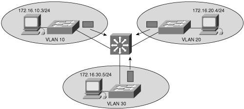
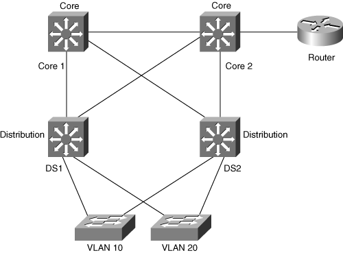
Figure 8-7 shows the network layout for this configuration exercise.
In this configuration exercise, you use the commands listed in Table 8-5. These commands are in alphabetical order so that you can easily locate the information you need. Refer to this list if you need configuration command assistance during the exercise. The table includes only the specific parameters used in the example and not all the available options for the command.
Table 8-5. Command List for Configuration Exercise
Command | Description |
|---|---|
configure terminal | Enters global configuration mode. |
enable password password | Sets the password used to move into privileged EXEC mode. |
encapsulation dot1q | isl vlan-id | Enables trunking and identifies the VLAN for a subinterface on a Cisco IOS router. This command is not used on Layer 3 Catalyst switches. |
exit | Exits the current mode. |
interface fastEthernet | gigabitEthernet slot/port | Enters the interface configuration mode for a Catalyst switch with a Fast Ethernet or Gigabit Ethernet interface installed. slot refers to the module number, and port refers to the front-panel port number. |
interface fastEthernet | gigabitEthernet slot/port.number | Creates a subinterface on an interface of a router. Used for configuring a router on a stick. |
interface vlan vlan-id | Creates the VLAN interface for inter-VLAN routing. |
ip address address subnetmask | Specifies the IP address for an interface. |
ip helper-address dhcp-server-address | Forwards DHCP requests packets across the routed network. |
network network_address | Enables routing on the networks. |
no interface vlan vlan-id | Removes the VLAN interface. |
no ip directed-broadcast | Configures the router or switch to prevent the translation of a directed broadcast to a physical broadcast. By default, routers are configured with the no ip directed-broadcast configuration. |
no switchport | Configures an interface as a Layer 3 routed port; an interface is required to be a Layer 3 routed port to accept an IP address. |
ping ip-address | Sends an ICMP echo to the designated IP address using the default size and response window time settings. |
router eigrp process-id | Initiates EIGRP on the Layer 3 switches and routers with a specific process ID. Also enters the EIGRP configuration submode for configuring additional EIGRP parameters. The process-id is globally significant and should match all EIGRP routers in the AS. |
show interfaces [type slot/port] switchport | Displays the switchport configuration of the interface. |
show interfaces trunk | Displays the trunk configuration of the interface. |
[no] shutdown | Administratively shuts down or enables an interface. |
switchport access vlan vlan-id | Specifies the default (native) VLAN, which is used if the interface is not trunking. |
switchport mode trunk | Puts the interface into permanent trunking mode and negotiates to convert the link into a trunk link. |
switchport trunk allowed vlan remove vlan-list | Configures the list of VLANs allowed on the trunk. |
switchport trunk encapsulation dot1q | Specifies 802.1Q encapsulation explicitly on a trunk link. |
switchport trunk encapsulation isl | Specifies ISL encapsulation explicitly on a trunk link. |
telnet ip-address | Starts a terminal-emulation program from a PC, router, or switch that permits you to access network devices remotely over the network. |
vlan database | Enters VLAN configuration mode. |
vlan vlan-id | Creates a VLAN in the VLAN database and enters the VLAN configuration mode. |
Connect to Building Distribution switches DS1 and DS2. Enter privileged EXEC mode using the enable command, and then enter global configuration mode using the configure terminal command.
From global configuration mode, create VLAN virtual interfaces for VLAN 10 and VLAN 20 on each of the Building Distribution switches to enable inter-VLAN routing. The following is the configuration of Building Distribution switch DS1. Use the same steps for DS2, but with the appropriate IP addresses.
ds1(config)#ip routing
ds1(config)#interface vlan 10
ds1(config-if)#ip address 10.10.1.1 255.255.255.0
ds1(config-if)#no shutdown
ds1(config-if)#interface vlan 20
ds1(config-if)#ip address 10.20.1.1 255.255.255.0
ds1(config-if)#no shutdown
ds1(config-if)#end
Configure EIGRP as the routing protocol on all the Building Distribution and Building Core switches. Consult Cisco.com for additional information regarding routing protocols:
DS1(config)#router eigrp 1
DS1(config-router)#network 10.0.0.0
Verify that the switches are learning routes in the routing table using EIGRP by using the show ip route command:
DS1#show ip route
3w0d: %SYS-5-CONFIG_I: Configured from console by consoleoute
Codes: C - connected, S - static, I - IGRP, R - RIP, M - mobile, B - BGP
       D - EIGRP, EX - EIGRP external, O - OSPF, IA - OSPF inter area
       N1 - OSPF NSSA external type 1, N2 - OSPF NSSA external type 2
       E1 - OSPF external type 1, E2 - OSPF external type 2, E - EGP
       i - IS-IS, L1 - IS-IS level-1, L2 - IS-IS level-2, ia - IS-IS inter
       * - candidate default, U - per-user static route, o - ODR
       P - periodic downloaded static route

Gateway of last resort is not set
        10.0.0.0/8 is variably subnetted, 2 subnets, 2 masks
     C       10.10.1.0/24 is directly connected, VLAN10
     C       10.20.1.0/24 is directly connected, VLAN20
     D       10.1.2.0/24 [90/2169856] via 10.1.1.1, 00:00:47,
GigabitEthernet1/2
Configure trunking on the Layer 2 Cisco IOS switch.
Core2(config)#interface FastEthernet 4/6
Core2(config-if)#switchport trunk encapsulation dot1q
Core2(config-if)#switchport mode trunk
Configure inter-VLAN routing on the external 2600 router.
Router(config)#interface FastEthernet 0/1
Router(config-if)#no shutdown
Router(config)#int FastEthernet 0/1.1
Router(config-subif)#encapsulation dot1Q 1 native
Router(config-subif)#ip address 10.1.1.1 255.255.255.0
Router(config-subif)#no shutdown
Router(config-subif)#interface FastEthernet 0/1.2
Router(config-subif)#encapsulation dot1Q 2
Router(config-subif)#ip address 10.2.1.1 255.255.255.0
Router(config-subif)#no shutdown
Router(config-subif)#end
Configure the Building Distribution switches for DHCP forwarding because hosts that reside on the Access Layer switches used DHCP to get their IP addresses, default gateway, and so on.
ds1(config)#interface vlan 10
ds1(config-if)#no ip directed-broadcast
ds1(config-if)#ip helper-address 10.2.1.254
ds1(config-if)#interface vlan 20
ds1(config-if)#no ip directed-broadcast
ds1(config-if)# ip helper-address 10.2.1.254
For multiple-choice questions, there might be more than one correct answer.
True or False: A SVI is a physical Layer 3 interface, whereas a routed port is a virtual Layer 3 interface. | |
True or False: Multilayer switches generally outperform routers of multiple Ethernet interfaces. | |
True or False: A router can forward DHCP requests across VLAN or IP subnet boundaries by using the DHCP relay agent feature. Questions 4 and 5 are based on the configuration in Example 8-9. Example 8-9. Configuration for Questions 4 and 5 6500-5#show run interface vlan 10 Building configuration... Current configuration : 60 bytes ! interface Vlan10 ip address 10.1.1.1 255.255.255.0 no ip proxy-arp end 6500-5#show run int vlan 20 Building configuration... Current configuration : 60 bytes ! interface Vlan20 ip address 10.2.1.1 255.255.255.0 no ip proxy-arp end 6500-5# | |
Based on Example 8-9, can the hosts that reside in VLAN 20 communicate with hosts on VLAN 10 if their default gateway is set to 10.2.1.1?
| |
Based on Example 8-9, if the hosts that reside on VLAN 10 have their default gateway defined as 10.1.1.1 and can ICMP ping 10.2.1.1 but not a host that resides in VLAN 20, what could be a possible reason?
| |
What command is used on Cisco IOS switches to change the interface from a Layer 3 interface to a Layer 2 interface?
| |
Which Cisco IOS command enables IP routing on a Catalyst switch?
| |
What are the disadvantages of using BVIs on Cisco IOS routers? | |
What is the function of a DHCP relay agent? | |
Which of the following UDP protocols are forwarded in addition to DHCP when a Layer 3 interface is configured with the ip helper-address command? (Select all that apply.)
|