This chapter covers the following topics:
Catalyst 6500
Catalyst 4500
Catalyst 3750
Catalyst 3560
Catalyst 2960
Understanding the features and limitations of any Cisco Catalyst switch is critical in effectively deploying the switch in a multilayer switched network. Cisco Systems, Inc., has introduced many families of switches through the past years, from the Catalyst 5500 to the more recent Catalyst 4500 and 6500 families of switches. Each of these switches is designed for different functions in the multilayer switched network. For example, Catalyst 2960 switches are primarily designed for the Building Access submodule, whereas Catalyst 6500 switches are designed more for the Campus Backbone submodule. Designing the network with appropriate Catalyst switches for each of the core, distribution, and access layers is a critical success factor. Troubleshooting is another advantage of understanding the architecture; for troubleshooting complex problems, knowing the architecture is paramount.
This chapter goes beyond the description of Catalyst switches found in Chapter 1, “Introduction to Building Cisco Multilayer Switched Networks.” Chapter 1 focused on all performance, scalability, and availability options. This chapter focuses on performance and switching architectures. Upon completion of this chapter, you will understand the basics of the switching architecture on the Catalyst switches discussed, how to effectively place them in your network, and how to troubleshoot the switches.
Note
Most of this chapter is outside the spectrum of the CCNP certification exam. However, the concepts presented in this chapter are essential for a complete understanding of the Catalyst switches.
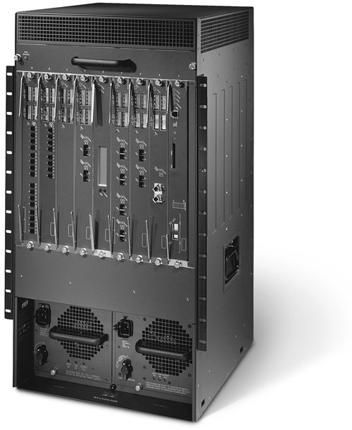
The Catalyst 6500 is the premier intelligent multilayer switch among the Cisco Catalyst family of products. The Catalyst 6500, used in Campus Backbone submodules, Building Distribution submodules, and the Enterprise Edge module, offers high-performance, scalability, and high-availability features such as Non-Stop Forwarding (NSF) with stateful switchover (SSO). The Catalyst 6500 family of switches also supports the Cisco modular IOS, which allows unprecedented availability and run-time patching capabilities. The Catalyst 6500 family of switches is also commonly deployed in every submodule, end-to-end, in large enterprise networks. Moreover, the Catalyst 6500 is a modular switch with different chassis options, as shown in Table 15-1.
Figure 15-1 shows a Catalyst 6509-NEB-A switch.
The Catalyst 6500 supports the following types of interfaces:
Fast Ethernet
Gigabit Ethernet
10-Gigabit Ethernet (10GE)
WAN interface through Enhanced FlexWAN modules and Shared Port Adapter Interface Processor (SIP) modules
In addition, the Catalyst 6500 provides many service modules, such as the following:
Content Services Gateway (CSG)
Application Control Engine (ACE)
Firewall Services Module (FWSM)
IPsec Shared Port Adapter (SPA) VPN Module (IVSM)
Intrusion Detection System Module (IDSM)
Network Analysis Module (NAM)
Anomaly Detection Module (ADM)
Anomaly Guard Module (AGM)
Communication Media Module (CMM)
Wireless Service Module (WiSM)
Catalyst 6500 Supervisor Engines are available in many different hardware configurations, as shown in Table 15-2.
Table 15-2. Catalyst 6500 Supervisor Engines
Supervisor Engine | Description |
|---|---|
WS-X6K-S2-PFC2 | Supervisor Engine II with Layer 3 engine (Note: End of Sale as of March 1, 2007) |
WS-X6K-S2-MSFC2 | Supervisor Engine II with MSFC2. (Note: End of Sale as of March 1, 2007) |
WS-SUP32-GE-3B | Supervisor Engine 32 with eight Gigabit Ethernet (GE) uplinks and PFC3B (includes MSFC2A) |
WS-SUP32-10GE-3B | Supervisor Engine 32 with two 10GE uplinks and PFC3B (includes MSFC2A) |
WS-SUP720-3B | Supervisor Engine 720 (includes MSFC3) |
In brief, Catalyst 6500 architecture supports the following data paths in the system:
Data bus (D-bus)—. The 32-Gbps full-duplex data bus (also known as classic bus) is available with all Supervisor Engines and chassis.
256-Gbps fabric—. The 256-Gbps full-duplex fabric requires the Supervisor Engine II, Switch Fabric Module, and specific model of line modules.
720-Gbps fabric—. The 720-Gbps full-duplex fabric is provided in addition to D-bus on Supervisor Engine 720–based systems only.
Catalyst 6500 line cards are also available in different hardware and performance configurations. Fabric line cards interface with the fabric module and might or might not have a connection to the D-bus, whereas the non-fabric module only interfaces with the D-bus. Table 15-3 illustrates the different types of line cards.
Table 15-3. Types of Line Cards on Catalyst 6500
Line Cards | Description | Example |
|---|---|---|
Non-fabric | Connects only to the backplane D-bus | WS-X6148A-RJ45 |
256-Gbps fabric enabled (single) with or without distributed forwarding option | Connects to D-bus and has one fabric connection (16-Gbps full duplex) | WS-6516-GBIC |
256-Gbps fabric only (dual) with Distributed Forwarding Card | Connects only to fabric through two connectors (16-Gbps full duplex each) | WS-X6816-GBIC |
720-Gbps fabric enabled with or without Distributed Forwarding Card | Connects to the D-bus and has two fabric connections (40-Gbps full duplex each) | WS-X6704-10GE |
The Supervisor Engine 32 features are similar to the Supervisor Engine 720 features but at a lower performance level, targeted for the access layer or WAN edge deployments. Supervisor Engine 32 uses a CEF forwarding mechanism. The performance of the Catalyst 6500 with Supervisor Engine 32 is limited to 15 million packets per second (Mpps).
Supervisor Engine 32 comes with the MSFC2A routing engine by default and consists of the following three components. The ingress module sends the received packet to the D-bus, which is seen and stored by other modules in their module ASIC buffers.
Network Management Processor (NMP)—. Maintains and controls the Layer 2 protocols, such as Spanning Tree Protocol, and line-card and system management communications.
Policy Feature Card 3B (PFC 3B)—. A Layer 3 forwarding ASIC controlled by the NMP and performs Layer 3 hardware switching, Quality of Service (QoS), and security ACL lookups.
Multilayer Switch Feature Card 2A (MSFC 2A)—. The router module performs routing with the assistance of NMP and PFC. The MSFC runs the router IOS and supports all the features of a normal router.
All modules in the chassis connect to the backplane D-bus through connectors. The Supervisor NMP module receives copies of every packet on the D-bus that it stores in a buffer while making forwarding decisions. NMP makes the forwarding decision on the packet based on the source and destination MAC, IP address, source and destination VLAN, security features, QoS, and other features configured on the system. After the decision has been made to either forward the frame or drop it; that decision is communicated to all the modules. Only the correct egress interfaces forward the traffic; the rest of the modules flush the packet from buffers. In other words, with a Supervisor Engine 32 in a Catalyst 6500, the switch copies ingress packets to every other module buffers, and the NMP signals exactly which ports forward the packet. The performance of this behavior is limited by the speed of the BUS and the NMP.
The Supervisor Engine II is the second-generation Supervisor Engine for the Catalyst 6500 platform. The Supervisor Engine II introduced CEF-based MLS on the Catalyst 6500 switch series. The details of CEF-based MLS are described in Chapter 9, “Understanding and Configuring Multilayer Switching.”
Note
Supervisor Engine II will go End of Sale (EoS) March 1, 2007. Newer deployments should use Supervisor Engine 720, which offers higher performance and throughput.
The Supervisor Engine II introduced support for the following features and components:
Switch Fabric Module (SFM)—. 256-Gbps full-duplex cross-bar fabric
Distributed Forwarding Card—. Provides distributed CEF-based MLS
With SFM and fabric-enabled line cards, the Supervisor Engine II can achieve forwarding rate increases up to 30 Mpps. With SFM and distributed fabric-enabled line cards, forwarding rates increase to 210 Mpps. Catalyst 6500 provides SFM redundancy in the case of active SFM failure with support for a standby SFM.
The SFM module plugs into specific dedicated slots on the chassis. Table 15-4 shows the location on various chassis models.
With non-fabric-enabled line cards, the operations are similar to the behavior described for the Supervisor Engine I–based systems.
With SFM, the packets are sent over the SFM if possible, because it is faster than the D-bus. SFM operates in one of the following modes:
Compact mode—. The most efficient mode of operation without DFC-equipped cards present in the chassis. Compact mode is achieved when all line cards in the chassis are fabric enabled, and packets traveling between modules flow through the fabric. Only a compact header with enough information is sent on the D-bus so that the Supervisor Engine can make the forwarding decision. The actual data frame is sent over the SFM yielding the improved performance.
Truncated mode—. Less efficient than Compact mode because one or more non-fabric-enabled line cards are present in the chassis. The non-fabric-enabled line card forces the fabric-enabled line cards to use the D-bus to communicate to these non-fabric-enabled cards. In this mode, the traffic between the fabric-enabled module and the non-fabric-enabled modules goes through the switch fabric channel to the Supervisor Engine, which then forwards the frame via D-bus to the destination module. In case of traffic between fabric-enabled modules, only the truncated data (the first 64 bytes of the frame) is sent over the switch fabric channel, and actual data goes through the fabric.
BUS mode—. Uses the D-bus for all traffic communication except when fabric-only line cards are present. Traffic between fabric-only line cards is switched through the Supervisor Engine to the D-bus to the destination module. BUS mode is the least efficient because its maximum forwarding rate is limited to 15 Mpps.
Distributed CEF 256 (dCEF256) mode—. Used when DFC-equipped line cards are present. If all the line cards are equipped with DFC, the combination with an SFM achieves the highest forward rate. DFC downloads the CEF-forwarding information from the Supervisor Engine (CEF-based MLS), and hence forwarding decisions are made locally on the line cards. If the source and destination of the traffic are local to the line card, then the DFC switches the packet locally without needing the full packet to go over the fabric or BUS. Only the truncated header is sent over the fabric to the Supervisor Engine for statistics purposes.
For more information about the SFM, refer to the following Cisco.com document:
“Understanding the Catalyst 6500 Switch Fabric Module with Supervisor Engine 2,” Document ID: 23221
http://www.cisco.com/en/US/products/hw/switches/ps700/products_tech_note09186a00801c6652.shtml
Supervisor Engine 720 is the third-generation Catalyst 6500 Supervisor Engine; the Supervisor Engine 720 includes an integrated fabric module and MSFC module where previous Supervisors used a separate line module for the fabric module. The highlight of this Supervisor Engine is the high forwarding capabilities—up to 400 Mpps over a 720-Gbps fabric.
Supervisor Engine 720 adds hardware-switching support for the following features in addition to features of Supervisor Engine II:
IPv6
IPv4 NAT
MPLS
GRE and IP in IP tunneling
Note
Supervisor Engine 720 uses the slot dedicated for SFM modules. Previous Supervisor Engines used slots 1 and 2.
The fabric connections of the line cards (6700 series) for Supervisor Engine 720 operate at 40-Gbps full duplex and hence provide the ability to support a high data rate through the module and the switch.
The Catalyst 6500 offers a variety of line modules suited for all environments. Table 15-5 lists and describes the most popular modules at press time. For a complete current list of all module types, refer to Cisco.com.
Table 15-5. List of Select Catalyst 6500 Modules
Description | |
|---|---|
WS-X6704-10GE | 4-port 10-Gigabit Ethernet Module with 40-Gigabit Fabric connectivity |
WS-X6708-10GE-3C/3C-XL | 8-port 10-Gigabit Ethernet Module with 40-Gigabit Fabric connectivity (2:1 oversubscribed) |
WS-X6724-SFP/WS-X6748-SFP | 24-port and 48-port SFP Gigabit Ethernet interface module with 40-Gigabit Fabric connectivity |
WS-X6748-GE-TX | 48-port 10/100/1000 Ethernet Module with 40-Gigabit Fabric connectivity |
WS-X6148A-GE-45AF | 48-port 10/100/1000 Ethernet Module with IEEE 802.3af support |
WS-X6148A-45AF | 48-port 10/100 Ethernet Module with IEEE 802.3af support |
The Catalyst 6500 also supports various types of service modules. Table 15-6 provides a brief description of each of these modules. For a complete current list of service modules and more information, refer to Cisco.com.
Table 15-6. Catalyst 6500 Services Modules
Service Module | Description |
|---|---|
Wireless Service Module (WS-SVC-WISM-1-K9) | Enables secure wireless LAN deployment with support for up to 10,000 wireless LAN users and 300 lightweight access points |
Persistent Storage Device (WS-SVC-PSD-1) | Provides an extension to the Cisco CSG storage to prevent loss of billing information due to failures to reach billing collections from CSG |
Multiprocessor WAN Application Module (WS-SVC-MWAM-1) | Enables service providers to deploy, provision, and manage value-added services at the network edge |
Content Services Gateway (WS-SVC-CSG-1) | Provides dynamic content examination, subscriber service access control, and subscriber account balance enforcement and provides the capability for billing, traffic analysis, and data mining in a highly scalable, fault-tolerant package in a service provider environment |
Communication Media Module (WS-SVC-CMM) | Provides high-performance and high-density Voice over IP (VoIP) gateways and Media Services |
Application Control Engine (ACE10-6500-K9) | Delivers the highest level of application infrastructure control, application performance, application security, and infrastructure simplification. ACE scales up to 16 Gbps throughput, 6.5 Mpps, and 4 million concurrent connections. |
Firewall Services Module (WS-SVC-FWM-1-K9) | Provides integrated 5.5 Gbps throughput, 100 connections per second, and 1 million concurrent connections using Cisco PIX technology. Up to 4 can be installed in a chassis to provide up to 20 Gbps throughput. |
Intrusion Detection System Module (WS-SVC-IDSM2-K9) | Enable organizations to protect their connected business assets from threats and increase the operating efficiency of intrusion protection |
Network Analysis Module (WS-SVC-NAM-2) | Provides integrated monitoring up to application layer level for both LAN and WAN environments |
Switches in the Catalyst 6500 family are widely deployed in multilayer switched networks and provide the highest forwarding performance rate among the Catalyst family of switches. They provide critical features such as security, high availability, and services that are necessary in enterprise and service provider environments.
Table 15-7 lists the recommended Catalyst 6500 deployment scenarios.
Table 15-7. Catalyst 6500 Deployment Scenarios
Supervisor Engine | Deployment Scenarios |
|---|---|
WS-SUP720-3B | Enterprise Campus Backbone and Building Distribution submodules, Data Center modules, and service provider networks |
WS-SUP32-10GE-3B and WS-SUP32-GE-3B | Enterprise Building Access submodules and Enterprise Edge |
The Catalyst 4500 family of switches is the second generation of the previous-generation Catalyst 4000 family of switches. Catalyst 4500 provides many of the features provided by Catalyst 6500, but with lower performance metrics and lower cost. The Catalyst 4500 architecture is based on low latency, centralized shared memory switching fabric, and centralized switching.
The Catalyst 4500 family of switches offers the following key features:
Supervisor Engine redundancy via NSF/SSO
Power supply redundancy
IEEE 802.3af PoE
102-Mpps performance capability
Full suite of QoS features
Superior Catalyst security features
The Catalyst 4500 is a modular switch with different chassis options, as shown in Table 15-8.
Note
The first generation Catalyst 4000 family of switches included the WS-C4003 (3-slot chassis) and WS-C4006 (6-slot chassis). The Catalyst 4500 family of switches listed in Table 15-8 replaces the first generation of the Catalyst 4000 family of switches.
Catalyst 4500 switches also offer fixed configuration models, as shown in Table 15-9, for high-end Data Center environments offering line-rate performance on all ports.
Similar to the Catalyst 6500, the Catalyst 4500 family of switches supports a range of Supervisor Engines, as shown in Table 15-10, offering different feature options.
Table 15-10. Catalyst 4500 Family of Switches Supervisor Engines
Supervisor Engine | Description |
|---|---|
WS-X4013+ | Supervisor Engine II+ provides Layer 2 and basic Layer 3 functionality (RIP and static routes along with QoS and security ACL support). Redundancy option available in 4507R and supported in 4006, 4503, and 4506 chassis. 64-Gbps switching capacity. 48-Mpps throughput. |
WS-X4013+ TS | Supervisor Engine II plus provides Layer 2 and basic Layer 3 functionality. Supported only on the Catalyst 4503 chassis. Provides 20 Gigabit Ethernet ports on the Supervisor Engine module. 64-Gbps switching capacity. 48-Mpps throughput. |
WS-X4013+10GE | Supervisor Engine II+ with two 10GE uplink ports provides Layer 2 and basic Layer 3 functionality (RIP and static routes along with QoS and security ACL support). Redundancy option available in 4507R and supported in 4006, 4503, and 4506 chassis. Up to 108-Gbps switching capacity. Up to 81-Mpps throughput. |
WS-X4515 | Supervisor Engine IV provides Layer 2 and Layer 3 functionality. NetFlow service card optionally available for NetFlow data collection. Redundancy option available in 4507R and supported in 4006, 4503, and 4506 chassis. 64-Gbps switching capacity. 48-Mpps throughput. |
WS-X4516 | Supervisor Engine V provides Layer 2 and Layer 3 functionality. NetFlow service card optionally available for NetFlow data collection. Redundancy option available in 4507R and 4510R and supported in 4503 and 4506. 96-Gbps switching capacity. 72-Mpps throughput. |
WS-X4516-10GE | Supervisor Engine V provides Layer 2 and Layer 3 functionality. Supports two 10GE uplinks or four 1-Gigabit Ethernet uplinks on the Supervisor. NetFlow service card integrated into the supervisor for NetFlow data collection. Redundancy option available in 4507R and 4510R and also supported in 4503 and 4506. 136-Gbps switching capacity. 102-Mpps throughput. |
All Catalyst 4500 Supervisor Engines run Cisco IOS. Each module on Catalyst 4500 is connected to the Supervisor Engine central ASIC through 6 individual full-duplex Gigabit Ethernet connections. All Cisco IOS–based Supervisor Engines use the CEF-based MLS forwarding architecture.
The following are the series of steps performed upon packet reception on an interface by members of the Catalyst 4500 family of switches:
The receiving interface forwards the frame to the Supervisor Engine through the module backplane connector.
The packet is received by the packet-processing engine, which stores the packet in packet memory and forwards the packet descriptor to the forwarding engine.
The forwarding engine uses the packet descriptor to perform Layer 2 lookup, Layer 3 lookup, ACL processing, and QoS processing.
If the packet needs to be discarded or forwarded, the decision is sent to the packet-processing engine with the necessary rewrite information.
The packet-processing engine does the necessary rewrite and sends the packet to the destination module.
The egress module receives the packet to forward it out the necessary egress interface.
Note
If the Layer 2 or Layer 3 lookup does not yield information, the packet may be forwarded to the CPU for software-switching or dropped in hardware, depending on software configuration or switch design.
In the case of multicast packets, the forwarding engine generates a copy of the packet for each egress port, which is then forwarded to the appropriate egress modules by the packet-processing engine.
Catalyst 4500 series of switches are typically used in Building Distribution submodules, the Enterprise Edge, and Data Center modules in enterprise networks. As with any switch, however, the Catalyst 4500 can be found throughout the network.
The Cisco Catalyst 3750 family of switches is the newest generation of standalone switches. Catalyst 3750 switches can be stacked using the Cisco StackWise technology, which provides a high level of resiliency, automation, and performance. It is possible to create a single 32-Gbps switching unit with up to nine individual Catalyst 3750 switches. Table 15-11 shows the various models available in the Catalyst 3750 family of switches. Note that all models of the Catalyst 3750 have a 32-Gbps switching capacity.
Table 15-11. Catalyst 3750 Family of Switches
Model | Description |
|---|---|
WS-C3750G-24PS | 24 Ethernet 10/100/1000 ports and 2 SFP-based Gigabit Ethernet uplinks 38.7-Mpps throughput IEEE 802.3af and Cisco pre-standard PoE |
WS-C3750G-48PS | 48 Ethernet 10/100/1000 ports and 4 SFP-based Gigabit Ethernet uplinks 38.7-Mpps throughput IEEE 802.3af and Cisco pre-standard PoE |
WS-C3750-24TS | 24 Ethernet 10/100 ports and 2 SFP-based Gigabit Ethernet uplinks 6.5-Mpps throughput |
WS-C3750-48TS | 48 Ethernet 10/100 ports and 4 SFP-based Gigabit Ethernet uplinks 13.1-Mpps throughput |
WS-C3750G-24T | 24 autosensing 10/100/1000 Ethernet ports 35.7-Mpps throughput |
WS-C3750G-24TS | 24 autosensing 10/100/1000 Ethernet ports and 4 SFP-based Gigabit Ethernet uplinks 38.7-Mpps throughput |
WS-C3750G-48T | 48 10/100/1000 Ethernet ports 35.7-Mpps throughput |
WS-C3750G-48TS | 48 Ethernet 10/100/1000 ports and 4 SFP-based Gigabit Ethernet uplinks 38.7-Mpps throughput |
WS-C3750G-16TD | 16 Ethernet 10/100/1000 ports and 1 10-Gigabit Ethernet uplink 35.7-Mpps throughput |
WS-C3750G-12S | 12 SFP-based Gigabit Ethernet ports 17.8-Mpps throughput |
Catalyst 3750 brings the following to the standalone switches typically available on modular switches:
High availability and fault tolerance
Seamlessly integrated CLI for configuration of member switches
Port density and a variety of ports in a single switch
Catalyst 3750 also provides additional critical features, such as the following:
IEEE 802.3af and Cisco pre-standard PoE
10/100/1000 speed and SFP connections
Full suite of QoS
Jumbo frames
IPv6 in hardware capable
Security features
Border Gateway Protocol (BGP), Open Shortest Path First (OSPF), and Enhanced Interior Gateway Routing Protocol (EIGRP)
The Catalyst 3750 is designed to be used in a stack. The Cisco StackWise technology provides a new method for collectively using the capabilities of a stack of switches. Individual switches intelligently join to create a single switching unit with a 32-Gbps switching stack interconnect. Configuration and routing information is shared by every switch in the stack, creating a single switching unit. Catalyst 3750 switches can be added and deleted from a working stack without affecting performance.
The switches are united into a single logical unit via special stack interconnect cables that create a bidirectional closed-loop path. This bidirectional path acts as a switch fabric for all the connected switches. Network topology and routing information is updated continuously through the stack interconnect. All stack members have full access to the stack interconnect bandwidth.
The stack is managed as a single unit by a master switch. Each switch in the stack has the capability to behave as a master or subordinate in the hierarchy. The master switch is elected from one of the stack member switches. The subordinates act as forwarding processors. As many as nine separate switches can be joined.
Each stack of Cisco Catalyst 3750 series switches has a single IP address and is managed as a single object. This single IP management applies to activities such as fault detection, VLAN creation and modification, security, and QoS controls. Each stack has only one configuration file, which is distributed to each member in the stack. This allows each switch in the stack to share the same network topology, MAC address, and routing information. For more information on Cisco StackWise technology, refer to the following white paper at Cisco.com:
“Cisco StackWise Technology” http://www.cisco.com/en/US/products/hw/switches/ps5023/products_white_paper09186a00801b096a.shtml
Within each Catalyst 3750, the front panel connects to a port ASIC, which in turn connects to an internal stack ring, which is the actual 32-Gbps switching fabric. The CPU controls all the port ASICs. The following events happen when a port receives a frame:
The ingress port ASIC makes the forwarding decision using CEF-based MLS (Layer 2, Layer 3), considering ingress policing and ingress marking as well.
The ingress port ASIC determines the destination port and sends the header and frame data to the stack ring.
The egress port ASIC receives the frame and does egress processing, including processing against any egress ACLs.
The egress port ASIC performs any rewrites and transmits the frame out the egress port. The Catalyst 3750 family of switches is typically used in Building Distribution and Building Access submodules.
The Cisco Catalyst 3560 family of switches is one of the latest additions to the range of standalone switches. The Catalyst 3560 is based on the Catalyst 3750; however, unlike the Catalyst 3750 family of switches, the Catalyst 3560 family of switches cannot be stacked using Cisco StackWise technology.
Table 15-12 shows the various models available in the Catalyst 3560 family of switches.
Table 15-12. Catalyst 3560 Family of Switches
Model | Description |
|---|---|
WS-C3560-24TS | 24 Ethernet 10/100/1000 ports and 2 SFP-based Gigabit Ethernet uplinks 8.8-Gbps switching capability 6.6-Mpps throughput |
WS-C3560-48TS | 48 Ethernet 10/100/1000 ports and 4 SFP-based Gigabit Ethernet uplinks 17.6-Gbps switching capability 13.1-Mpps throughput |
WS-C3560-24PS | 24 10/100/1000 Ethernet ports and 2 SFP-based Gigabit Ethernet uplinks IEEE 802.3af and Cisco pre-standard PoE 8.8-Gbps switching capability 6.6-Mpps throughput |
WS-C3560G-48PS | 48 10/100/1000 Ethernet ports and 4 SFP-based Gigabit Ethernet uplinks IEEE 802.3af and Cisco pre-standard PoE 17.6-Gbps switching capability 13.1-Mpps throughput |
The Catalyst 3560 provides additional critical features, such as the following:
IEEE 802.3af and Cisco pre-standard PoE
Full suite of QoS
Jumbo frame support
IPv6 in hardware capable
Security features
BGP, OSPF, and EIGRP support
Within each Catalyst 3560, the front panel ports connect to a port ASIC. The CPU controls all the port ASICs. The following events happen when a port receives a frame:
The ingress port ASIC makes the forwarding decision using CEF-based MLS (Layer 2, Layer 3), considering ingress policing and ingress marking as well.
The ingress port ASIC determines the destination port and sends the header and frame data to the internal ring connecting other port ASICs.
The egress port ASIC receives the frame and does egress processing, including processing against any egress ACLs.
The egress port performs any layer rewrites and transmits the frame out the egress port. The Catalyst 3560 family of switches is typically used in Building Access submodules.
The Catalyst 2960 family of switches offers intelligent wire-rate Layer 2 switching with high-end features such as QoS policing and security filtering. Catalyst 2960 switches have up to 32-Gbps switching fabric and support up to a 39-Mpps throughput. The Catalyst 2960 family of switches includes fixed configuration switches offering Fast Ethernet and Gigabit Ethernet ports. Catalyst 2960 can be managed as a standalone switch, or a group of them can be managed via a single IP address using stack configuration.
The Catalyst 2960 family of switches supports only the LAN BASE feature set software image. The Catalyst 2960 family of switches is supported in the Cisco Network Assistant (CNA) software tool for graphical user management. CNA is a freely available software tool for small-sized networks.
The Catalyst 2960 family of switches is available in different hardware and software configurations, which include support for the following types of interfaces:
10/100BASE-T
100BASE-FX
10/100/1000BASE-T
GBIC-based 1000BASE-SX and 1000BASE-LX
Small Form Pluggable (SFP)-based 1000BASE-SX and 1000BASE-LX
The Catalyst 2960 family of switches supports port densities of 24 to 48 ports per standalone unit. In addition, Catalyst 2960 is based on a shared memory architecture with centralized switching. All front panel ports connect to the switching fabric through forwarding engines. A central CPU controls the system and protocol table management. The following events occur for packet forwarding:
The packet is received by the ingress forwarding engine connected to the ingress port.
The ingress forwarding engine makes a forwarding decision (Layer 2, ingress policing, ingress marking).
The ingress forwarding engine sends the frame to the switching fabric.
The switching fabric schedules the frame for the egress frame based on QoS egress CoS parameters.
The egress forwarding engine receives the frame and forwards the frame out the egress port.
The Catalyst 2960 family of switches is intended for Building Access submodules only, because these switches do not support Layer 3 routing.
The following bullets review important BCMSN exam preparation points of this chapter. The bullets only briefly highlight the main points of this chapter related to the BCMSN exam. Consult the text of this chapter for additional information regarding these topics:
The Catalyst 6500 series of switches support a variety of special-purpose service modules, including the NAM, IDSM, and WiSM.
The Catalyst 4500 and Catalyst 6500 support redundant Supervisors as well as high, availability features, such as SSO and NSF with SSO.
The IEEE 802.3af PoE is supported on the Catalyst 6500, Catalyst 4500, Catalyst 3560, and Catalyst 3750.
All Layer 3 Cisco Catalyst switches perform CEF–based MLS forwarding.
Cisco offers a wide range of Catalyst switches with varied performance and feature capabilities.
Cisco Systems continues to evolve its Catalyst switch product line with the introduction of 10-Gigabit Ethernet technology and SFP connections. Deploying the correct Catalyst switches necessary for your network requirements will enhance the applications and services run on your network and increase the overall productivity of your network.
For multiple-choice questions, there might be more than one correct answer.