This chapter covers the following topics:
WLAN and Ethernet Similarities
WLAN and Ethernet Differences
WLAN Components
Wireless Network Implementations
Building Blocks of AP WLAN Topologies
Building Blocks of a Bridging WLAN
Topology Implementation
Wireless Theory and Standards
802.11 Operational Standards
Implementing WLANs
Cisco WLANs
Cisco Wireless Clients
Configuring a Basic WLAN
The wireless LAN (WLAN) evolution started in the 1980s using 900-MHz Direct Sequence Spread Spectrum (DSSS) technology. The 900-MHz systems were fairly easy to deploy because one access point (AP) could cover large areas and no licenses were required in the approved countries. One problem for 900-MHz technology was that only a few countries allowed it.
As time progressed, the need for faster speeds, open standards, and global acceptance forced the manufacturers of WLAN products to engineer newer products using the 2.4-GHz band. The 2.4-GHz technology was well received because the throughput grew from 860 kbps to 54 Mbps using the 802.11g modulation scheme called Orthogonal Frequency-Division Multiplexing (OFDM).
Today, WLANs are pervasive, and implementations have grown significantly in many industries such as education, health care, retail, and others. Wireless Internet service providers (WISPs) are providing hot spots at airports, coffee shops, malls, and so on, so people can surf the web or connect back to work. The WLAN can extend wired LANs in classrooms, hospitals, or historical buildings where cabling is difficult or structural changes are forbidden.
Wireless networks solve the data exchange problem without wires. There are many different types of wireless data communication methods, each of which has its advantages and drawbacks:
Infrared (III)—. Very high data rates, lower cost, and very short distance
Narrowband—. Low data rates, medium cost, license required, limited distance
Spread spectrum—. Limited to campus coverage, medium cost, high data rates
Personal Communications Service (PCS)—. Low data rates, medium cost, citywide coverage
Cellular—. Low to medium cost, national and worldwide coverage (typical cell phone carrier)
The spread spectrum wireless focus is on the three unlicensed bands: 900 MHz, 2.4 GHz, and 5 GHz. The 900-MHz and 2.4-GHz bands are referred to as the Industrial, Scientific, and Medical (ISM) bands, and the 5-GHz band is commonly referred to as the Unlicensed National Information Infrastructure (UNII) band.
Figure 18-1 refers to the frequencies for these bands. They are as follows:
900-MHz band—. 902 to 928 MHz
2.4-GHz band—. 2.4 to 2.483 GHz (in Japan extends to 2.495 GHz)
5-GHz band—. 5.150 to 5.350 MHz, 5.725 to 5.825 MHz, with some countries supporting middle bands between 5.350 and 5.825 MHz
A wireless communications system uses radio frequency (RF) energy to transmit data from one point to another through the air. Many people use the term signal to refer to the RF energy over the air. The transmitted data is first modulated onto a carrier so that it can be sent out to the receivers. The modulated signal is then received and demodulated so the data can be processed.
There are many different types of networks offered. Each unique network provides some defined coverage area. Figure 18-2 lists each wireless technology and illustrates the corresponding coverage areas. The following is a brief discussion of the wireless networks, starting with the smallest area:
Personal-area network (PAN)—. Typically designed to cover your personal workspace. Radios are typically very low powered, do not offer options in antenna selection, and limit the size of the coverage area to approximately 15 to 20 feet radially. One such PAN network is Bluetooth. Good examples of this technology are communications between PCs and peripherals or between wireless phones and headsets. In the PAN wireless network, the customer owns 100 percent of the network; therefore, no airtime charges are incurred.
LAN—. Designed to be an enterprise-based network that allows for complete suites of enterprise applications to be used without wires. A LAN typically delivers Ethernet-capable speeds (up to 54 Mbps). In the LAN wireless network, the customer owns 100 percent of the network; therefore, no airtime charges are incurred.
Metropolitan-area network (MAN)—. Deployed inside a metropolitan area, allowing wireless connectivity throughout an urban area. A MAN typically delivers up to broadband speeds (similar to digital subscriber line [DSL]) but is not capable of Ethernet speeds. In the wireless MAN, the wireless network may be from a licensed carrier, requiring the customer to purchase airtime, or it may be built out and supported by one entity, such as a police department.
WAN—. Typically slower in speed but offers more coverage, sometimes including rural areas. Because of their vast deployment, all wireless WANs require that a customer purchase airtime for data transmission.
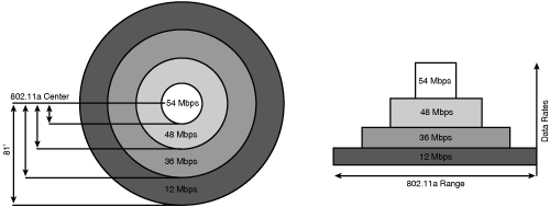
The Cisco Aironet wireless products are considered to be LAN, not WAN, wireless products. They are intended for in-building wireless networks or line-of-sight outdoor bridging applications. No license is required for the spread spectrum and OFDM devices in most countries. They are not designed for a mesh or citywide wireless network. They are not WAN or MAN devices; cellular phones, pagers, or Mobitex; or PCS devices. There are no rental, ongoing, or licensing fees for the use of Cisco Aironet wireless devices. To help clear up any confusion, Figure 18-3 illustrates the coverage areas and data rates of various wireless data networks in use today.
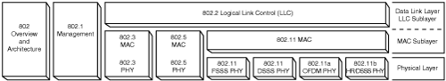
The IEEE 802 committee develops open standards for LANs and WANs. Figure 18-4 provides a layout of the 802 framework. For example, the 802.3 (the standard defining wired Ethernet networks) committee develops standards for Ethernet-based wired networks. The 802.11 (a group of wireless networking standards, also known as Wi-Fi) committee develops standards for WLANs.
In July 1997, the IEEE ratified the 2.4-GHz standard that included DSSS technology, Frequency Hopping Spread Spectrum (FHSS) technology, and infrared light, commonly referred to as IR, at the physical layer. The standard specified 1 Mbps as the standard speed and 2 Mbps as a “turbo” mode. In September 1999, the IEEE 802.11a standard (5 GHz at 54 Mbps) and the IEEE 802.1lb standard (2.4 GHz at 11 Mbps) were ratified by the IEEE. In June 2003, the IEEE ratified the 802.11g standard (2.4 GHz at 54 Mbps). This standard is backward compatible with 802.11b systems because both use the same 2.4-GHz bandwidth.
802.11 is based on the IEEE 802.3 standard. Moreover, 802.3 and 802.11 standards evolved based on bandwidth demands by both applications and the number of users. Ethernet scaled from 10 Mbps (Ethernet or 10BASE-T), 100 Mbps (Fast Ethernet), and 1 Gbps (Gigabit Ethernet) to 10 Gbps. Wireless scaled from 1 and 2 Mbps (802.11), 5.5, and 11 Mbps (802.11b, including 1- and 2-Mbps rates for backward compatibility) to 54 Mbps (802.11a and 802.11g). Both wireless and Ethernet use carrier sense multiple access (CSMA). Ethernet adds collision detection (CD), and wireless uses a modified form of collision avoidance (CA).
Ethernet CSMA/CD is designed to easily detect or sense a collision based on the wire voltage. The wired LAN uses unshielded twisted-pair (UTP) copper cables that have electrical pulses to transmit data back and forth. When two stations transmit simultaneously, the wire voltage is raised, signifying a collision. WLANs are not afforded the same luxury due to the inability to control air waves. Each client or station (an end-user device such as a laptop or PC) must wait for the active station to be done. Once the active station is done, another station wanting to speak announces itself and how long it wants to speak. The station knows its transmission was successful only if it receives an acknowledgement. If two stations transmit data simultaneously, the absence of the positive acknowledgement implies a collision. Both stations then use a backoff algorithm to wait prior to transmitting data again.
All the upper-level services work the same. Without additional tools, the upper-level services such as DHCP and SNMP can take advantage of wireless. The user experience is like being connected to the wired network. Telecommuters can connect to their workplace through a Virtual Private Network (VPN) IPsec tunnel created over a wired or wireless connection. Home users can access the Internet while roaming around.
Remote and wireless users should be authenticated prior to access to an enterprise network. Cisco Secure Access Control Server (ACS) provides a centralized identity networking solution and simplified user management experience across all Cisco devices and security-management applications. Cisco Secure ACS ensures enforcement of assigned policies by allowing network administrators to control authentication, authorization, and accounting (AAA).
A view of the physical (Layer 1) and data link (Layer 2) layers of the OSI model will help you to understand how the 802.11 Physical (PHY) components relate. The PHY components are MAC, Physical Layer Convergence Procedure (PLCP), and the Physical Medium Dependent (PMD). Figure 18-5 breaks down the PHY components.
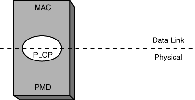
Consider how the data link layer can be broken into the MAC and LLC sublayers. The PHY continues to use the MAC portion while replacing the LLC with the PLCP. The PLCP provides a common interface to the MAC sublayer and is more unique in that it transcends into the physical layer, too. The PLCP creates frames from the MAC layer PDUs (MPDUs) by adding the correct header based on the PMD’s selected modulation. When receiving frames from the PMD, the PLCP header is stripped off and sent to the MPDU of the MAC sublayer. The PMD component is responsible for modulating and transmitting the frames received from the PLCP. It also processes received signals from other transmitters, demodulates them, and sends those frames to the PLCP component.
802.11 uses the same frequency for both transmitting and receiving (half duplex, sometimes called simplex). The bandwidth is shared by all the computers on the wireless network. A WLAN can handle several client stations but can become unusable with too many clients.
Physically, the main difference between wireless and wired networks is, of course, the presence or absence of cables for the communications medium. Wired networks transfer through cables electrical signals that represent information, whereas wireless networks transfer data through the air. WLAN users are able to roam around without getting disconnected from the network while in RF range.
Roaming comes at a cost. A hacker with the right wireless components could wreak havoc on a WLAN. Unlike the physical security with wired LANs, WLANs are open and should always be secured as if they were a publicly accessible network. Preventing hackers from listening to a WLAN is not realistic. The real solution is making your WLAN data indiscernible through power and encryption security services. Too much power creates an easy target due to the signal-to-noise ratio. Too little power causes reachability problems due to the signal-to-noise ratio as well.
Privacy is addressed by 802.11 by an optional service called Wired Equivalent Privacy (WEP). WEP is based on the RC4 algorithm, which the encryption keys must match on both the client and the AP for frame exchanges to succeed. Any diligent hacker can break WEP because it is not a strong encryption method. WEP is analogous to speaking privately in a foreign language. After someone understands that language, the conversation is no longer private. So, simple abuses, such as neighbors leeching onto your Internet access, can be stopped by using WEP, but not much more than that.
Other problems may arise in the WLAN. Knowing the common issues prior to design will help mitigate them. Just as light and sound bounce off objects, so do RF signals. This means that there can be many RF paths from the transmit (Tx) to receive (Rx) antennas. These multiple signals combine to cause distortion of the signal. The higher the number of radios in a cell, the higher the noise level in the cell. Because of multipath reception, the signal strength might be strong, but it might also be distorted. Proximity does not guarantee better performance.
Coverage holes are the voids where the RF signal is not discernable. A perfect survey can get coverage holes if environmental changes are made. Such RF examples would be the addition of plants, office furniture getting moved, or walls getting changed from structural modifications. RF gets absorbed or reflected so that the signal becomes too weak for the station to pick out the signal from the noise. The closer the antennas are to each other, the stronger all paths are, including reflected paths, which increases the possibility of interference from reflected paths. The farther the antennas are from each other, the greater the difference between reflected and direct (primary) signal. So farther distance makes for decreased signal strength but also reduces the strength of any reflected signal.
Environmental factors such as reflections, refractions, and diffractions (all of which can cause multipath interference) can degrade a signal between the transmitter and receiver. Multipath interference can cause high signal strength yet low signal quality, so that the data would be unreadable. One indication that you are experiencing multipath interference is that signal strength and signal quality fluctuate drastically, even when you are moving the client only a little (inches). You can relate this to a common occurrence in your car. As you pull up to a stop sign, you might notice static on the radio. But as you move forward a few inches or feet, the station starts to come in more clearly. By rolling forward, you move the antenna slightly, away from the point where the multipath signals converge.
Interference occurs when another RF source produces a signal on the same channel. If there is severe signal interference in one area, it is possible to change to another channel and totally avoid the interference. Normally, changing channels does not happen automatically in DSSS and must be done with reconfiguration to the AP. Cisco firmware will allow an AP to search for the least-congested channel.
As the data is further compressed, it requires a stronger signal as compared to the noise level. More noise means slower speed for the data to be received correctly. The same is true in radio. As a receiver moves farther from a transmitter, the signal gets weaker, and the difference between the signal and noise decreases. At some point, the signal cannot be distinguished from the noise, and loss of communication occurs. The amount of compression (or modulation type) at which the signal is transmitted determines the amount of signal necessary to be clearly received through the noise. As transmission or modulation schemes (compression) become more complex and the data rate goes up, immunity to noise decreases and coverage goes down. Or, stated simply, when frequency and speeds are increased, the cell coverage distances are decreased.
Mobility is the freedom from constraints such as physical connections (power cords, network cables, and so on). Mobile devices contain client software to manage the WLAN client cards. WLAN client cards can have a significant impact on the battery life of a mobile device. One or two surveys will burn that into your brain. Moreover, using 802.11a drains the battery life faster than 802.11b or 802.11g.
To help reduce the battery drain problem, Cisco client cards use power save mode to preserve battery life while maintaining association. The AP buffers data during power save mode, which reduces the overall throughput.
Different countries have different regulatory bodies and may have as many as 14 channels available. Table 18-1 gives the channel set breakdown on several regulatory domains. In some countries, this might mean that the number of nonoverlapping channels is reduced to one, and an aggregate data rate of 33 Mbps might not be possible.
Table 18-1. 2.4-GHz Regulated Channels Table
Channel Identifier | Center Frequency | Regulatory Domain | |||
|---|---|---|---|---|---|
Americas | Europe, Middle East, and Asia | Japan | Israel | ||
1 | 2412 MHz | ✓ | ✓ | ✓ | |
2 | 2417 MHz | ✓ | ✓ | ✓ | ✓ |
3 | 2422 MHz | ✓ | ✓ | ✓ | ✓ |
4 | 2427 MHz | ✓ | ✓ | ✓ | ✓ |
5 | 2432 MHz | ✓ | ✓ | ✓ | ✓ |
6 | 2437 MHz | ✓ | ✓ | ✓ | ✓ |
7 | 2442 MHz | ✓ | ✓ | ✓ | ✓ |
8 | 2447 MHz | ✓ | ✓ | ✓ | ✓ |
9 | 2452 MHz | ✓ | ✓ | ✓ | ✓ |
10 | 2457 MHz | ✓ | ✓ | ✓ | |
11 | 2462 MHz | ✓ | ✓ | ✓ | |
12 | 2467 MHz | ✓ | ✓ | ||
13 | 2472 MHz | ✓ | ✓ | ||
14 | 2484 MHz | ✓ | |||
There are 11 channels available in the United States; however, only three of these channels (1, 6, and 11) are nonoverlapping. In the European Telecommunications Standards Institute (ETSI) domains, there are 13 available channels, but again there are only three nonoverlapping channels. In Japan, there is an additional channel located at the top end of the band. It is possible to use this along with three other channels for a total of four nonoverlapping channels.
The wireless connection can be as simple as two wireless laptops or two PCs equipped with wireless adapter cards. A wireless connection requires little to no setup for the WLAN to work. This connection type is used when transferring information directly between stations as long as they remain within radio range. Cisco does not consider this to be a WLAN.
Clients refers to end-user hardware such as PCs, laptops, and personal digital assistants (PDAs). WLAN client adapter cards can enable stations to have network and Internet access anywhere within a building that is equipped with a wireless network infrastructure. Client adapters can connect to a wireless network in either ad hoc (peer-to-peer) mode or infrastructure mode using APs. The following list describes the two WLAN client adapters:
Cisco Aironet 802.11a/b/g CardBus Wireless LAN Client Adapter—. This 802.11a/b/g-compliant CardBus client adapter is ideal for laptops and tablet PCs and complements the 1100 and 1200 Series APs.
Cisco Aironet 802.11a/b/g PCI Wireless LAN Client Adapter—. This 802.11a/b/g-compliant low-profile PCI client adapter is ideal for slim desktop and point-of-sale devices and complements the 1100 and 1200 Series APs.
The APs themselves can be put in either one of Cisco’s two WLAN architectures: Autonomous and Lightweight. Autonomous APs were once called thick, fat, or decentralized, and lightweight APs were called thin or centralized.
Both autonomous and lightweight APs use the network infrastructure, which may require additional design considerations to support the WLAN. Various switches, routers, and VPN concentrators may be needed. Network services such as AAA, certificate authority (CA), DHCP, and DNS can be valuable for security reasons.
An autonomous AP has local configurations requiring local management (for example, Telnet to each device to add an infrastructure SSID), which might make consistent configurations difficult and add to the cost of network management. The following APs are autonomous:
1100 Series—. An affordable, easy-to-install, single-band AP.
1130 Series—. An all-in-one dual-band 802.11a/b/g AP that has all the radios and antennas included.
1200 Series—. A dual-band 802.11a/b/g AP; was the first versatile enterprise-class AP.
1230AG Series—. A dual-band 802.11a/b/g AP designed for harsh WLAN environments or installations that require specialized antennas. It includes hardware encryption.
1240AG Series—. IEEE 802.11a/b/g access, second-generation, versatile AP.
A lightweight AP receives control and configuration from a WLAN controller to which it is associated. This reduces the security concern of a stolen AP and provides a single point of management. The Cisco Aironet 1000 Series Lightweight AP is an 802.11a/b/g dual-band device. The following autonomous APs are lightweight capable:
1130 Series Lightweight—. An all-in-one dual-band 802.11a/b/g AP
1200 Series Lightweight—. A single-band lightweight AP
1240AG Series Lightweight—. A dual-band 802.11a/b/g AP
The lightweight Wireless LAN Controllers communicate with Cisco 1000 Series or lightweight-capable APs over any Layer 2 (Ethernet) or Layer 3 (IP) infrastructure using the Lightweight Access Point Protocol (LWAPP). These devices support automation of numerous WLAN configuration and management functions. Wireless LAN Controllers are responsible for centralized system-wide WLAN management functions, such as security policies, intrusion prevention, RF management, quality of service (QoS), and mobility. Stated simply, this is where the instructions are processed. They work in conjunction with Cisco 1000 Series Lightweight APs and the Cisco Wireless Control System (WCS) to support business-critical wireless applications. Cisco wireless LAN controllers provide the control, scalability, security, and reliability that network managers need to build secure, enterprise-scale wireless networks—from branch offices to main campuses.
Cisco Systems currently offers the following controllers:
2000 Series—. Can handle up to six lightweight APs. Ideal for smaller enterprises.
4400 Series—. Can handle up to 100 lightweight APs. Ideal for large enterprises.
4100 Series—. Can handle up to 36 lightweight APs. An Enhanced Security Module (ESM) is available to offload processor-intensive security options. Ideal for medium enterprises.
Catalyst 6500 Series Wireless Services Module (WiSM)—. Ideal for medium to large enterprises with clustering capabilities.
Wireless LAN Controller Module (WLCM) for Cisco Integrated Services Routers (ISR)—. Ideal for small to medium businesses and enterprise branch offices.
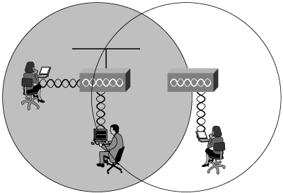
Wireless networks have two main categories: WLANs (in-building or mesh), and wireless bridges (building-to-building). Figure 18-6 illustrates two WLAN users connecting locally with a wireless bridge connection to the remote building.
WLANs replace the Layer 1 transmission medium of a traditional wired network (usually Category 5 cable) with radio transmission over the air. WLANs can plug into a wired network and function as an overlay to traditional or wired LANs, or they can be deployed as a standalone LAN where wired networking is not feasible. WLANs permit the use of desktop or portable computers or specialty devices in a system where connection to the network is essential. A computer with a wireless network interface card (NIC) can connect to the wired LAN through the AP. WLANs are typically located within a building and are used for distances up to 1000 feet. Properly deployed WLANs can provide instant access to the network from anywhere in a facility. Users can roam without losing network connection.
Mesh networks are scalable outdoor networks that continuously communicate with each other to determine link paths. If a link is degraded, the AP will determine whether a better path exists and will route traffic through a more optimal node.
Intelligent wireless routing is provided by the patent-pending Adaptive Wireless Path (AWP) protocol. This enables each AP to identify its neighbors and intelligently choose the optimal path to the wired network by calculating the cost of each path in terms of signal strength and the number of hops required to get to a controller.
The Cisco Aironet 1500 Series Lightweight Outdoor Mesh AP operates with Cisco wireless LAN controllers and Cisco WCS software. The AP dedicates the 5-GHz radio frequency for backhaul operations to reach a wired network and uses the 2.4-GHz radio frequency for wireless clients.
Wireless bridges allow two or more networks that are physically separated to be connected on one LAN, without the time or expense of dedicated cable or T1 lines.
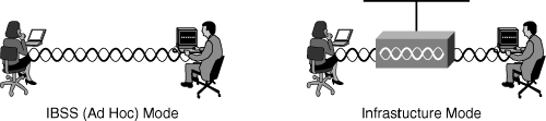
WLAN designs build upon the components of wireless. Basic Service Sets (BSSs) are the building block modes used to design wireless network solutions. The BSS is where mobile clients use a single AP for connectivity to each other or wired network resources. The Extended Services Set (ESS) is two or more BSSs connected by the distribution system. Independent (ad hoc) mode and infrastructure mode are the two BSS modes.
Note
Many clients default to ad hoc mode, which has a negative impact on infrastructure WLAN in regard to both bandwidth usage and network security.
Independent mode, also known as ad hoc mode, is a peer-to-peer network where mobile clients connect directly without an intermediate AP, sharing files between two or more mobile clients directly. This mode is called an Independent Basic Service Set (IBSS).
Infrastructure mode adds greater diversity and control for larger environments. Infrastructure mode incorporates APs, which are used to provide stations with communication.
Figure 18-7 illustrates both BSS modes. The left side is a simple peer-to-peer connection, and the right side is a typical infrastructure WLAN.
In BSS infrastructure mode, the AP attaches to the Ethernet backbone and communicates with all the wireless devices in the cell area. The AP is the master for the cell and controls traffic flow to and from the network. The remote devices do not communicate directly with each other; they communicate with the AP.
An aspect of the BSS is the basic service area (BSA), which is the cell area of RF coverage provided by an AP, also referred to as a microcell.
To extend the BSA, or to simply add wireless devices and extend the range of an existing wired system, an AP can be added. (As the name access point indicates, this unit is the point at which wireless clients can access the network.)
If a single cell does not provide enough coverage, any number of cells can be added to extend the range. This is known as an extended service area (ESA). It is recommended that the ESA cells have 10 to 15 percent overlap to allow remote users to roam without losing RF connections. Bordering cells should be set to different nonoverlapping channels for best performance.
In an environment where extended coverage is needed but access to the backbone is not practical or available, a wireless repeater can be used (see Figure 18-8). A wireless repeater is simply an AP that is not connected to the wired backbone. This requires a 50 percent overlap of the AP on the backbone and the wireless repeater. Receive and retransmit times involved will decrease because of data rates. The repeater must be on the same channel as the root (the AP connected to Ethernet).
A wireless bridge can act as an AP in some applications by communicating with clients at the remote sites. This is accomplished with a Cisco Work Group Bridge (WGB), such as shown in Figure 18-9. The WGB allows up to eight wired machines to be attached to the same radio device. The WGB is ideal for connecting remote workgroups to a wired LAN and provides a single MAC address connection into an AP and onto the LAN backbone. The WGB cannot be used in a peer-to-peer mode connection and must communicate to an AP or a bridge in AP mode. The WGB has an 802.11b radio that communicates with Cisco Aironet APs and bridges with 802.11b or 802.11g radios.
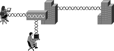
Bridges such as the Cisco 1300 and 1400 Series are used to connect two or more wired LANs, usually located within separate buildings, to create one large LAN. Cisco Aironet bridges operate at the MAC address layer (data link layer), which means they have no routing capabilities. A router must be put in place if IP subnetting is needed within the network.
The Cisco 1300 and 1400 Series Wireless Bridges are designed to be mounted outdoors, typically on a tower or a tall building. Choosing a good mounting location for the bridge is important because it affects the reliability of the wireless link and the maximum data rates that it can support. The most important considerations are distance between bridges and clearance from obstacles. The mounting location can be the top or side of a building, in a window, on a tower or mast providing a clear unobstructed line of sight to the remote bridges, or any suitable flat surface.
Bridging has quickly become one of the most popular uses of wireless networks. This development is in part due to the ease of installation and setup. But it is also due to the variety of emerging markets where WLAN bridging can be applied.
The Root setting is normally used for the “main” side of the bridge. This bridge provides connectivity to the main LAN for other wireless clients or wired clients that are being connected wirelessly. Only one bridge in a WLAN can be set as the root bridge. This is the default setting for Cisco bridges.
In root mode, the bridge supports the following by default:
Non-root bridges—. Typically considered the remote side of the bridge connection
Wireless client cards—. PC card, PCI card end-user connections
WGB—. A bridge that can directly connect wired devices
Repeater—. An AP that helps extend the reachability
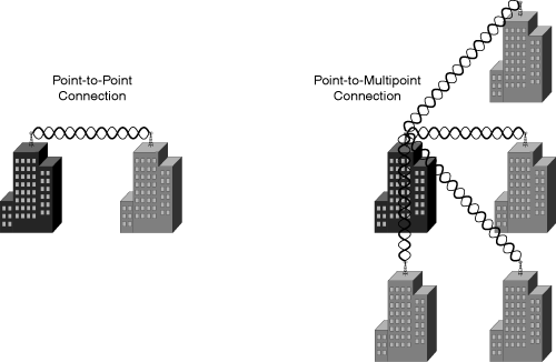
Bridges offer many advantages over other, more costly alternative connections such as T1 lines, cabling, and microwave connections. A bridge can be used in point-to-point or point-to-multipoint connections. Regardless of the connection type, there can be only one root bridge, as shown in Figure 18-10. Figure 18-10 has the point-to-point connection on the left with the root bridge on top of the black building and the non-root bridge on top of the gray building. Moreover, it has the point-to-multipoint connection on the right with a black building (root bridge) and multiple gray buildings (non-root bridges).
A T1 line typically costs from $200 to more than $1000 per month. For a site with four buildings, the cost could be anywhere from $10,000 to $36,000 per year. If such sites were connected via local bridges, the payback for the hardware costs incurred could actually be realized in less than a single year. The hardware cost for wireless bridging can range from $1000 to $10,000, depending on the design configuration.
Another popular option for smaller businesses might be a cable or DSL modem. This solution sometimes offers faster download speeds but slower upload speeds. Reliability is often an issue. Cable users are often forced to “share” connections with other nearby businesses, sometimes causing a sacrifice in speed.
Microwave is a solution for some sites where distance is short, reliability is not critical, and money is not an issue. With licensed microwave, a U.S. Federal Communications Commission (FCC) license is required. The cost of the equipment is typically more than $10,000 per site, not including installation items. In heavy fog, rain, or snow, performance is questionable. Multipoint connections are usually not possible.
An enterprise WLAN consists of tens or hundreds of APs covering floors, buildings, and whole campuses too. Each AP microcell is carefully designed. Figure 18-11 illustrates microcells with laptop computers and pen-based computers. The WLAN can include printers and any other devices that are found on typical wired networks.
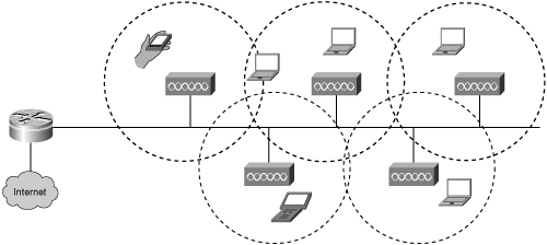
The user has the ability to move freely anywhere the microcells permit.
The following are the benefits of a microcell architecture:
Seamless roaming—. Roaming across APs allows users to maintain connection while moving around a facility or campus environment.
Power management—. Managing the radio results in better battery life for portable devices.
Dynamic load balancing—. Users can be dynamically distributed among APs to increase the throughput of each user.
Fault tolerance—. WLAN backbones can be provided with the use of APs with overlapping coverage cells.
Radio frequencies are high-frequency, alternating current (AC) signals that are radiated into the air via an antenna, creating radio waves. Radio waves propagate away from the antenna in a straight line in all directions at once just like “light” from a light bulb. Just as spreading more light bulbs around the room provides better overall lighting, spreading more antennas around a service area provides a stronger average signal for mobile clients.
When radio waves hit a wall, door, or any obstruction, there is attenuation of the signal, which weakens the signal and may reduce throughput.
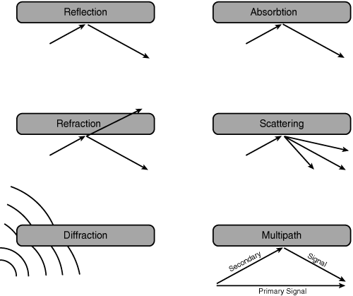
Several natural causes impact radio waves/RF:
Reflection—. Occurs when RF bounces off objects (such as metal or glass surfaces).
Refraction—. Occurs when RF passes through objects and changes direction (such as glass surfaces).
Absorption—. Occurs when RF is absorbed by an object (such as a wall or furniture).
Scattering—. Occurs when an RF wave strikes an uneven surface and is reflected in many directions. Also occurs when an RF wave travels through a medium that consists of objects that are much smaller than the wavelength of the signal (such as heavy dust).
Diffraction—. Occurs when an RF wave strikes sharp edges (such as external corners of buildings), which bends the signal.
RF wave propagation naturally encounters the attenuation factors in the preceding list, all of which need to be considered when designing, implementing, and troubleshooting WLANs. Figure 18-12 represents each RF impact.
Note
Reflection may cause signal gain, and if increased power is not required, an AP’s power can be reduced.
Some form of absorption occurs with almost all materials, which reduces the overall signal strength.
Multipath interference is less of an issue when using an OFDM technology because multipath is frequency selective. DSSS comprises a single signal, whereas OFDM comprises multiple signals. While multipath interference affects an entire DSSS signal, it affects only a subset of the OFDM signals.
Cisco 1000 series APs address multipath interference issues by providing multiple antennas that support diversity for the 802.11b band. Even with multiple antennas, multipath interference can occur.
WLANs transmit power just like radio stations do to reach listeners. The power levels for wireless are in milliwatts, whereas the power levels for radio stations are in megawatts.
Here are some units of measure to help you better understand the RF math:
dB (decibel)—. The difference or ratio between two signal levels. Used to measure relative gains or losses in an RF system. Named after Alexander Graham Bell and used to describe the effect of system devices on signal strength.
dBm (decibels per milliwatt)—. A signal strength or power level. Zero dBm is defined as 1 mW of power into a terminating load such as an antenna or power meter. Small signals are negative numbers (such as –83 dBm).
dBW (decibels per watt)—. A signal strength or power level compared to 1 watt (0 dBw = 1W). One ampere (1A) of current at one volt (1V).
dBi (isotropic)—. The gain a given antenna has over a theoretical isotropic (point source) antenna. Unfortunately, an isotropic antenna cannot be made in the real world, but it is useful for calculating theoretical fade and system operating margins.
The math formula used in WLANs is too complex for most people to solve without a calculator. The formula requires adding gains or losses, described in decibels, and then converting those results into an absolute power, described in milliwatts or watts.
The formula is
Transmit Power (dBm) = 10 * log[Transmit Power (mW)]
You can easily see, using Table 18-2, how the gains and losses relate to power levels. Refer to this table to help out whenever needed.
RF math can be made easier by understanding a few key points:
Every 3 dB will double when gaining (gain) or decrease by half when losing (loss).
Every 10 dB will increase by a factor of 10 when gaining (gain) or decrease by a factor of 10 when losing (loss).
Add all the gains and losses to come up with the end result and convert.
A 9-dB loss can be broken down into –3 dB + –3 dB + –3 dB. A signal level of 200 mW will be decreased to 25 mW. It can be broken down as follows:
200 mW + –3 dB = 100 mW
100 mW + –3 dB = 50 mW
50 mW + –3 dB = 25 mW
25 mW is the end result
Gain increases the RF signal amplitude. Two common sources for gain are amplifiers and antennas.
Loss is a decrease in the RF signal strength. Losses impact the WLAN design and are part of our everyday world. All the cables and connections between the AP and the antenna cause loss. Losses are the real concern, and the common causes of loss are distance, resistance of cables and connectors, mismatched impedance in cables and connectors, and objects such as the following in the path of a signal that absorb or reflect RF signals:
Fixed walls: 3.0 dB
Movable walls: 1.4 dB
Doors: 2.0 dB
Metal partitions: 5.0 dB
Windows: 2.0 dB
Exterior walls: 10.0 dB
Basement walls: 20.0 dB
Antennas used in WLANs come in many shapes and sizes based on the differing RF characteristics desired. The physical dimension of an antenna is directly related to the frequency at which the antenna transmits or receives radio waves. As the gain increases, the coverage area becomes more focused. High-gain antennas offer longer coverage areas than low-gain antennas at the same input power level. As frequency increases, the wavelength and the antennas become smaller.
Antennas can be categorized into one of three types:
Omnidirectional—. The most widely used today but not always the best solution. The shape of the radiant energy is a doughnut-shaped pattern.
Semidirectional—. Offer the ability to direct and apply gain to the signal. The shape of the radiant energy is a cowbell-shaped pattern.
Highly directional—. Intended for highly directed signals that must travel a long distance. The shape of the radiant energy is a telescope pattern.
Note
Reducing power or applying different antennas is not a security option. Even if you direct the signal away from vulnerable spots, a high-gain receiver may still be able to pick up the signal.
Note
The Cisco 1000 Series AP can be configured to provide semidirectional capability by disabling one internal antenna or connecting an external antenna. An external antenna can be used to solve the problem of providing outside coverage areas, because the Cisco 1000 Series AP is designed only for indoor use.
Designing the right WLAN solution requires using the right antenna. Table 18-3 provides a helpful generic guide to antenna selection. Each antenna type is included with its ranges for both gain and EIRP. Reviewing the manufacturers’ antenna specifications provides the specific details.
Table 18-3. Antenna Selection Guide
Antenna Type | Application | Gain | EIRP Ranges | |
|---|---|---|---|---|
Azimuth | Elevation | |||
Omnidirectional | Indoor/outdoor: open spaces and office cubicles | 2–5 dBi | 360° | 25–75° |
Semidirectional | Indoor/outdoor: longer hallways with offices and warehouse isles | 6–13 dBi | 60–80° | 50–70° |
Highly directional | Outdoor: between buildings | 14–21 dBi | 30–55° | 50–70° |
Omnidirectional antennas have the following characteristics:
Radiate equally in all directions around their axis.
Most common antenna used in WLANs, APs, and Personal Computer Memory Card International Association (PCMCIA) cards. This antenna is frequently used in open space or larger cubicle areas.
The shape of the radiant energy is that of a doughnut or bagel.
The higher the gain of the antenna, the more the doughnut gets squeezed flat.
Semidirectional antennas have the following characteristics:
Direct the energy more in one particular direction.
In WLANs, Yagi antennas are frequently used semidirectional antennas.
Very effective in directing signal into hard-to-reach locations such as long hallways or distant corners.
Highly directional antennas have the following characteristics:
Radiate equally in all directions around their axis.
Emit a very narrow beam and long distance.
Typically concave, dish-shaped devices.
Ideal for long-distance, point-to-point applications such as communications between buildings.
Achieve distance with a very narrow signal.
Antenna diversity refers to the condition under which multiple antennas are receiving signals from a single source and the AP’s ability to respond using the best antenna. Antenna diversity reduces multipath issues.
Note
A Cisco Airespace AP will not support an external antenna and an internal antenna simultaneously. When the external antenna is enabled, the software will disable the internal antenna.
Caution
You should not enable an external antenna without having an external antenna physically attached to the AP, because doing so may damage the radio.
The most commonly used antenna connectors are male connectors with reverse-polarity TNC jacks (RP-TNC connectors). It is the same connector type that Cisco uses on its APs.
Cisco Airespace APs are certified for any external 2.4-GHz or 5-GHz patch antenna with 6-dBi gain or less.
Wireless is the result of organizational standards and regulatory guidelines. With hundreds of countries around the world, it is a welcome relief to have organizations and consortiums providing standards and guidelines.
Some of the wireless regulatory agencies and standards are as follows:
IEEE—. Institute of Electrical and Electronic Engineers (http://www.ieee.org) creates and maintains operational standards.
ETSI—. European Telecommunications Standards Institute (http://www.etsi.org) is chartered to produce common standards in Europe.
Wi-Fi Alliance—. Wi-Fi Alliance (http://www.wi-fi.com) promotes and tests for WLAN interoperability.
WLANA—. Wireless LAN Association (http://www.wlana.org) educates and raises consumer awareness regarding WLANs.
In the United States, the Federal Communications Commission (FCC) does the following:
Regulates the use of wireless devices in the United States. The FCC established the rules limiting the frequencies that wireless bands can use and the output power for the bands.
Specifies that WLANs can use the license-free ISM bands. The ISM bands start at 902 MHz, 2.4 GHz, and 5.8 GHz. ISM bands vary in width from 26 MHz to 150 MHz.
Specifies that WLANs can use three UNII bands. UNII bands are at 5 GHz and are 100-MHz wide. Moreover, they are intended for indoor (lower band), indoor/outdoor (middle band), and outdoor (upper band) uses. All are currently being used for indoor use today.
The IEEE has made an extensive effort to create open standards. The following IEEE 802.11 standards exist today:
802.11a—. 5 GHz, ratified in 1999
802.11b—. 11 Mbps, 2.4 GHz, ratified in 1999
802.11d—. World mode, ratified in 2001
802.11e—. Quality of service, ratified in 2005
802.11F—. Inter-Access Point Protocol (IAPP), withdrawn in 2006
802.11g—. Higher data rate (>20 Mbps) 2.4 Mbps, ratified in 2003
802.11h—. Dynamic Frequency Selection and Transmit Power Control mechanisms, ratified in 2003
802.11i—. Authentication and security, ratified in 2005
802.11j—. Additional Japanese frequencies, ratified in 2005
802.11k—. Radio resource management draft, planned to be ratified in 2007
802.11n—. High throughput draft, planned to be ratified in 2007
The 802.11a, b, and g specifications all relate to WLAN physical layer standards.
Cisco APs currently support the 802.11d standard for world mode. World mode enables the AP to inform an 802.11d client device which radio setting the device should use to conform to local regulations.
The IEEE 802.11e standard is being developed to enhance the current 802.11 MAC to expand support for applications with QoS requirements and improve the capabilities and efficiency of the protocol. This standard will assist with voice, video, and other time-sensitive applications.
The IEEE 802.11F standard was a recommended practice guideline, defining a protocol for intercommunication between APs, to assist in roaming and handoff of traffic. The IEEE administratively withdrew 802.11F in February 2006. Most vendors have implemented their own proprietary IAPP for use with their own APs.
The IEEE 802.11h standard is supplementary to the MAC layer to comply with European regulations for 5-GHz WLANs. Most European radio regulations for the 5-GHz band require products to have Transmission Power Control (TPC) and Dynamic Frequency Selection (DFS). TPC limits the transmitted power to the minimum needed to reach the farthest user. DFS selects the radio channel at the AP to minimize interference with other systems, particularly radar.
The IEEE 802.11i standard is intended to enhance the current 802.11 MAC to provide improvements in security.
The IEEE 802.11j standard is intended to enhance the 802.11 standard and amendments, to add channel selection for 4.9 GHz and 5 GHz in Japan to conform to Japanese rules on operational mode, operational rate, radiated power, spurious emissions, and channel sense.
The IEEE 802.11k task group was developed to define and expose radio and network information as well as facilitate the management and maintenance of a wireless and mobile LAN. It is also expected to enable new applications based on this radio information—for example, location-enabled services.
The IEEE 802.11n task group was created to improve the WLAN user experience by providing significantly higher throughput of at least 200+ Mbps over the air, 100 Mbps measured at the MAC data service AP. Changes to the PHY/MAC functionality helped to increase the bandwidth. More issues need to be resolved, such as the use of Multiple Input, Multiple Output (MIMO) antennas and getting 40-MHz channels approved. Designing WLAN solutions based on draft standards is not a best practice.
2.4-GHz 802.11b/g has three nonoverlapping channels. This means that three APs could operate in the same cell area without sharing the media. An AP on channel 1 does not share time with an AP on channel 6, because they do not have common frequencies. There is no degradation in throughput when three APs are in the same cell area if the APs are each on a nonoverlapping channel. Three APs in the same cell using three non-overlapping channels provide an aggregated data rate of 33 Mbps with an aggregated throughput of 18.6 Mbps. If the same three APs shared the same channel, the aggregate data rate would still be 33 Mbps with the aggregated throughput of 7 Mbps.
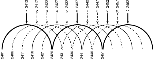
All channels are known by their center frequency, and they are as follows: 1 (2412); 2 (2417); 3 (2422); 4 (2427); 5 (2432); 6 (2437); 7 (2442); 8 (2447); 9 (2452); 10 (2457); 11 (2462); 12 (2467); and 13 (2472). The top part of Figure 18-13 illustrates this information along with the starting frequency on the bottom.
The 802.11g standard was ratified in June 2003. It operates in the same 2.4-GHz band as 802.11b and uses the same three nonoverlapping channels. Moreover, there is full backward compatibility with 802.11b.
The 802.11g specification uses Orthogonal Frequency Division Multiplexing (OFDM) modulation for 802.11g data rates and Complementary Code Keying (CCK) modulation for 802.11b data rates.
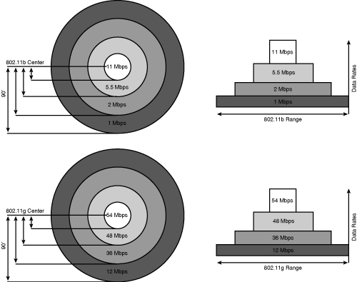
The 802.11g data rates are 54, 48, 36, 24, 18, 12, 9, and 6 Mbps. The 802.11b data rates are 11, 5.5, 2, and 1 Mbps. The 2.4-GHz channels are 22-MHz wide. Figure 18-14 provides a comparison of the 2.4-GHz common data rates and ranges.
The relationships between data rates and distance for 802.11g are similar to 802.11b, but the data rates themselves are higher. The difference between 802.11b and 802.11g is how the data is transmitted over the airwaves, not in the antennas or radios themselves. One radio handles both protocols but not simultaneously.
Note
It requires greater signal-to-noise ratio to receive a signal with more complex modulation. Higher data rates require more complex modulation than lower dates rates. Therefore, higher data rates can only be received at shorter distances because signal strength decreases with distance while the noise floor stays constant. At greater distances, the signal-to-noise ratio is lower than at shorter distances.
Different countries allow different channels and allow different amounts of transmit power.
Part of the 802.11g protocol design ensures 802.11b backward compatibility by detecting and supporting those clients who end up reducing the 802.11g throughput.
Protection mode or mixed mode is enabled when an 802.11b client associates to an 802.11g AP. Additionally, it can be enabled by another 802.11g that can hear the beacons from another 802.11g AP having an 802.11b client associated. The Non-ERP Present bit is set by an 802.11g AP when it has an 802.11b client associated to it. The Use Protection bit is set when an 802.11g AP hears a beacon with the Non-ERP Present bit set on the same channel as it is operating or it has an 802.11b client associated.
With protection, broadcasts must support 802.11b clients as well as the fact that an 802.11b client will transmit at slower data rates than an 802.11g client. Mixed environments will generally have a maximum of 18 Mbps independent of frame transmission rate for the 802.11g devices. 802.11g-only environments can obtain rates over 20 Mbps.
802.11a-compliant devices operate in the 5-GHz UNII band. 802.11a and 802.11b are not compatible due to differences in frequencies. 802.11a requires a different radio and antenna.
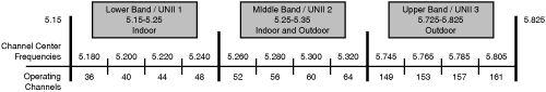
The 5-GHz UNII band is made up of three separate 100-MHz-wide bands known as the lower, middle, and upper bands. Within each of these three bands are four nonoverlapping channels. The FCC specifies that the lower bands be used indoors, the middle bands indoors/outdoors, and the upper bands outdoors.
The channels and center frequencies are as follows: 36 (5.180); 40 (5.200); 44 (5.220); 48 (5.240); 52 (5.260); 56 (5.280); 60 (5.300); 64 (5.320); 149 (5.745); 153 (5.765); 157 (5.785); and 161 (5.805). Figure 18-15 illustrates the channels in the UNII bands.
The capability to use 4, 8, or 12 nonoverlapping channels is an improvement. However, this improvement depends on the vendor’s implementation and the country-specific regulations. Having additional nonoverlapping channels is an advantage when implementing an enterprise WLAN solution. The additional channels are an advantage when dense, high-bandwidth requirements are needed.
Pico cells solve the high-density and bandwidth-requirement issues and are used in places such as stock exchanges and trading floors. Smaller than microcells and solution specific, the use of pico cells needs to be discussed first with the manufacturer’s sales team due to solution-specific configuration/supplicant.
OFDM modulation technology is less susceptible to noise and multipath issues when compared to DSSS. OFDM is a more efficient modulation technique that enables the high data rates of 6, 9, 12, 18, 24, 36, 48, and 54 Mbps. Figure 18-16 shows the 802.11a common data rates.
Understanding the advantages and disadvantages of each standard helps in knowing which one to choose.
802.11a provides the better throughput because it does not deal with any backward-compatibility issues. 802.11a has more channels, which provides less overall interference. Fewer APs will be operating on the same channel.
802.11g gives most organizations an easy migration plan and backward compatibility with 802.11b. The roaming distance is greater than 802.11b, resulting in fewer APs being deployed.
Antenna selection is much greater with 802.11g than with 802.11a. Moreover, most countries support 802.11g, allowing world mode functionality. The regulatory issues with 802.11a are more complicated outside the United States.
Note
There are benefits and drawbacks of operating with unlicensed frequency. Unlicensed bands are flexible and can be used without significant regulatory overhead. However, other unlicensed devices might use the same frequency, such as 2.4-GHz cordless phones, baby monitors, Bluetooth devices, and microwave ovens, to name a few.
Learning the fundamental concepts and the physical and technological components is required prior to implementing WLANs. How can anything be accomplished without first understanding it?
The implementation of WLANs will draw on all the prior concepts, such as what components are used in a given indoor or outdoor situation. The basics teach us how to ask greater solution-oriented questions about the implementation. Implementing WLANs generically addresses the channel limitation, users versus bandwidth, signaling, and power issues.
802.11b/g networks require a well-thought-out plan. A channel reuse plan is required because only three nonoverlapping channels exist. Those channels are 1 (2412 MHz), 6 (2437 MHz), and 11 (2462 MHz).
Channel reuse eliminates microcell overlapping. You can correlate this concept to the placement of FM radio stations throughout the country. You will never find two radio stations in the same geographic area on the same channel. The same concept holds true for channels and cells. Figure 18-17 helps to depict this concept.

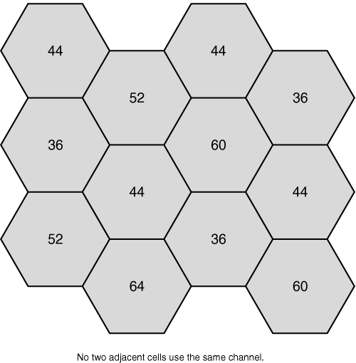
802.11a cells are easier to deploy because there are 12 different channels. These 12 nonoverlapping channels can provide a simpler channel reuse schema, as illustrated in Figure 18-18. Due to the size of the microcell, there are more cells on a per-area basis as compared to 802.11b/g.
It is recommended that neighboring cells not be placed on neighboring frequencies. Two other key points to keep in mind are as follows:
Seven users per AP with no conference rooms provides 4.5 Mbps per user.
Seven users plus one conference room (10 users), which equals 17 total users, provides 1.8 Mbps per user.
The best practices for bandwidth in an 802.11a/b/g WLAN are based on the number of users. The bandwidth requirements are different for 802.11a, 802.11b, and 802.11g because applications require more bandwidth at higher frequencies. The wireless best practices for cell bandwidth are broken down into the three IEEE standards.
The following are the 2.4-GHz 802.11b bandwidth calculations:
25 users per cell—. General office maximum users limited by bandwidth.
Peak true throughput 6.8 Mbps—. 6.8 Mbps × 1024/25 = 278.5 kbps per user.
Cell density—. Maximum number of users per cell. Cell size and maximum data rates.
The following are the 2.4-GHz 802.11g bandwidth calculations:
20 users per cell—. General office maximum users limited by bandwidth.
Peak true throughput 32 Mbps—. 32 Mbps × 1024/20 = 1683 kbps per user.
Cell density—. Maximum number of users per cell. Cell size and maximum data rates.
The 5-GHz 802.11a bandwidth calculations follow:
15 users per cell—. General office users limited by coverage, not bandwidth.
Peak true throughput 32 Mbps—. 32 Mbps × 1024/15 = 2188 kbps per user.
Root bridge is the setting that is normally used for the “main” bridge that is connected to the main network. This bridge provides connectivity to the main LAN for other wireless clients or wired clients that are being connected wirelessly.
In this mode, the bridge supports the following types by default:
Non-root bridges
Wireless client cards (PC card, PCI card)
Work Group Bridges (WGBs)
Access points configured as repeaters
Only one bridge in a WLAN can be set as the root bridge. This is the default setting for Cisco Aironet bridges.
For two or more Cisco wireless bridges to communicate, you must configure one bridge to root bridge mode and the rest of the bridges to non-root mode. The function of a non-root bridge is to actively seek out a radio connection to the root bridge. This must occur before data can be transferred or bridged across a link. Recalling Figure 18-10, the black buildings were the root bridge, whereas the gray buildings were non-root bridges.
The characteristics of a root bridge (parent) are as follows:
Accepts associations and communicates with non-root bridge (child) devices
Will not communicate with other root bridge devices
Communicates with multiple non-root bridges
The characteristics of a non-root bridge (child) are as follows:
Can associate and communicate with root devices or clients
Will not communicate with other root bridge devices
Will communicate with other non-root devices, provided the other non-root devices are communicating with a root
A single parent bridge can support numerous child bridges. The number of child bridges that should be attached to a parent bridge is determined by usage and throughput needs. There is only one exception—a non-root bridge communicates with another non-root bridge as long as one of the non-root bridges has a root bridge in its uplink.
This setting is normally used for a bridge that is used to connect a remote wired LAN and will only communicate with another root bridge. In this mode, the bridge will refuse associations from wireless clients.
One of the most important concepts in installing bridges is line of sight. Wireless bridges are unlicensed devices and are not designed to penetrate objects such as mountains, trees, or buildings. The signal will be either absorbed or reflected, and the end result will be that the bridges will be unable to connect. If there are trees between the bridges, much of the signal will be absorbed.
For a typical 6-foot (183-cm) person, the horizon appears at about 6 miles (9.7 km). Its disappearance is determined by the height of the observer. If you have two 10-foot (305-cm) structures, the top of one will have a line of sight to the other at about 16 miles (26 km), but it will have minimum clearance at the horizon point.
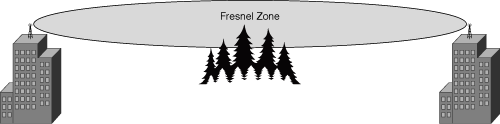
The Fresnel zone is an elliptical area immediately surrounding the visual path. It varies depending on the length of the signal path and the frequency of the signal. Figure 18-19 illustrates a simple Fresnel zone between two buildings. The Fresnel zone can be calculated, and it must be taken into account when designing a wireless link. If the Fresnel zone is obstructed, then the line of sight is not clear and the link might be unreliable.
Inline power, or Power-over-Ethernet (PoE), provides source operating current from the Ethernet port, over the Category 5 cable. It is line power configuration compliant with all Cisco line power–enabled devices. Switches and line power patch panels can reach distances up to 100 meters.
To decrease the cost and complexity of the installation, the Cisco APs can be powered over an Ethernet cable, eliminating the need to run expensive AC power to remote AP installation locations.
For 802.11b-only configurations, line power–enabled devices such as switches and patch panels may be used instead of power injectors. Remember that the standard Cat 5 cable requirements still apply (maximum 328 feet or 100 meters).
Inline power further reduces installation costs, because an electrician is not required. Anyone qualified to run Cat 5 cable can install the cabling required to power Cisco Aironet APs.
Note
Cisco Aironet Power Injector products are designed for use with Aironet 350, 1100, and 1200 Series APs and bridges only.
Cisco Aironet Power Injector products increase the deployment flexibility of Cisco Aironet wireless APs and bridges by providing an alternative powering option to local power, inline power–capable multiport switches, and multiport power patch panels.
An end-span device is a unit that has PoE integrated and thus does not require a midspan device. A midspan device is a standalone unit that adds the PoE capability to existing networking equipment. The unit is inserted into the LAN between the Ethernet switch and the peripherals.
Note
Some midspan devices (such as power injectors), although 802.3af compliant, provide only Class 1 or 2 power and will not adequately power the Cisco Airespace AP. See Table 18-4 for a summary of class power.
The power injector for Cisco Aironet 1100 and 1200 Series APs works with the power supply provided with the AP.
The Power Injector Media Converter converts fiber media to Category 5 media and combines the resulting data signal with power for delivery to the AP or bridge. The power injector media converter accepts 48-VDC power from either the barrel connector of the local power supply or an alternative 48-VDC power source. When powered by an alternate 48-VDC power source connected using the provided power supply pigtail, the Power Injector Media Converter is UL2043 certified and suitable for installation in environmental air spaces. The local power supply is provided with the Cisco Aironet 1100 and 1200 Series APs.
The IEEE 802.3af power specification created a standard for powering devices over copper wire. Table 18-4 provides the classes defined along with the default setting.
The Cisco Airespace AP is a Class 3 device with an average draw of approximately 8W and a maximum of 10W.
Table 18-5 defines an EIA/TIA 568A and 568B standard straight-through cable.
The pervasive nature of wireless has caused enterprise customers to address common issues prior to WLAN implementation. Cisco Unified Wireless Network products address the integration, control, scalability, security, and reliability issues of the wired and wireless networks.
The unified network services are provided across a variety of platforms including WLAN controllers and integrated switches and routers, allowing network managers to build secure, enterprise-class wireless networks.
It is easy to plug in an access point, but it is difficult to build a business-critical enterprise WLAN.
The new paradigm for IT managers will enable them to deal with limited bandwidth by making the most efficient use of it, while contending with the adverse effects of coverage holes, environmental coverage area changes, inherent security issues, and other interfering issues that crop up over time.
Note
Cisco Airespace asked Fortune 500 companies for their input into the requirements for an effective enterprise WLAN solution for business-critical applications. Their general response was that current WLAN solutions are complex and burdened by multiple devices or software programs for a complete solution. They also responded that current WLAN solutions lack the capability to control RF effectively, do not have the security options required for many applications, and are not built for rigorous real-time applications such as voice over IP (VoIP).
Here are the top ten enterprise WLAN issues at the time of this writing:
The Cisco Airespace solution attempts to address all of these issues.
As WLANs become increasingly mission-critical and evolve in terms of scale and capabilities, the way the wireless deployment is managed must evolve as well. Because each customer and each deployment is unique, Cisco provides differing feature sets and differing management paradigms to address these customer-specific requirements.
The Cisco Unified Wireless Network is a unified wired and wireless solution to address the WLAN security, deployment, management, and control issues facing enterprises. This integrated end-to-end solution addresses all layers of the WLAN, from client devices and APs, to the network infrastructure, to network management, to the delivery of mobility services. The Cisco Unified Wireless Network addresses the deployment, management, and RF challenges associated with building business-critical WLANs.
The Cisco Unified Wireless Network is deployable in corporate offices, hospitals, retail stores, manufacturing floors, warehouse environments, educational institutions, financial institutions, local and national government organizations, and other locations worldwide. It supports Wi-Fi-enabled business applications for a variety of uses, including mobile healthcare, inventory management, retail point-of-sale, video surveillance, real-time data access, asset tracking, and network visibility.
The Cisco Unified Wireless Network enables on-the-road access from venues such as public hotspots, hotels, convention centers, and airports for mobile users and traveling executives. It delivers real-time access to a variety of business environments, providing secure mobility and guest access for campus and branch offices. Customers can confidently deploy the Cisco Unified Wireless Network knowing that their investment is protected.
The five interconnecting elements of the Cisco Unified Wireless Network and their characteristics are as follows:
Client devices—. 90 percent of Wi-Fi silicon is Cisco Compatible certified. Proven Aironet platform. “Out-of-the-box” wireless security.
Mobility platform—. Ubiquitous network access in the indoor and outdoor environments. Enhanced productivity. Proven platform with large install base and 61 percent market share. Plug and play.
Network unification—. Secure WLAN controllers. Integration into selected switching and routing platforms.
World-class network management—. Same level of security, scalability, reliability, ease of deployment, and management for WLANs as wired LANs.
Unified advanced services—. Unified Wi-Fi VoIP, advanced threat detection, identity networking, location-based security, asset tracking, and guest access.
Cisco provides a core feature set that includes autonomous APs and the CiscoWorks Wireless LAN Solution Engine (WLSE) management appliance. The core feature set provides a base set of capabilities that are required for enterprise deployments. Core features include secure connectivity through support for 802.11i/Wi-Fi Protected Access 2 (WPA2), fast and secure Layer 2 roaming, and interfaces to a variety of third-party applications and products. Most Cisco APs are available in versions designed for autonomous operation. These devices may be upgraded in the field to lightweight mode, thereby providing customers with a smooth path from core to advanced features.
The Cisco advanced WLAN feature set is delivered by lightweight APs, wireless LAN controllers, and the WCS management application. The advanced feature set represents the most comprehensive set of capabilities in the industry, including guest access, wireless intrusion detection, scalable Layer 3 mobility, and available location services. Most Cisco Aironet APs are available in versions designed for lightweight operation.
Cisco WLAN controllers are part of the Cisco advanced WLAN feature set and are responsible for handling system-wide WLAN functions across an entire wireless network. Cisco WLAN controllers are designed to smoothly integrate into existing enterprise networks. They communicate with Cisco Aironet 1000 Series Lightweight APs over any Layer 2 (Ethernet) or Layer 3 (IP) infrastructure using LWAPP.
Enterprise wireless networks must meet requirements in five fundamental areas:
Client devices—. Because more than 95 percent of today’s notebooks are Wi-Fi enabled and many specialized client devices are now available for industry-specific applications, WLAN solutions must ensure that client devices interoperate securely with the WLAN infrastructure. WLANs must also consistently provide the features required to support an array of client devices.
Mobility platform—. WLAN solutions must provide 802.11a/b/g connectivity for WLAN clients via APs that facilitate specialized RF deployment, management, and performance features.
Network unification—. WLAN solutions must integrate the wired and wireless network. Network unification is critical for network control, scalability, security, and reliability. System-wide WLAN functions, such as security policies, intrusion prevention, RF management, QoS, and mobility, must be available to support enterprise applications.
Network management—. WLAN solutions must allow IT managers to design, control, and monitor their enterprise wireless networks from a centralized location. Centralized network management is critical for simplifying operations and reducing total cost of ownership.
Unified advanced services—. A robust WLAN must support new mobility applications, emerging Wi-Fi technologies, and advanced threat detection and prevention capabilities. This support must be cost-effective and easy to deploy and implement.
Table 18-6 reflects the Cisco AP Series operational modes. The Lightweight solution combines the best elements of wireless and wired networking to deliver scalable, manageable, and secure WLANs. It includes innovative RF capabilities that enable real-time access to core business applications and provides proven enterprise-class secure connectivity. The Cisco Unified Wireless Network delivers the same level of security, scalability, reliability, ease of deployment, and management for WLANs that organizations expect from their wired LANs.
Network managers need reliable, cost-effective tools for WLAN planning, configuration, and management. These tools must be centrally available and must support simplified operations and easy-to-use graphical interfaces. Cisco Wireless LAN Management options are determined based on the type of APs deployed and the features required.
Lightweight APs may be managed with Cisco WLAN controllers and the Cisco Wireless Control System (WCS). A Cisco Wireless Location Appliance may be added for advanced features such as wireless VoIP and location services, as well as advanced wireless security features such as Network Admission Control (NAC), the Cisco Self-Defending Network, and guest access.
Autonomous APs may be configured with the CiscoWorks WLSE or the CiscoWorks WLSE Express.
Cisco provides several unified wireless products to meet the various enterprise WLAN management solutions. The sections that follow cover the Cisco Wireless Control System, Cisco Catalyst 6500 Series Wireless Services Module, Cisco wireless LAN controller Module for ISRs, CiscoWorks Wireless LAN Solution Engine, and the Cisco Wireless Location Appliance.
Cisco WCS is a Windows or Linux server-based platform for WLAN planning, configuration, and management. It provides a powerful foundation on which IT managers can design, control, and monitor enterprise wireless networks from a centralized location, simplifying operations and reducing total cost of ownership.
The Cisco WiSM is a member of the Cisco wireless LAN controller family. It works in conjunction with Cisco Aironet lightweight APs, Cisco WCS, and the Cisco Wireless Location Appliance to support mission-critical wireless data, voice, and video applications. The Cisco WiSM provides real-time communication between lightweight APs and other WLAN controllers to deliver a secure and unified wireless solution. The Supervisor Engine that is compatible with the WiSM is any one of the Supervisor Engine 720 modules with native Cisco IOS Software.
The Cisco WLCM allows small and medium-sized businesses (SMB) and enterprise branch offices to cost-effectively deploy and manage secure WLANs. The module provides unparalleled security, mobility, and ease of use for business-critical WLANs, delivering the most secure enterprise-class wireless system available. As a Cisco ISR module, it delivers centralized security policies, wireless intrusion prevention system (IPS) capabilities, award-winning RF management, QoS, and Layer 3 fast secure roaming for WLANs. The Cisco WLCM manages up to six Cisco Aironet lightweight APs and is supported on Cisco 2800/3800 Series ISRs and Cisco 3700 Series routers.
The CiscoWorks WLSE is available as a management tool for Cisco Aironet autonomous APs and wireless bridges. The CiscoWorks WLSE is a turnkey and scalable management platform for managing hundreds to thousands of Cisco Aironet autonomous APs and wireless bridges.
The WLSE Express is a complete WLAN management solution with an integrated AAA server for small to medium-sized enterprise facilities or branch offices using Cisco Aironet autonomous APs and wireless bridges.
The Cisco Wireless Location Appliance is the industry’s first location solution that simul-taneously tracks thousands of devices from directly within the WLAN infrastructure—bringing the power of a cost-effective, high-resolution location solution to critical applications such as high-value asset tracking, IT management, and location-based security. This easy-to-deploy solution smoothly integrates with Cisco WLAN controllers and Cisco Aironet lightweight APs to track the physical location of wireless devices, including Wi-Fi-enabled laptops, voice handsets, Wi-Fi tags, and rogue devices, to within a few meters.
By centralizing intelligence within these devices, security, mobility, QoS, and other functions essential to WLAN operations can be efficiently managed across an entire wireless enterprise.
One way to determine a design solution is to review the requirements and compare them to the various WLAN features. While comparing features with requirements may be a design methodology, it requires extensive product knowledge. Such is the case with the Cisco Auto RF and mobility group features.
The Auto RF feature enables the Cisco Airespace controllers to “self-heal” by continually monitoring and adjusting the network. The end result is a dynamically managed network with seamless roaming capabilities throughout the WLAN. Auto RF works hand in hand with other features, which can significantly affect the network design.
One such feature is group mode, which provides dynamic grouping and has two modes: on and off. When the grouping feature is off, there is no dynamic grouping. Each controller optimizes its own Cisco Airespace AP’s parameters. When grouping is on, the controller forms groups and elects leaders to perform better dynamic parameter optimization.
Another complex feature is the mobility group. A set of controllers can be configured as a mobility group to allow seamless client roaming within a group of shared controllers. By creating a mobility group, multiple controllers can dynamically share information and forward data traffic when inter-controller or inter-subnet roaming occurs. Controllers can share the context and state of client devices and controller loading information. With this information, the network can support inter-controller WLAN roaming and controller redundancy.
Note
A maximum of 24 controllers can be part of a mobility group. Cisco recommends that no more than 12 controllers be contained within a mobility group.
Note
All controllers in a mobility group must be configured on all other members of the mobility group in a consistent manner. This can be done via either the Edit All feature or WCS templates.
In the current Cisco Airespace mobility paradigm, the client obtains its IP point of presence (IP address, subnetwork, and so on) from the controller with which it first associates (anchor) to the mobility group. If the client associates to an AP associated to another controller in the mobility group that is on a different subnetwork, a “foreign” session is established with the original “anchor” switch. Packets from the client are forwarded from the controller to the wired network normally, but packets to the client are received by the anchor controller and forwarded to the foreign controller via Ethernet over IP (EoIP) encapsulation. The foreign controller de-encapsulates the packet and forwards it to the client.
When a client attempts to associate to a Cisco Airespace controller that is part of a mobility group, the Cisco Airespace controller will confirm if the client has an active session in the mobility group based on the MAC address of the client. If it does, the session will be moved from the anchor Cisco Airespace controller to the foreign Cisco Airespace controller. The client will retain its IP address (static or DHCP) and presence on the wired network at the anchor Cisco Airespace controller.
Roaming refers to movement of clients across Cisco Airespace APs, Cisco Airespace Remote Edge Access Points (REAP), and third-party APs. Roaming will not occur across different mobility groups. The Airespace controller can reside in only a single mobility group. A maximum of 24 Cisco Airespace controllers may reside in any single mobility group.
Cisco Airespace mobility groups require consistent group membership, code across all member controllers and ACLs, and the same Layer 2 or 3 LWAPP mode across all member controllers. The LWAPP roaming types are Layer 2 (intra-subnetwork) and Layer 3 (inter-subnetwork) roaming.
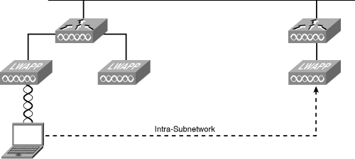
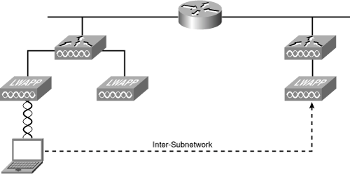
Layer 2 (intra-subnetwork) roaming can be used with a single controller or with multiple controllers in the same subnetwork. Regardless, it is transparent to the client. The client’s session is sustained during connection to the new AP. The client continues using the same DHCP-assigned or static IP address. Figure 18-20 illustrates Layer 2 roaming (intra-subnetwork).
Reauthentication is required if the client sends a DHCP Discover packet with a 0.0.0.0 client IP address or a 169.254.*.* client auto-IP address or when the operator-set session timeout is exceeded.
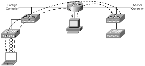
Layer 3 (inter-subnetwork) roaming can be used with multiple Cisco Airespace controllers in different subnetworks. It is still transparent to the client. The session connection to the new AP is sustained as well. Figure 18-21 illustrates Layer 3 roaming (inter-subnetwork).
Tunneling requires special handling of the client traffic between the anchor and foreign controllers. Tunneling the traffic allows the client to continue using the same DHCP-assigned or client-assigned IP address while keeping an active session.
Figure 18-22 illustrates the path traffic takes when on a foreign host subnetwork. First, the client requests information from another host computer and is properly routed to that device. The return path goes back to the anchor controller and is redirected to the foreign controller for final delivery back to the client.
Reauthentication is required if the client sends a DHCP Discover packet with a 0.0.0.0 client IP address or a 169.254.*.* client auto-IP address or when the operator-set session timeout is exceeded.
Features such as the “split MAC” architecture allow the splitting of 802.11 protocols between the AP and the WLAN controller. The Cisco Airespace AP handling the real-time portions of the 802.11 protocols is split from the WLAN controller that handles those items that are not time sensitive.
This patent-pending architecture has revolutionized enterprise wireless networking by splitting the processing of the 802.11 data and management protocols between two devices: the AP and a centralized Cisco Airespace controller. By innovating the way that WLAN controllers handle 802.11 packets, Cisco Airespace has created a robust platform upon which enterprises can deliver business-critical wireless services.
The AP handles the portions of the protocol that have real-time requirements, which include the following:
The frame exchange handshake between a client and AP when transferring a frame over the air
The transmission of beacon frames
The buffering and transmission of frames for clients in power save mode
The response to Probe Request frames from clients
Forwarding notification of received Probe Requests to the controller
Providing real-time signal-quality information to the controller with every received frame
Monitoring each of the radio channels for noise, interference, and other WLANs
Monitoring for the presence of other APs
Encryption and decryption, except in the case of VPN/IPsec clients
All remaining functionality is handled in the Cisco Airespace controller, whereby time-sensitivity is not a concern and controller-wide visibility is required. Some of the MAC layer functions provided in the WLAN controller include the following:
802.11 authentication
802.11 association and reassociation (mobility)
802.11 frame translation and bridging
LWAPP is an open protocol for AP management. In this mode of operation, a WLAN controller system is used to create and enforce policies across multiple different lightweight APs. All functions essential to WLAN operations are centrally controlled by WLAN controllers. In this mode of operation, Cisco APs run a simplified version of Cisco IOS. It is not possible to enter into configuration mode and configure APs individually in this mode.
LWAPP is used for low-overhead communication between the AP and Cisco Airespace controller and is used to encrypt and secure control traffic between the AP and controller.
The UDP control messages are encrypted with an X.509 PKI using Advanced Encryption Standard-Counter Mode with Cipher Block Chaining Message Authentication Code Protocol (AES-CCMP). Data traffic is not encrypted in LWAPP and is switched at the WLAN controller. LWAPP will require 1–4 kbps overhead with associated clients.
Both data traffic and control traffic between the AP and controller are encapsulated. UDP source port 1024 is used for both control and data. Destination port 12222 is used for the data port, and 12223 is used for the control port.
An unknown AP will not be able to “spoof” a Cisco Airespace AP because an X.509 certificate is used. It is used to set up the connection, and encryption keys are dynamically set and rotated.
Note
Time and date are critical in any network using Public Key Infrastructure. Each certificate has validity dates. If the time and date on the Cisco Airespace controller are outside the validity dates on the certificate on the AP, the control channel will not be able to be negotiated.
Note
Although LWAPP is a proprietary protocol, it is being widely adopted because it features very low overhead while allowing such advantages as central control of APs from a WLAN controller.
APs are using LWAPP to connect to the controller, so the following topics deserve a brief discussion:
Layer 2 LWAPP is encapsulated in an Ethernet frame. The controller and AP must be either directly connected or connected to the same VLAN/subnetwork, as illustrated in Figure 18-23.
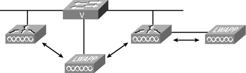
Layer 3 LWAPP is encapsulated in UDP and then an IP packet. The controller and AP can be directly connected, connected to the same VLAN/subnetwork, or connected to a different VLAN/subnetwork, as illustrated in Figure 18-24.
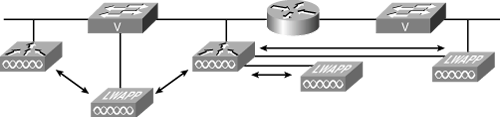
Layer 3 LWAPP requires Cisco Airespace APs to obtain an IP address using DHCP.
The AP attempts to associate using Layer 2 first. Upon failing Layer 2 association, the AP makes a DHCP request and attempts to establish a Layer 3 association. If the Layer 3 association attempt fails, the AP reboots and attempts a Layer 2 association again.
Responses to an AP association request proceed in an orderly fashion. Tthe request is sent, in order until a response is received, to the primary configured controller, the secondary configured controller, and the tertiary configured controller. If no configured controller responds, the response will be from a master controller. Finally, if no master controller responds, the response from the least-loaded controller will then be used.
The Layer 2 communications between the AP and controller use MAC addresses to create the Layer 2 association. The steps applying to all Layer 2 controllers are as follows:
The AP sends an LWAPP Discovery Request to the switch management MAC address via a broadcast.
The switch responds with a Discovery Response from the MAC that includes the current number of APs associated to the controller.
The AP chooses the MAC address with the least number of APs and sends the Join Request.
Enabling Layer 3 communications provides additional features and requires additional steps during the AP and controller association process. Moreover, the Layer 3 communications steps are different depending upon the controller platform used.
The steps applying to the 2006 and 4102 Layer 3 controllers are as follows:
The AP sends an LWAPP Discovery Request to the switch management IP address via a directed broadcast.
The switch responds with a Discovery Response from the AP manager IP address that includes the number of APs currently associated to that AP-manager interface.
The AP chooses the AP-manager IP address with the least number of APs and sends the Join Request.
All subsequent communication is to the switch’s AP-manager IP address.
The steps applying to the 4400 Series Layer 3 controllers are as follows:
The AP sends an LWAPP Discovery Request to the switch management IP address via a directed broadcast.
The switch responds with a Discovery Response from the switch management IP address.
The Discovery Response is modified to contain a list of <AP Manager IP Addresses, Number APs Associated to each Interface> tuples.
The AP chooses the AP-manager IP address with the least number of APs and sends the Join Request.
All subsequent communication is to the switch’s AP-manager IP address.
Although autonomous APs have a significant deployment base, companies may want to start migrating to a more centralized design. WLANs already running in autonomous mode can have a migration path to a centralized lightweight solution. Some APs may already be lightweight capable, such as the Cisco 1200, 1230AG, and 1240AG Series APs.
These APs only need to use the Cisco Autonomous to Lightweight upgrade tool. The APs are upgraded through this tool and have limited capabilities, which include disabled radios until the controller sends the full LWAPP image. The converted AP or lightweight AP is then able to participate in the WLAN via the controller.
During the configuration of the AP, the mode—either local or monitor can be selected. Local mode is the default and is used for most WLANs. Monitor mode is a listen mode for monitoring services.
The lightweight APs offer the same 802.11a/b/g solution as do the autonomous APs. The Cisco 1000 Series Lightweight AP contains a pair of high-gain internal antennas for unidirectional (180-degree) or omnidirectional (360-degree) coverage. The Cisco 1030 Series Lightweight APs are designed for remote edge deployment, and Radio Resource Management (RRM) control via a WAN link includes connectors for external antennas.
Note
The primary difference between the Cisco Airespace APs and Cisco Airespace 1030 APs is that the 1030 APs do not use the data component of LWAPP. The 1030 APs perform local bridging of client traffic, acting much like traditional APs. However, the 1030 APs do have the benefit of being managed by a Cisco Airespace controller via LWAPP, providing the same level of WLAN management available from the Cisco Airespace APs.
The Cisco Remote Edge Access Point (REAP) allows a remote AP to be controlled across a WAN link while keeping client bridged data local. REAPs are implemented in Layer 3 AP mode.
REAPs are designed to support remote offices by extending LWAPP control timers. Control traffic is still LWAPP encapsulated and sent to the controller. Client data is not LWAPP encapsulated but is locally bridged. All management control and RF management is available when the WAN link is up and connectivity is available to the controller. A REAP will continue to provide local connectivity even if the WAN is down.
The controller will support the same number of REAPs as local APs. REAPs can support up to 16 WLANs if controller connectivity is enabled. If controller connectivity is disabled, REAPs goes into standalone mode. REAPs associated to the same controller can provide aggressive load balancing for the wireless clients.
All load balancing for the wireless clients goes unnoticed, as it should. The wireless clients roam around, having liberties that are not afforded to the wired world such as a continuous connection while moving from room to room. Users are able to reach into the enterprise network with advanced security features that meet or exceed security guidelines and policies.
Client devices need only to make an association to the new AP either by actively looking for the specific AP or by surveying it passively with wireless discovery tools.
Wireless clients first send probe requests prior to any associations. The two methods employed to discover APs are passive and active scanning.
The passive scanning steps are as follows:
APs send out beacons announcing the name of the WLAN (SSID), supported rates, and other information.
The client passively scans radio channels for beacons and probe responses, which allows the client to catalog information.
The client chooses an AP sending a beacon with the “right” SSID name and attempts association.
When multiple APs use the same basic service set identifier (BSSID), the client attempts to connect to the AP with the strongest signal and the lowest bit error rate.
The client continues to scan even after connecting to an AP, to efficiently roam from one AP to another or to reduce the reconnection time if it is disconnected from an AP.
Note
The Cisco Airespace controller supports 16 BSSIDs plus one third-party BSSID for a total of 17. With the Cisco Airespace solution, it is possible to turn off broadcast for an SSID on a per-AP basis.
The active scanning steps are as follows:
The client sends out a probe request announcing the name of the WLAN (SSID), supported rates, other information.
The client sends a probe request, actively seeking to join a WLAN. The probe request contains either the SSID of the WLAN the client wants to join or a broadcast indicator.
If the probe request contains an SSID, only the APs that know that SSID will respond.
If the probe request contains a broadcast indicator, then all APs will respond.
Clients can probe for a specific SSID.
The open authentication method allows authorization and associations with or without a WEP key. If the client does not use a WEP key, the client undergoes the normal association process with the AP. The user is then granted access to the network.
If a WEP key is used, both the client and the AP must have matching WEP keys. If the client uses a WEP key that is different from the WEP key of the AP, data traffic cannot be passed because the data is encrypted. Keep in mind that the header is not encrypted; only the payload (or data) is encrypted.
Using open authentication, the client goes through the normal association process, whether or not the client is using a WEP key. Once the client is associated and data transmission begins, a client using a WEP key encrypts the data. If the WEP key on the AP does not match, then the AP is unable to decrypt the data, so it is impossible to send the data via the WLAN.
The initial connection to an AP consists of the following steps:
The client sends a probe request.
Access points A and B each send a probe response. The client evaluates the AP responses and selects the best AP, A in this example.
The client sends an authentication request to access point A.
Access point A confirms authentication and registers the client.
The client sends an association request to access point A.
Access point A confirms association and registers the client.
A wireless client using pre-shared key authentication attempts to associate with an AP. Steps 1 through 3 are the same as those for open authentication:
The client sends an authentication request to access point A.
Access point A sends an authentication response. The authentication response from the access point to the client is sent containing challenge text. This packet is unencrypted.
The client then uses the text from the authentication response to form another authentication packet, which will be encrypted using one of the client WEP keys, and sends this as a response to the access point.
Access point A compares the encrypted challenge text to the access point copy of the encrypted challenge text. If the encrypted text is the same, then the access point allows the client on the WLAN.
Pre-shared key authentication is considered less secure than open authentication because of the challenge text packet. Because this packet is sent unencrypted and then returned as an encrypted packet, it may be possible to capture both packets and determine the stream cipher.
WLAN security is one of the most important things to consider when designing a WLAN. The importance is one of the reasons so many people discuss and research it.
Enhanced 802.11 security incorporates two elements to improve upon standard or “basic” 802.11 security. Authentication and encryption are used with enhanced security both to check user credentials before granting access and to increase the security integrity of the user’s session after association to the network.
Authentication in 802.11 leverages the IEEE 802.1X standard to authenticate users and to permit policy assignment to those users as a result of the authentication transaction. Basing the authentication transaction on user rather than machine credentials reduces the risk of security compromise from lost or stolen equipment. 802.1X authentication also permits flexible credentials to be used for client authentication; password, one-time tokens, PKI certificate, or device ID may be used for authentication. Using 802.1X for wireless client authentication also has the advantage that dynamic encryption keys may be distributed to users each time that they authenticate to the network.
Encryption for 802.11 is enhanced with multiple mechanisms, to aid in protecting the system from malicious exploits against the WEP key and in protecting investment in the system by facilitating encryption improvements in existing hardware.
Temporal Key Integrity Protocol (TKIP) protects the WEP key from exploits that seek to derive the key using packet comparison. Message Integrity Check (MIC) is a mechanism for protecting the wireless system from “inductive attacks,” which seek to induce the system to send either key data or a predictable response that can be analyzed (compared) to known data to derive the WEP key.
Both TKIP and MIC are elements of the Wi-Fi Protected Access (WPA) standard, which is intended to secure a system against all known WEP key vulnerabilities. Note that Cisco implemented a pre-standard version of TKIP and MIC in late 2001 and also supports the Wi-Fi industry-standard TKIP or MIC version.
802.11i encompasses a number of security improvements, including those implemented in WPA. Additionally, 802.11i standardized on a new form of encryption for 802.11, which is wireless Advanced Encryption Standard (AES). AES is recognized as a stronger security algorithm than the RC4 stream cipher used with WEP, although AES is undeniably more processor intensive. Hardware updates will be required to move to AES encryption while maintaining comparable throughput. Table 18-7 summarizes the security evolution overview.
Table 18-7. The Evolution of Wireless LAN Security
Past | First-generation encryption (WEP) No strong authentication, static (breakable keys), not scalable |
Interim | WPA standardized: improved encryption Strong, user-based authentication (e.g., LEAP, PEAP, EAPFAST) |
Present | Wireless IDs: identify and protect against attacks IEEE 802.11i: AES encryption, 802.1X authentication, dynamic key management WPA 2 (WPA2): provides stronger encryption through AES |
Future | Improvements to hashing algorithms and key management in conjunction with AES—192-bit and 256-bit keys |
The Cisco Aironet 802.11a/b/g Wireless LAN Client Adapters (CB21AG and PI21AG) support 802.11a, 802.11b, and 802.11g (2.4 GHz and 5 GHz). Theses cards connect mobile computing devices to the WLAN.
The Cisco Aironet Configuration Administration Tool (ACAT) enables an administrator to install the Aironet Client Utility (ACU) across a network, eliminating the need to install and configure ACU on each wireless client. The auto-installer runs in a silent batch mode and installs and configures ACU (thus configuring the Cisco Aironet client adapter) on a computer running the Windows operating system.
The Cisco Aironet Client Administration Utility (ACAU) enables an administrator to install the Aironet Desktop Utility (ADU) across a network, eliminating the need to install and configure ADU on each wireless client. The auto-installer runs in a silent batch mode and installs and configures ADU (thereby configuring the Cisco Aironet client adapter) on a computer running the Windows operating system.
ACAU and ACAT have virtually identical abilities, just slightly different user interfaces.
On Windows XP, configuration can be done by the Cisco Aironet Wireless LAN Client Adapter through ADU or a third-party tool, such as the Microsoft Wireless Configuration Manager. Because third-party tools may not provide all of the functionality available in ADU, Cisco recommends using ADU. (Please note that a patch from Microsoft might be required to use the Microsoft tool with WPA security.)
Note
If you are selecting a third-party tool, some of the ADU features will not be available. To activate those features, you must install the ADU.
ADU works only with the PC-CardBus card (AIR-CB21AG) and PCI card (AIR-PI21AG). The abilities of ADU are similar to those of ACU; ADU simply has a different look and feel.
ACU is a Windows GUI diagnostic and configuration utility. It allows you to upgrade firmware, edit configuration, and perform RF link testing. ACU allows the wireless client to use different profiles to connect to different WLANs. Each profile allows the user to selectively configure all parameters on the client card. The profile manager can then be used to change profiles. When the user selects a different profile, the settings for the client card are changed without requiring a reboot. ACU can accommodate a maximum of 16 profiles.
The Cisco Compatible Extensions (CCX) program for WLAN devices provides tested compatibility with licensed Cisco infrastructure innovations. Compatibility is assured through extensive, independent testing of third-party devices. The CCX program enables the widespread availability of wireless client devices that take advantage of the Cisco Aironet wireless network, accelerating the availability of innovative features while maintaining interoperability.
With the CCX program, WLAN client suppliers (the program’s participants) license, at no charge, Cisco WLAN technology innovations in a specification. Participants implement all elements of the specification and undergo extensive testing at an independent third-party test lab. The testing helps to ensure support for innovative features pioneered by Cisco Systems, as well as interoperability with Cisco WLAN infrastructure products.
The CCX program helps to ensure that client devices from a variety of suppliers can leverage Cisco-based WLANs. To make it easy to find these devices, Cisco has licensed the Cisco Compatible logo for use by participants whose products pass all tests at the independent third-party test lab. Locating approved wireless devices is as easy as looking for the logo.
The CCX program for WLAN devices provides tested compatibility with licensed Cisco infrastructure innovations.
Lightweight APs are centrally managed via the controller, providing greater scalability than autonomous APs. The centrally managed controller provides various interfaces for connecting and configuring the WLAN. An all-in-one-stop device is available for configuration and verification now.
The WLAN controller provides multiple interface options for configuration. Interfaces are logical entities on the controller. An interface has multiple parameters associated with it, including an IP address, default gateway (for the IP subnet), primary physical port, secondary physical port, VLAN identifier, and DHCP server.
These five types of interfaces are available on the controller:
Management—. Static and configured at setup time; mandatory
AP-manager—. When using Layer 3 LWAPP, static and configured at setup time; mandatory
Virtual—. Static and configured at setup time; mandatory
Service-port—. Static and configured at setup time; optional
Dynamic—. User defined, such as VLANs
Each interface is mapped to at least one primary port, and some interfaces (management and dynamic) can be mapped to an optional secondary (or backup) port. If the primary port for an interface fails, the interface automatically moves to the backup port. In addition, multiple interfaces can be mapped to a single controller port.
The management interface is the default interface for in-band management of the controller and connectivity to enterprise services such as AAA servers. The management interface has the only consistently “pingable” in-band interface IP address on the controller. You can access the controller’s GUI by entering the controller’s management interface IP address in Internet Explorer’s Address field.
The management interface is also used for Layer 2 communications between the controller and Cisco 1000 Series Lightweight APs. It must be assigned to distribution system port 1, but it can also be mapped to a backup port and can be assigned to WLANs if desired. It may be on the same VLAN or IP subnet as the AP-manager interface. However, the management interface can also communicate through the other distribution system ports.
When LWAPP communications are set to Layer 2 (same subnet) mode, the controller requires one management interface to control all inter-controller and controller-to-AP communications, regardless of the number of ports. When LWAPP communications are set to Layer 3 (different subnet) mode, the controller requires one management interface to control all inter-controller communications and one AP-manager interface to control all controller-to-AP communications, regardless of the number of ports.
A controller has one or more AP-manager interfaces, which are used for all Layer 3 communications between the controller and lightweight APs after the APs have joined the controller. The AP-manager IP address is used as the tunnel source for LWAPP packets from the controller to the AP and as the destination for LWAPP packets from the AP to the controller.
The static (or permanent) AP-manager interface must be assigned to distribution system port 1 and must have a unique IP address. It cannot be mapped to a backup port. It is usually configured on the same VLAN or IP subnet as the management interface, but this is not a requirement. The AP-manager interface can communicate through any distribution system port.
The virtual interface is used to support mobility management, Dynamic Host Configuration Protocol (DHCP) relay, and embedded Layer 3 security such as guest web authentication and VPN termination. It also maintains the DNS gateway host name used by Layer 3 security and mobility managers to verify the source of certificates when Layer 3 web authorization is enabled.
Specifically, the virtual interface plays these three primary roles:
It acts as the DHCP server placeholder for wireless clients that obtain their IP address from a DHCP server.
It serves as the redirect address for the Web Authentication Login window.
It acts as part of the IPsec configuration when the controller is used to terminate IPsec tunnels between wireless clients and the controller.
The virtual interface IP address is used only in communications between the controller and wireless clients. It never appears as the source or destination address of a packet that goes out a distribution system port and onto the switched network. For the system to operate correctly, the virtual interface IP address must be set (it cannot be 0.0.0.0), and no other device on the network can have the same address as the virtual interface. Therefore, the virtual interface must be configured with an unassigned and unused gateway IP address, such as 1.1.1.1. The virtual interface IP address is not pingable and should not exist in any routing table in your network. In addition, the virtual interface cannot be mapped to a backup port.
The service-port interface controls communications through and is statically mapped by the system to the service port. It must have an IP address on a different subnet from the management, AP-manager, and any dynamic interfaces, and it cannot be mapped to a backup port. This configuration enables you to manage the controller directly or through a dedicated operating system network, such as 10.1.2.x, which can ensure service access during network downtime.
The service port can obtain an IP address using DHCP, or it can be assigned a static IP address, but a default gateway cannot be assigned to the service-port interface. Static routes can be defined through the controller for remote network access to the service port.
Dynamic interfaces, also known as VLAN interfaces, are created by users and designed to be analogous to VLANs for WLAN clients. A controller can support up to 512 dynamic interfaces (VLANs). Each dynamic interface is individually configured and allows separate communication streams to exist on any or all of a controller’s distribution system ports. Each dynamic interface controls VLAN and other communications between controllers and all other network devices, and each acts as a DHCP relay for wireless clients associated to WLANs mapped to the interface. You can assign dynamic interfaces to distribution system ports, WLANs, the Layer 2 management interface, and the Layer 3 AP-manager interface, and you can map the dynamic interface to a backup port.
You can configure zero, one, or multiple dynamic interfaces on a distribution system port. However, all dynamic interfaces must be on a different VLAN or IP subnet from all other interfaces configured on the port. If the port is untagged, all dynamic interfaces must be on a different IP subnet from any other interface configured on the port.
Connecting to the controller is similar to the standard switch connection. Configure the terminal emulator (HyperTerminal, ProComm, and so on) with the following parameters: 9600 baud, 8 data bits, 1 stop bit, no parity, and no hardware flow control.
Next, use a null-modem serial cable to connect the CLI console to the controller console port.
Note
The controller end of the cable is female DB-9. The other end should be any kind of connector that plugs into your VT-100 terminal emulator (usually a laptop or palmtop computer).
The initial setup for all controllers can be done through the serial port. Moreover, the Service Interface port is another setup option available only on the 4400 Series controllers.
Using the serial port requires a male DB-9 pin connector that supports pins 2, 3, and 5. This is the default port configuration.
The serial port of all WLAN controllers is dedicated to the management of the AireOS operating system. It ensures access to AireOS in the event of a network failure and can be used for initial installation too. The serial port access will only be available from the CLI—not the GUI.
On the 4400 WLAN controller, the Service Interface port is dedicated to AireOS management in addition to the Serial port. The Service Interface port ensures access to AireOS in the event of a network failure and can be used for initial configuration or out-of-band (OOB) management from the management network.
The Service Interface port is an auto-sensing 10/100BASE-TX Ethernet port. The WLAN controller is a DTE type device that requires a crossover cable for other DTE devices such as a router or end station. Standard Category 5 Ethernet cables are used when connecting to a DCE device such as a switch or modem. By default, the port IP address assigned is 192.168.1.1/24.
Note
The controller supports five Telnet/SSH sessions plus one serial port connection simultaneously by default. The serial port can support up to a 115-kbps baud rate.
After the connection is made and power is applied to the WLAN controller, the boot sequence will provide additional options. The boot options available, because this is set in PROM to ensure controller recovery, are as follows:
Run primary image
Run backup image
Manually upgrade primary image
Change active boot image
Clear configuration
Note
The clear configuration option allows you to remove the current configuration and return to factory defaults. This is a two-step process. You must first choose option 5 and then choose an image.
Connection to the controller can be made from a web browser after bootup. Cisco Switch Web Configuration Wizard Login is a GUI tool with an easy-to-use interface. The initial system configuration supports only HTTP access, so if you attempt to use HTTPS, you will receive an error.
The default IP address for Cisco WLAN controllers is 192.168.1.1/24. The default username/password combination is admin/admin.
When selecting the primary or backup image at the Boot Options menu, the system automatically starts if the Esc key is not pressed. After the boot image loads, the Airespace AireOS starts up.
Note
The message “Checking for new bootloader: Not found” will be observed only after initial controller boot or controller upgrade.
Watching the bootup messages enables you to follow the overall process, such as:
APs will not light up until the PoE services are okay as displayed by the message ‘Starting Power Over Ethernet Services: ok’.
Web Authentication Certificate not found (error) is only after the initial controller boot or controller upgrade.
The Cisco Airespace Wizard Configuration Tool begins automatically if there are no saved binary configuration files. The bootup script will run either the CLI or Switch Web Interface Configuration Wizard.
Note
Power-on self test (POST) and controller boot will normally take about 3 minutes. If an Enhanced Security Module (ESM) is installed, it might take an additional 60 seconds for the boot process to complete.
If there is a configuration saved on the controller, the bootup script will prompt for the administrator username and password. Once logged in to the controller AireOS, the show running configuration command provides a general summary of the configuration. It is not in a command syntax format and contains no MAC address information, which allows it to be ported to multiple controllers. Be aware of duplicate IP addresses.
As the switches have both a running-configuration and a saved-configuration, so does the controller. So the running-configuration is any command executed and not saved, whereas saved changes create the saved-configuration in NVRAM. Otherwise, a power cycle will drop all running-configuration changes.
When the controller boots at factory defaults, the bootup script runs the configuration wizard, which prompts the installer for initial configuration settings. Follow these steps to enter settings using the wizard on the CLI:
Connect your computer to the controller using a DB-9 null-modem serial cable.
Open a terminal emulator session and connect to the WLAN controller.
At the prompt, log into the CLI. The default username is admin, and the default password is admin.
If necessary, enter reset system to reboot the unit and start the wizard.
The first wizard prompt is for the system name. Enter up to 32 printable ASCII characters.
Enter an administrator username and password, each up to 24 printable ASCII characters.
Enter the service-port interface IP configuration protocol: none or DHCP. If you do not want to use the service port or if you want to assign a static IP address to the service port, enter none.
If you entered none in Step 7 and need to enter a static IP address for the service port, enter the service-port interface IP address and netmask for the next two prompts. If you do not want to use the service port, enter 0.0.0.0 for the IP address and netmask.
Enter the management interface IP address, netmask, default router IP address, and optional VLAN identifier (a valid VLAN identifier, or 0 for untagged).
Enter the Network Interface (Distribution System) Physical Port number. For the controller, the possible ports are 1 through 4 for a front-panel GigE port.
Enter the IP address of the default DHCP server that will supply IP addresses to clients, the management interface, and the service-port interface if you use one.
Enter the LWAPP Transport Mode: LAYER2 or LAYER3.
Enter the Virtual Gateway IP Address. This address can be any fictitious, unassigned IP address (such as 1.1.1.1) to be used by Layer 3 security and mobility managers.
Enter the Cisco WLAN Solution Mobility Group (RF group) name.
Enter the WLAN 1 SSID, or network name. This is the default SSID that lightweight APs use to associate to a controller.
Allow or disallow static IP addresses for clients. Enter yes to allow clients to supply their own IP addresses. Enter no to require clients to request an IP address from a DHCP server.
If you need to configure a RADIUS server, enter yes, and enter the RADIUS server IP address, the communication port, and the shared secret. If you do not need to configure a RADIUS server or you want to configure the server later, enter no.
Enter a country code for the unit. Enter help to list the supported countries.
Enable or disable support for 802.11b, 802.11a, and 802.11g.
Enable or disable Radio Resource Management (RRM) (Auto RF).
The CLI allows operators to use a VT-100 emulator to locally or remotely configure, monitor, and control a WLAN controller and its associated lightweight APs. The CLI is a simple text-based, tree-structured interface that allows up to five users with Telnet-capable terminal emulators to access the controller. The CLI basic command set is as follows:
linktest—. If the client is a Cisco client, the Cisco Airespace controller will run the Cisco linktest program to test connectivity. If the client is not a Cisco client, 20 pings are sent to the destination MAC address, which will return a Relative Signal Strength Indicator (RSSI) value. You cannot use variables for the MAC address.
logout—. Exit the current CLI session.
ping—. Packet internet groper sends three Internet Control Message Protocol (ICMP) requests to a specified IP address.
reset—. Allows soft reboot of the Cisco Airespace controller.
save configuration—. Data is saved to NVRAM and is preserved in the event of a power cycle.
The GUI allows up to five users to simultaneously browse into the controller http or https (http + SSL) management pages to configure, control, and monitor the operational status for the controller and its associated lightweight APs. The GUI menu bar is as follows:
MONITOR—. Provides a view of this controller, its APs, and wireless clients
WLANs—. Provides WLAN configurations such as SSIDs and security policies for all user groups
SWITCH—. Provides controller-wide configurations, such as Layer 2/3 mode, multicast, and mobility settings
WIRELESS—. Provides AP configurations, client management, and various RF settings
SECURITY—. Provides integration into the security structure, such as RADIUS connectivity
MANAGEMENT—. Provides integration into the network, such as IP addressing and SNMP
COMMANDS—. Provides administrative options, such as upgrades and backups
Logout—. Exits the current switch web interface session
PING—. Sends three ICMP requests to a specified IP address
Save configuration—. Saves data to NVRAM and preserves it in the event of a power cycle
Note
The switch web interface will refresh every 5 minutes, but when looking at statistics, it is recommended to observe the latest information, which can be provided by clicking Refresh. The switch web interface has a default inactivity timeout of 10 minutes.
After Switch Web Configuration Wizard saves the configuration and reboots the controller, HTTPS access will be enabled whereas HTTP access will be disabled by default.
Note
You can connect using either HTTP://controller-IP-Address or HTTPS://controller-IP-address but HTTP is disabled by default. You can disable either HTTP or HTTPS access. If you receive a “The page cannot be displayed” error message, check to see if the corresponding access method has been disabled.
Knowledge and awareness are gained via the show commands. They are a set of robust commands that display what the current WLAN configuration is running.
Use the show 802.11 commands to display configuration parameters.
To display basic 802.11a options and settings, use the following command:
show 802.11aDefaults: None
Related commands: show 802.11b
Use the show advanced commands to display advanced configuration parameters.
To display the 802.11a advanced options and settings, use the following command:
show advanced 802.11a summaryRelated commands: show advanced 802.11b summary
Use the show ap commands to display AP parameters.
To display the detailed configuration for an 802.11b/g Cisco 1000 Series Lightweight AP, use the following command:
show ap config {802.11a | 802.11b | general} Cisco_AP
Defaults: None
Related commands: show ap auto-rf, show ap bmode, show ap bhrate, show ap core-dump, show ap crash-file, show ap stats, show ap summary, show ap wlan, show arp switch, show auth-list, show boot
Use the show stats commands to display controller statistics.
To show physical port receive and transmit statistics, use the following command:
show stats port {detailed port | summary port}
Table 18-11. Syntax Description
show | Display Configurations |
|---|---|
stats | Statistics |
port | Port |
detailed | Display detailed port statistics |
summary | Display port summary statistics |
port | Physical port number: • 1 through 4 on Cisco 2000 Series WLAN controllers • 1 or 2 on Cisco 4100 Series WLAN controllers • 1 or 2 on Cisco 4402 Series WLAN controllers • 1 through 4 on Cisco 4404 Series WLAN controllers • 1 on Cisco WLCM Series WLAN controllers |
Related commands: show stats switch, show switchconfig, show sysinfo, show syslog, show tech-support, show time, show trapflags, show traplog, show watchlist, show wlan, show wps
Use the show client commands to display client settings.
To display the clients on a Cisco 1000 Series Lightweight AP, use the following command:
show client ap {802.11a | 802.11b} Cisco_AP
Note
The show client ap command may list the status of automatically disabled clients. Use the show exclusionlist command to view clients on the exclusion list (blacklisted).
Defaults: None
Related commands: show client ap, show client detail, show client summary, show client username, show country, show cpu, show custom-web, show database summary, show debug, show dhcp, show eventlog, show exclusionlist, show ike, show interface, show inventory, show ipsec, show known ap, show l2tp, show load-balancing, show location summary, show loginsession, show macfilter
To display the RADIUS accounting server statistics for the Cisco WLAN controller, use the following command:
show radius acct statisticsDefaults: None
Related commands: show radius auth statistics, show radius rfc3576 statistics, show radius summary
Use the show rogue ap commands to display rogue AP settings.
To show details of rogue AP clients detected by the Cisco WLAN controller, use the following command:
show rogue ap clients MAC
Defaults: None
Related commands: show rogue ap clients, show rogue ap summary
Use the show rogue client commands to display the rogue client settings.
To show details of a rogue client detected by a Cisco WLAN controller, use the following command:
show rogue client detailed MAC
Defaults: None
Related commands: show rogue client summary
Additional show commands exist covering configuration designs such as mobility, X.509 certificates, RFIDs, and mesh networking. All require further exploration into the world of wireless networking.
The move to 2.4 GHz put WLAN products into a “cleaner” radio frequency (RF) environment, making it possible to deploy data collection systems without the worries of 900-MHz interference. WLAN products are designed using the IEEE 802 family of LAN specifications, which 802.11 falls under. Understanding the similarities between Ethernet and wireless makes it easier to understand 802.11. However, the security, connectivity, regulatory, and power-related issues associated with WLANs make the differences start to stand out.
Wireless components such as the client cards, APs, and controllers are obvious differences from Etherenet that are required to make WLANs work. WLAN components are the building blocks of AP topologies such as infrastructure, bridging, or mesh designs. Those building blocks and RF knowledge create the foundation to any wireless design. The results are always better when considering RF propagation issues such as reflection, refraction, diffraction, and absorption. Losses and gains, also, come into play for RF absorption, antenna types, and distances. All those losses and gains require RF math skills to know the end results.
Adding antenna gains and losses requires an understanding of gain and how each type of antenna is used. Moreover, the RF coverage area provided by the antenna defines a microcell layout. Microcells designed for 802.11a do not have the same effective RF coverage area as 802.11b/g microcells.
Omnidirectional antennas are the most widely used, followed by semidirectional antennas for both indoors and outdoors. Highly directional antennas are mostly used for bridging between distant buildings. Keep in mind that all RF links between buildings or indoors are subject to regulatory agency compliance, which may impact the WLAN design. The outdoor antennas need to keep Fresnel zone interferences to less than 40 percent and ideally to less than 25 percent.
The wireless frequency standards provide effective transmissions and reliability of data. Currently, wireless transmission and reliability are so effective that most customers are focusing on other issues such as bandwidth and backward compatibility. 802.11g is meeting the needs of most customers regardless of the channel reuse issues. A well-designed WLAN considers the three separated channels on the ISM band, which are 1, 6, and 11. Moreover, the design may include 802.11a, UNII band, which provides greater ease on channel reuse because 12 channels exist. Using best practices during the design phase reduces a number of issues and eases the implementation phase.
Getting power to the APs cannot be overlooked, and easing that burden is why power injectors and 802.3af-compliant devices exist. The power issue is one of the common concerns enterprises have regarding wireless. That is one of the reasons why Cisco came out with the Unified Wireless Network solution, which has three goals: maintaining network security, managing the network, and unifying the network.
The requested features most enterprises wanted form the core AireOS feature set. Layer 2 roaming is a core feature and is included in the advanced features set. The advanced features provide Layer 3 roaming and advanced security. Most features are carried out on the controller and not on the lightweight AP. The split MAC architecture allows the lightweight AP to split the 802.11 function between the AP and controller. Authentication, reassociation, and frame translation are all handled in the controller. The controller also maintains association to the APs using the Lightweight Access Point Protocol (LWAPP), the low-overhead management protocol. Some autonomous APs can be converted to use LWAPP, such as in an enterprise migration plan.
Cisco wireless clients can create an association either actively or passively. The clients actively send AP authentication requests after the AP probe request. After both responses come back, the AP association request is sent. Passively, the client does not send probes; it is a listen-only mode until the reassociation occurs. The reassociation or association process may include open or pre-shared (WEP) key information for authentication. It is recommended to use a stronger mechanism for security purposes, such as WPA2. Client cards are available from Cisco, and other vendors now support the Cisco Compatibility Extensions (CCX) program.
WLAN controllers that have multiple interfaces support up to five interfaces:
Management—. Static and configured at setup time; mandatory
AP-manager—. When using Layer 3 LWAPP, static and configured at setup time; mandatory
Virtual—. Static and configured at setup time; mandatory
Service-port—. Static and configured at setup time; optional
Dynamic—. User defined, such as VLANs
The connection to the controller can be accomplished using the CLI or service port for web access. Gathering all the pertinent information prior to the configuration is a best practice and may eliminate potential conflicts. Once the configuration setup is complete, use the show commands to verify the configuration.
Planning, designing, implementing, operating, and troubleshooting an enterprise wireless network requires a greater understanding than this brief chapter can provide. Many materials are offered to enable you to learn about and better understand wireless networks, including books, software, websites, and instructor-led courses.