This chapter covers the following topics:
Data Link Layer Technologies Used to Interconnect Multilayer Switches
Designing Cisco Multilayer Switched Networks Using the Cisco Catalyst Switches and Current Data Link Technologies
Chapter 1, “Introduction to Building Cisco Multilayer Switched-Networks,” discussed the design and the switching components of the multilayer switched network. The first section of this chapter continues the tour of building Cisco multilayer switched networks by discussing the data link technologies used to interconnect modules and submodules of the Enterprise Composite Network Model and Cisco Catalyst switches. The second section elaborates on designing Cisco multilayer switched networks using the Enterprise Composite Network Model, the Cisco Catalyst switches, and the data link technologies.
Ethernet-based data link layer technologies that are available on Cisco Catalyst switches include Ethernet, Fast Ethernet, Long-Reach Ethernet (LRE), Gigabit Ethernet, and 10-Gigabit Ethernet. Moreover, for long distances, technologies that provide transparent delivery of Gigabit Ethernet and 10-Gigabit Ethernet are dense wavelength-division multiplexing (DWDM), Synchronous Optical Network (SONET), and coarse wavelength-division multiplexing (CWDM). These topics are covered in Chapter 17, “Performance and Connectivity Troubleshooting Tools for Multilayer Switches.” The original 10-Mbps Ethernet is legacy and should no longer be considered an option for building enterprise networks. 100-Mbps Ethernet is slowly becoming extinct due to the low cost of 10/100/1000-Gbps Ethernet. This section discusses the various data link layer technologies for interconnecting switches and modules in the designing and building of multilayer switched networks.
Legacy Ethernet switching dynamically allocates dedicated 10-Mbps connections to each user on the network. Given advances in Fast Ethernet and Gigabit Ethernet technology and the lower costs associated with these technologies, 10-Mbps Ethernet is not typically used in Enterprise networks except for connection to legacy devices. However, 10-Mbps Ethernet used to be found on the ISP (WAN) interface of the DSL or cable modem for broadband networks in home offices. At the time of publication, most broadband consumer networks only provide up to 6 Mbps of bandwidth; therefore, 100-Mbps Fast Ethernet on the ISP interface of broadband modems is not necessary.
Increasing the speed of the link increases network performance at a very low cost. Whereas Ethernet supports 10 Mbps, Fast Ethernet supports 100 Mbps, Gigabit Ethernet supports up to 1000 Mbps, and 10-Gigabit Ethernet supports up to 10,000 Mbps. In addition, Fast Ethernet technologies generally, and Gigabit Ethernet technologies always, support full-duplex operation. Full-duplex operation is the ability to transmit and receive at the same time, effectively doubling the available bandwidth. Fast Ethernet and Gigabit Ethernet technologies both support auto-negotiation, which is useful in upgrading to higher-speed Ethernet while maintaining interoperability for legacy Ethernet speeds.
Moreover, the availability of powerful, affordable personal computers and workstations is driving the requirement for speed and availability in the campus network. In addition to existing applications, the new generation of multimedia, imaging, and database products easily overwhelms a network running at the traditional Ethernet speeds of 10 Mbps. For example, a high-definition TV broadcast in either 1920 × 1080I (interlaced) or 1280 × 720P (progressive) resolution requires between 11 Mbps and 18 Mbps of bandwidth. As a result, many enterprises are opting to design networks with Gigabit (Ethernet) to the desktop (GTTD).
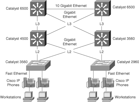
Figure 2-1 illustrates a sample network design that uses different Ethernet technologies together in a single network design.
Regarding cable installations of Ethernet, most cable plant installers recommend following the 100-meter rule when installing unshielded twisted-pair (UTP) cable connections. The 100-meter rule is broken down into the following distance recommendations:
Five meters from the switch to the patch panel
Ninety meters from the patch panel to the office punch-down block (office faceplate)
Five meters from the office punch-down block to the desktop connection
Short cables in a noisy wiring closet result in less induced noise on the wire compared to long cables and result in less crosstalk when used in large multiple-cable bundles. Noise in this context refers to interference caused by fans, power systems, motors, air-conditioning units, and so on. Nevertheless, short cables may restrict switch location in large wiring closets, so the 100-meter rule is occasionally overlooked.
The next section discusses the Fast Ethernet technology that is frequently used in wiring closets to provide device access to the network. However, Gigabit Ethernet technology deployment is rapidly evolving as a choice for device access. A discussion of Gigabit Ethernet follows the discussion of Fast Ethernet.
From a deployment standpoint, Fast Ethernet in today’s networks provides legacy PC and workstation network access at 100 Mbps. At 100 Mbps, data can move from 10 to 100 Mbps without protocol translation or changes to application and networking software. Fast Ethernet also maintains the 10BASE-T error control functions, frame format, and frame length. The most important aspect of Fast Ethernet is backward-compatibility. Fast Ethernet interfaces and the IEEE 802.3ab Gigabit Ethernet over copper interfaces optionally support auto-negotiation to 10 Mbps, and 100 Mbps in the case of Gigabit Ethernet. In this manner, new deployments that maintain backward capability ease installation while allowing for scaling to new, higher-speed Ethernet technologies. The “Fast Ethernet and Gigabit Ethernet Auto-Negotiation” section of this chapter discusses this topic in more detail. In addition, the IEEE 802.3-2002 standard now encompasses all Gigabit Ethernet specifications.
Fast Ethernet devices generally support full-duplex operation, which doubles the effective bandwidth to 200 Mbps. While Fast Ethernet defaults to half-duplex operation in the absence of auto-negotiation, Gigabit Ethernet defaults to full-duplex operation in the absence of auto-negotiation. With Gigabit Ethernet, the 802.3ab specification requires that all Gigabit Ethernet–capable devices support auto-negotiation. Current Cisco Catalyst switches support 10/100-Mbps auto-negotiation on all copper Fast Ethernet interfaces and full duplex on all fiber Fast Ethernet interfaces.
Specifications define Fast Ethernet to run over both UTP and fiber cable plants. Table 2-1 illustrates the wire category and maximum cable length for the Fast Ethernet standards.
Table 2-1. Ethernet Wire Standards and Maximum Distances
Wire Category | Maximum Cable Length in Switch Media | |
|---|---|---|
100BASE-TX | EIA/TIA Category 5 (UTP) Unshielded twisted-pair 2 pair | 100 meters |
100BASE-T4 (not supported on a Cisco device) | EIA/TIA Category 3, 4, 5 (UTP) Unshielded twisted-pair 4 pair | 100 meters |
100BASE-FX | MMF cable, with a 62.5-micron fiber-optic core and 125-micron outer cladding (62.5/125) | 400 meters (half duplex) 2000 meters (full duplex) |
Gigabit Ethernet is the most effective choice for interconnecting and designing the Building Access submodule, Building Distribution submodule, Campus Backbone submodule, and the Data Center.
The current design recommendations call for Gigabit Ethernet to connect the access layer switches in the Building Access submodule to the distribution layer switches in the Building Distribution submodule with at least multiple Gigabit Ethernet links if not 10-Gbps Ethernet. Another guideline in designing the campus infrastructure is to use multiple Gigabit Ethernet interfaces for redundancy and load balancing where possible. Figure 2-1 in the previous section illustrates a sample topology using multiple Gigabit links to connect switches in the Building Access submodule to the distribution switches in the Building Distribution submodule.
In the Building Distribution and Campus Backbone submodules, the current design recommendations call for all Building Distribution and Campus Backbone submodules to interconnect with at least multiple Gigabit Ethernet links if not 10-Gbps Ethernet. For high-bandwidth networks, deploying multiple Gigabit Ethernet links between switches for load balancing and redundancy in the Campus Backbone and Building Distribution submodules is necessary. Two methods of combining multiple Gigabit Ethernet interfaces for load balancing are Cisco EtherChannel and 803.ad port channeling. Chapter 7, “Enhancing Network Stability, Functionality, Reliability, and Performance Using Advanced Features,” discusses these port-channeling technologies in more detail. 10-Gigabit Ethernet has emerged as the leading choice for interconnecting switches in high-bandwidth enterprise campus networks and Data Centers.
Gigabit Ethernet is also well suited for connecting high-performance servers and even desktop workstations to the network. A high-performance UNIX, Windows application, or video server is easily capable of flooding three or four Fast Ethernet connections simultaneously. In addition, current-generation network interface cards (NIC) for servers are capable of TCP checksum calculations, IP checksum calculations, TCP/IP packet builds, and iSCSI (SCSI over IP) protocols in hardware, enabling 200-MBps throughput with very low CPU utilization. As servers and server NICs grow in power and throughput, along with the trend for centralizing servers within the campus network, Gigabit Ethernet has become a necessity within the Data Center.
Although 10-Gbps Ethernet is becoming available for servers, it is not yet widely deployed. Even high-end servers cannot fully achieve 10 Gbps of line rate network speed. In addition, x86 and SPARC architectures are really not capable of achieving such high sustained data rates of 10 Gbps. As such, future technologies will yield lower-latency protocols such as InfiniBand and newer server technologies such as virtualization and Remote Direct Memory Access (RDMA) that will allow data rates of 10 Gbps and beyond.
To achieve load balancing, a Gigabit Ethernet–capable switch is typically centrally located in the Data Center module. The design recommends that the servers in this module connect to switches via multiple autonomous NICs for load balancing and redundancy. Table 2-2 summarizes the Gigabit Ethernet deployment strategy for building Cisco multilayer switched networks. An alternate popular design is “top of rack,” where a Catalyst 6503, 6504, or 4948G is used to aggregate server connections on a per-rack basis.
Table 2-2. Gigabit Ethernet Deployment Strategy in the Enterprise Composite Network Model
Module | Deployment Strategy |
|---|---|
Building Access submodule | Gigabit Ethernet is becoming the de facto standard for workstations and end-user devices in today’s networks; that said, almost all mid- to high-end workstations and laptops are beginning to ship with Gigabit Ethernet interfaces installed. |
Building Distribution submodule | Gigabit Ethernet provides multiple high-speed connections between the Building Access and Building Distribution devices. It is recommended to use port-channel to aggregate multiple Gigabit Ethernet links in this submodule. |
Campus Backbone submodule | Gigabit Ethernet and 10-Gigabit Ethernet provide high-speed connectivity to the Building Distribution submodule and to the Data Center module with multiple Gigabit Ethernet links. Gigabit Ethernet also provides high-speed interconnectivity between Campus Backbone submodule devices with multiple Gigabit Ethernet links. As with the Building Distribution submodule, use port-channel to aggregate multiple Gigabit Ethernet links. |
Data Center Module | Gigabit Ethernet provides Gigabit Ethernet speeds to servers and network appliances. Most servers require Gigabit Ethernet because they are able to achieve throughput in hundreds of megabytes per second. New technologies such as ROMA are forthcoming. |
Architecturally, Gigabit Ethernet upgrades the Ethernet physical layer, increasing data-transfer speeds tenfold over Fast Ethernet, to 1000 Mbps (1 Gbps). Gigabit Ethernet runs over copper or fiber.
Because Gigabit Ethernet makes significant use of the Ethernet specification and is optionally backward-compatible with Fast Ethernet on copper interfaces, customers are able to leverage existing knowledge and technology to install, manage, and maintain Gigabit Ethernet networks.
To increase speeds from 100-Mbps Fast Ethernet up to 1 Gbps, several changes were made to the physical interface. Gigabit Ethernet looks identical to Ethernet from the data link layer and upward of the OSI reference model. The IEEE 802.3 Ethernet and the American National Standards Institute (ANSI) X3T11 Fibre Channel were merged to create a specification for providing 1-Gbps throughput over fiber.
Table 2-3 defines the Gigabit Ethernet specifications and distance limitations per media type.
Table 2-3. Distance Limitations for Gigabit Ethernet
Standard | Wire Category | Maximum Cable Length in Switch Media |
|---|---|---|
1000BASE-CX (not supported on any Cisco device) | Copper shielded twisted-pair | 25 meters |
1000BASE-T | Copper EIA/TIA, Category 5, unshielded twisted-pair (4 pair) | 100 meters |
1000BASE-SX | Multimode fiber cable using a 62.5- or 50-micron fiber-optic core with a 780-nanometer laser | 260 meters with 62.5-micron fiber-optic core (multimode fiber) 550 meters with 50-micron fiber-optic core (multimode fiber) |
1000BASE-LX | Single-mode fiber cable with 9 micron core and 1300-nanometer laser | 3 km (Cisco supports up to 10 km) |
1000BASE-ZX | Single-mode fiber cable with 9 micron core and 1550-nanometer laser | 70 to 100 km depending on whether premium single-mode fiber or dispersion-shifted single-mode fiber |
Note
1000BASE-LX and 1000BASE-ZX require minimum distances, and short distances may require attenuators to prevent burnout of the internal receivers. In the case of 1000BASE-ZX, 5-dB or 10-dB attenuators are necessary for fiber-optic cable spans of less than 15.5 miles (25 km).
In addition, Gigabit Ethernet defaults to full-duplex operation, for effective bandwidth of 2 Gbps, and all Gigabit technologies require auto-negotiation that includes methods for link integrity and duplex negotiation. As a result, Gigabit Ethernet auto-negotiation is superior in compatibility and resiliency to Fast Ethernet.
Fast Ethernet and Gigabit Ethernet auto-negotiation is useful in scaling networks to newer Ethernet technologies while maintaining backward compatibility. Until recently, auto-negotiation was not resilient in its interoperability. At press time, the technologies covered in this section are almost considered legacy, because Gigabit Ethernet auto-negotiation has brought more stability to the feature. Furthermore, because of recent improvements in the capability of auto-negotiation and vendor testing, however, auto-negotiation is becoming a useful tool in upgrading networks, especially networks migrating to 10/100/1000 Gigabit Ethernet in the Building Access submodule.
One caveat with auto-negotiation is that manual configurations of 100 Mbps at full duplex do not interact properly with interfaces configured for auto-negotiation. This is a result of the IEEE 802.3u specification requiring interfaces to send auto-negotiation parameters for link partners only when those partners are configured for auto-negotiation. If one link partner is hard-coded to 100 Mbps, full duplex and the other link partner is configured for auto-negotiation, a duplex mismatch results because the auto-negotiating link partner did not receive auto-negotiation parameters from the other link partner; when such a situation occurs, the auto-negotiating link defaults to half duplex, as defined in the IEEE 802.3u specification. Duplex mismatches result in very poor performance and Layer 2 error frames.
Table 2-4 summarizes the valid auto-negotiation settings. Appendix A discusses these issues and auto-negotiation in more detail.
Table 2-4. Valid Fast Ethernet Auto-Negotiation Configuration Table
Configuration of NIC (Speed, Duplex) | Configuration of Switch (Speed, Duplex) | Resulting NIC (Speed, Duplex) | Resulting Switch (Speed, Duplex) | Comments |
|---|---|---|---|---|
AUTO | AUTO | 100 Mbps, full duplex | 100 Mbps, full duplex | Assuming maximum capability of Catalyst switch and NIC is 100 full duplex |
100 Mbps, full duplex | AUTO | 100 Mbps, full duplex | 100 Mbps, half duplex | Duplex mismatch |
AUTO | 100 Mbps, full duplex | 100 Mbps, half duplex | 100 Mbps, full duplex | Duplex mismatch |
100 Mbps, full duplex | 100 Mbps, full duplex | 100 Mbps, full duplex | 100 Mbps, full duplex | Correct manual configuration |
100 Mbps, half duplex | AUTO | 100 Mbps, half duplex | 100 Mbps, half duplex | Link is established, but switch does not see auto-negotiation information from NIC and defaults to half duplex |
10 Mbps, half duplex | AUTO | 10 Mbps, half duplex | 10 Mbps, half duplex | Link is established, but switch will not see FLP and will default to 10 Mbps, half duplex |
10 Mbps, half duplex | 100 Mbps, half duplex | No link | No link | Neither side will establish link due to speed mismatch |
AUTO | 10 Mbps, half duplex | 10 Mbps, half duplex | 10 Mbps, half duplex | Link is established, but NIC will not see FLP and will default to 10 Mbps, half duplex |
Note
Always manually configure speed and duplex settings for 10/100-Mbps Fast Ethernet and 10/100/1000-Mbps Gigabit Ethernet on both link partners for critical connections to servers or third-party equipment. Use auto-negotiation for interconnecting Cisco devices and user workstations.
Interfaces capable of 10/100/1000BASE-T operation use auto-negotiation to first recognize 100-Mbps capability and then exchange encoded information to determine 1000BASE-T operation.
10-Gigabit Ethernet uses the IEEE 802.3 Ethernet MMAC protocol, the IEEE 802.3 Ethernet frame format, and the IEEE 802.3 frame size. 10-Gigabit Ethernet is full duplex, and it minimizes the user’s learning curve from Gigabit Ethernet by maintaining the same management tools and architecture.
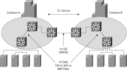
The 10-Gigabit Ethernet is becoming the de facto standard for new deployments by both service providers and enterprise networks. One primary use of 10-Gigabit Ethernet in the LAN is to aggregate multiple Gigabit Ethernet segments, such as those between buildings, to build a single, high-speed backbone. Technologies such as video and mass data storage require extremely high bandwidth. These applications are steadily growing into multiple Gigabit Ethernet speeds and eclipsing into the 10-Gigabit Ethernet range. Figure 2-2 illustrates a network using 10-Gigabit Ethernet in the Campus Backbone submodule.
Currently, 10-Gigabit Ethernet is useful in implementing the following topologies:
Server interconnections for clusters of servers operating at Gigabit Ethernet speeds
Aggregation of multiple 1000BASE-X or 1000BASE-T segments into 10-Gigabit Ethernet uplinks and downlinks
Switch-to-switch links for very high-speed connections between switches in the same data center, in an enterprise backbone, or in different buildings
Interconnecting multiple multilayer switched networks
High-speed server connections
10-Gigabit Ethernet physical layer interfaces, written as 10GBASE-xyz, tend to use the following general naming convention:
Prefix (10GBASE-)—. 10-Gbps baseband communications
First suffix (x)—. Media type or wavelength, if media type is fiber
Second suffix (y)—. PHY encoding type
Optional third suffix (z)—. Number of wide wavelength-division multiplexing (WWDM) wavelengths or XAUI lanes
In the example in Table 2-5, a 10GBASE-LX4 optical module uses a 1310-nanometer (nm) laser, LAN PHY (8B/10B) encoding, and four WWDM wavelengths. A 10GBASE-SR optical module uses a serial 850-nm laser, LAN PHY (64B/66B) encoding, and one wavelength. The IEEE 802.3an task force is targeting to finalize the standard for 10-Gigabit Ethernet over twisted-pair copper cabling (10GBASE-T) by early 2007.
Table 2-5. 10GBASE Written Nomenclature
Prefix | First Suffix = Media Type or Wavelength | Second Suffix = PHY Encoding Type | Third Suffix = Number of WWDM Wavelengths or XAUI Lanes |
|---|---|---|---|
10GBASE- | Examples: C = Copper (twin axial) S = Short (850 nm) L = Long (1310 nm) E = Extended (1550 nm) Z = Ultra extended (1550 nm) | Examples: R = LAN PHY (64B/66B) X = LAN PHY (8B/10B) W = WAN PHY (64B/66B) | Examples: If omitted, value = 1 (serial) 4 = 4 WWDM wavelengths or XAUI lanes |
Table 2-6 summarizes the operating ranges and media types supported for various 10-Gigabit Ethernet interfaces that would be used in enterprise deployments.
Table 2-6. 10-Gigabit Ethernet Typical Deployments and Distances
10GE Physical Interface | Typical Deployment | Operating Range Over: | |||
|---|---|---|---|---|---|
62.5-micron Multimode Fiber (FDDI Grade) | 50-micron Multimode Fiber (MMF) | 10-micron Single-Mode Fiber (SMF) | Twin-axial Copper | ||
10GBASE-CX4 | Data Center | N/A | N/A | N/A | 15m |
10GBASE-SR | Data Center | 26–33m | 66–300m | N/A | N/A |
10GBASE-LX4 | Campus or Data Center | 300m | 240–300m | N/A | N/A |
10GBASE-LR | Campus or Metro | N/A | N/A | 10 km | N/A |
10GBASE-ER | Metro | N/A | N/A | 40 km | N/A |
10GBASE-ZR | Metro or Long-Haul | N/A | N/A | 80 km | N/A |
DWDM | Metro or Long-Haul | N/A | N/A | 80 km-32 wavelengths over single-strand SMF | N/A |
Note
More than 75 percent of existing fiber cabling plants from the campus distribution layer to the wiring closet is FDDI-grade (62.5 micron) MMF, and the distance requirements are typically greater than 100 meters (m). Thus, deploying 10-Gigabit Ethernet to wiring closets over existing FDDI-grade MMF will typically require the 10GBASE-LX4 optical module.
A Gigabit Interface Converter (GBIC) is an industry-standard modular optical interface transceiver for Gigabit Ethernet ports. The GBIC’s primary role is to link the physical port with the fiber-optic cable. The use of modular GBICs allows for scalability by providing a method for each Gigabit Ethernet interface to use different media types. These media types include 1000BASE-T, 1000BASE-SX, 1000BASE-LX, and 1000BASE-ZX. GBICs are hot-swappable and are available in standard form for fiber with SC connectors and in Small Form-Factor Pluggable (SFP) form for fiber with LC connectors.
For buildings, infrastructures, neighborhoods, and campuses with existing Category 1, 2, or 3 wiring, LRE technology extends Ethernet at speeds from 5 to 15 Mbps (full duplex) and distances up to 5000 feet. The Cisco LRE technology delivers broadband service on the same lines as plain old telephone service (POTS), digital telephone, and ISDN traffic. In addition, Cisco LRE supports modes that are compatible with asymmetric digital subscriber line (ADSL), allowing service providers to provide LRE for buildings where broadband services already exist.
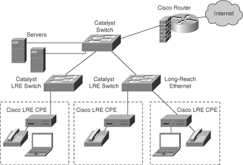
The Cisco LRE solution includes Cisco Catalyst LRE switches, the Cisco LRE customer premises equipment (CPE) device, and the Cisco LRE POTS splitter. Figure 2-3 illustrates a sample LRE topology. The topology in this example illustrates a service provider that is providing access to users throughout a neighborhood.
You can extend Ethernet links between enterprise campuses through a service provider network using metro Ethernet solutions. As shown in Figure 2-4, two enterprise campuses use a metro Ethernet network, connected through multilayer switches, to connect to each other and to a backup data center.
Metro Ethernet is popular in enterprise networks where remote sites need high bandwidth that technologies such as Frame Relay, ISDN, POTS, and broadband are not able to provide. The main difference between metro Ethernet and LRE is speed. Metro Ethernet is meant to connect many high-bandwidth sites, whereas LRE is meant to connect many remote users or low-bandwidth remote sites. LRE has distance limitations of 5000 feet but is capable of using legacy wiring for connections. Metro Ethernet includes DWDM and Ethernet over SONET solutions.
Chapter 1 presented the Enterprise Composite Network Model of the enterprise network and the individual Cisco Catalyst switches that build the Enterprise Composite Network Model. The previous section illustrated the methods by which to interconnect the Cisco Catalyst switches in the Enterprise Composite Network Model. This section uses all these building blocks to illustrate sample network topologies using the Enterprise Composite Network Model, the Cisco Catalyst switches, and the data link technologies.
The Campus Infrastructure module includes the Building Access, Building Distribution, and Campus Backbone submodules, as discussed in Chapter 1. Layer 2 access switches in the Building Access submodule connect end-user workstations, IP phones, and devices to the Building Distribution submodule. Switches here, typically placed in a wiring closet, perform important services such as broadcast suppression, protocol filtering, network access, multicast services, access control, and QoS.
In the Building Distribution submodule, switches are almost always multilayer but could be Layer 2 switches depending on implementation needs. The switches provide aggregation of wiring closets, usually performing routing, QoS, and access control.
In the Campus Backbone submodule, Layer 3 switches provide redundant and fast-converging connectivity between Building Distribution submodules, and between the Data Center and Edge Distribution modules. Layer 3 switches in this module typically route and switch traffic as quickly as possible from one network module to another. In special circumstances, Layer 2 switches are used for port density. In this layer, the switches almost always perform routing, QoS, and security features.
The development of Layer 2 switching in hardware several years ago led to network designs that emphasized Layer 2 switching. These designs are often characterized as “flat” because they are most often based on the campus-wide VLAN model in which a set of VLANs spans the entire network. This type of architecture favored the departmental segmentation approach where, for example, all marketing or engineering users needed to exist on their own broadcast domain to avoid crossing slow routers. Because these departments could exist anywhere within the network, VLANs had to span the entire network. Chapter 4, “Implementing and Configuring VLANs,” discusses VLANs in more detail.
Layer 3 switches provide the same advantages as Layer 2 switches and add routing capability. Layer 3 switches perform IP routing in hardware for added performance and scalability. Adding Layer 3 switching in the Building Distribution and Campus Backbone submodules of the Campus Infrastructure module segments the campus into smaller, more manageable pieces. This approach also eliminates the need for campus-wide VLANs, allowing for the design and implementation of a far more scalable architecture. In brief, using Layer 3 switches in the Campus Backbone and Building Distribution submodules provides the following characteristics to the network design:
Added scalability
Increased performance
Fast convergence
High network availability
Minimized broadcast domains
Segmentation of IP subnets and network devices
Access control at Layer 3, including IP access lists
QoS classification, marking, policing, and scheduling using IP header information of frames
Easier management
Increased security
Easier troubleshooting
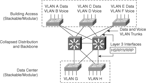
A small campus network design is appropriate for a building-sized network with up to several hundred networked devices. Small campus networks optionally collapse the Campus Backbone and Building Distribution submodules into one layer. The Campus Backbone submodule provides aggregation for Building Access switches. Cost effectiveness in this model comes with a trade-off between scalability and investment protection. The lack of distinct Campus Backbone and Building Distribution submodules and limited port density in the Campus Backbone submodule restrict the scalability of this design.
The building design shown in Figure 2-5 comprises a single redundant building block. The two Layer 3 switches form a collapsed Campus Backbone submodule. The design uses Layer 2 switches in the wiring closets for desktop connectivity. Each Layer 2 switch has redundant Gigabit Ethernet uplinks to the backbone switches. The building design supports servers connected directly to Layer 2 switches or directly to the Layer 3 backbone switches, depending on performance and density requirements.
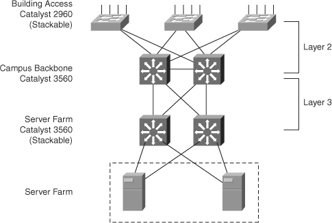
Figure 2-6 illustrates an example of a small enterprise switched network. In this example, the Catalyst 3550 family of switches frames the collapsed Distribution and Campus Backbone submodule. The Catalyst 2960 family of switches in Figure 2-6 comprises the Building Access submodule.
With this design, the network does not contain a single point of failure in the collapsed Distribution and Campus submodule because it provides switch and link redundancy. However, the Catalyst 3560 family of switches does not provide component redundancy and is composed of 32-Gbps switching fabrics, depending on model. (Consult the Cisco product documentation for more details.) For higher-bandwidth networks, consider using the Catalyst 4500 or 6500 family of switches.
In the access layer, the Catalyst 2960 family of switches provides Layer 2 redundancy via Spanning-Tree Protocol. The only downside to using the Catalyst 2960 family of switches is that these switches support only up to a 32-Gbps switching fabric, depending on the model, and up to 48 Gigabit ports. The Catalyst 2960 family of switches currently does not support inline power for Cisco IP phones. Nevertheless, both the Catalyst 2960 and 3560 families of switches support a wide range of QoS features adequate for VoIP deployments.
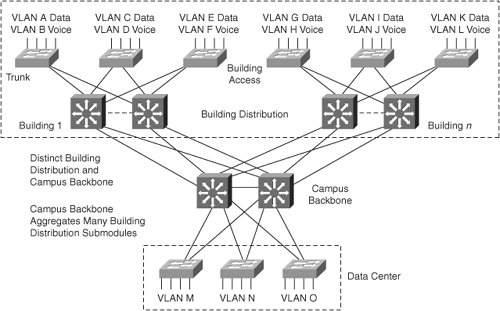
Figure 2-7 shows a medium-sized campus network design with higher availability and higher capacity than the small campus network design. This design includes Layer 3 switches for a more flexible and scalable Campus Backbone submodule. The switches in the Campus Backbone submodule interconnect via routed, Layer 3, Gigabit Ethernet links or routed, Layer 3, Gigabit EtherChannel links.
Using the routed Gigabit Ethernet connections between the backbone switches offers the following advantages:
Reduced router peering for additional stability and scalability
Flexible and fast-converging topology with redundancy based on HSRP or VRRP instead of Spanning-Tree
Multicast and broadcast control in the backbone
Scalability to arbitrarily large network sizes
Figure 2-8 shows an example of a medium-sized multilayer switched network. In this example, the Campus Backbone submodule is composed of a Catalyst 6500 or Catalyst 4500, depending on performance, availability, and scalability requirements. The Catalyst 4500 is able to switch at 64 Gbps with a Supervisor Engine III or IV. With a Supervisor Engine V, the Catalyst 4500 switches up to 96 Gbps. Networks requiring more bandwidth need to use the Catalyst 6500 in the Campus Backbone or Building Distribution submodules as necessary. In this topology, the links between the Campus Backbone and Building Distribution submodules are Layer 3 routed interfaces. In the Building Distribution submodule of Figure 2-8, the Catalyst 4500 acts as a Building Distribution switch while the Catalyst 4500 or 3550 PWR switches provide user and IP phone ports. In this topology, each switch connects to two VLANs: one for voice and one for data. In this manner, HSRP or VRRP is the primary method of redundancy instead of the traditional Spanning-Tree. Later chapters of this book compare and contrast the redundancy methods of Spanning Tree, HSRP, and VRRP.
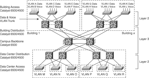
Figure 2-9 shows a multilayer campus design for a large network. One advantage of this multilayer campus design is scalability. An enterprise can easily add new buildings and Data Centers without changing the design. The redundancy of the building block is extended with redundancy in the backbone. If a separate backbone layer is configured, it should always consist of at least two separate switches. Ideally, these switches should be located in different buildings to maximize the redundancy benefits.
The multilayer campus design takes maximum advantage of many Layer 3 services, including segmentation, load balancing, and failure recovery. Broadcasts kept off the Campus Backbone submodule include Dynamic Host Configuration Protocol (DHCP) broadcasts. Cisco Layer 3 routers and switches are able to convert broadcasts such as DHCP to unicasts before packets leave the building block, to minimize broadcast flooding in the Campus Backbone submodule.
In the multilayer model, each Building Distribution submodule switch has two equal-cost paths into the backbone. This model provides fast failure recovery because each distribution switch maintains two equal-cost paths in the routing table to every destination network. All routes immediately switch to the remaining path after detection of a link failure; this switchover typically occurs in one second or less.
Using the Catalyst 6500 family of switches in all submodules is recommended for large campus network designs. By using the Catalyst 6500 family of switches in all submodules, the network design provides for greater availability, scalability, and performance over any other Catalyst family of switches.
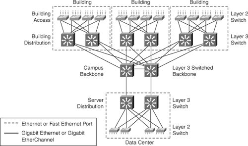
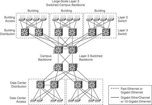
Figure 2-10 shows a Layer 3 switched Campus Backbone submodule on a large scale. This Layer 3 switched backbone easily integrates and supports additional arbitrary topologies because a sophisticated routing protocol, such as Enhanced Interior Gateway Routing Protocol (EIGRP) or Open Shortest Path First (OSPF), is used extensively. Furthermore, the backbone consists of four Layer 3 switches with Gigabit Ethernet or Gigabit EtherChannel links. All links in the backbone are routed links; as a result, the Campus Backbone submodule switches do not use spanning-tree as a redundancy method. Figure 2-10 illustrates the actual scale by showing several gigabit links connected to the backbone switches. A full mesh of connectivity between backbone switches is possible depending on application, traffic patterns, and utilization but is not required by the design. In addition, the Data Center module in this design uses Layer 3 switches.
Figure 2-11 shows an example of a large enterprise switched network. In this example, the design is composed of the Catalyst 6500 family of switches in every submodule. The design optionally allows for the Catalyst 4500 family of switches in the Building Distribution and Building Access submodules for campus infrastructures that do not require the performance, scalability, and availability of the Catalyst 6500 platform.
Within the Data Center, switches provide connectivity between the Data Center and the Campus Backbone submodule in some designs, and possibly providing access between servers and storage-area networks (SAN). This section discusses the role of switches in the Data Center.
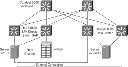
The Data Center contains internal e-mail and corporate servers that provide services such as applications, files, and print services, e-mail, and DNS to internal users. In financial data centers, servers in the Data Center mostly provide application services such as databases and data processing. Nevertheless, because access to these servers is vital to the servers connect to two different switches, enabling full redundancy and load sharing. The Data Center switches cross-connect with Campus Backbone submodule switches, enabling high reliability and availability of all interconnected switches. Figure 2-12 illustrates an example of a Cisco Data Center.
Depending on the type of the enterprise storage model, enterprise networks may use SANs to interconnect storage devices. Because of the recent growth of the iSCSI and FCIP protocols, SANs extension over IP is becoming a popular choice in enterprise networks for disaster-recovery designs. SANs use FCIP networks as FCIP to interconnect autonomous SANs over IP.
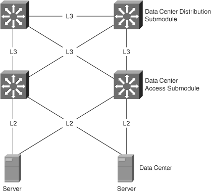
The Data Center module logically divides the overall Data Center infrastructure into the following layers:
Data Center access layer—. Provides Layer 2 connectivity to directly connected servers. Layer 2 switching in the layer provides flexibility and speed. Layer 2 switches also allow deployment of legacy applications and systems that may inherently expect Layer 2–level connectivity.
Data Center distribution layer—. Consists of devices in multiple layers. This layer provides a transit between the Layer 2 and Layer 3 networks. The Data Center distribution layer leverages Layer 3 scalability characteristics while benefiting from the flexibility of Layer 2 services on egress ports to the access layer.
Campus Backbone layer—. Shared by the Campus Infrastructure, Enterprise Edge, and Data Center distribution devices. The Campus Backbone layer consists of high-end switches providing Layer 3 transport between the distribution and edge layers. The design allows for combining the distribution and core layers physically and logically into a collapsed backbone to provide connectivity with the edge layer and the Building Access submodule.
Figure 2-14 illustrates the Data Center infrastructure architecture.
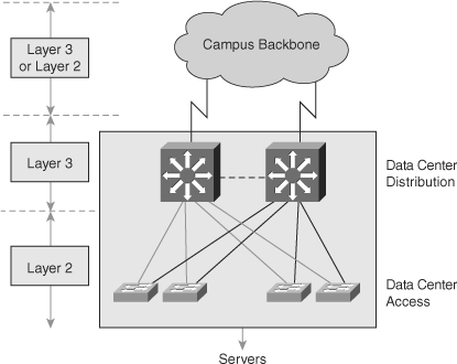
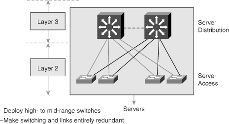
Figure 2-15 illustrates the Data Center distribution layer. The Data Center module architecture calls for the following best practices for designing the Data Center distribution layer:
Deploy high- to mid-range multilayer switches, such as the Catalyst 6500 series, whenever possible.
Implement redundant switching and links with no single points or paths of failure.
Deploy caching systems where appropriate using Cisco Content Networking solutions.
Implement server load balancing using Cisco Content Networking solutions or Cisco IOS.
Implement server content routing using Cisco Content Networking solutions.
In a large network, deploy multiple network devices; in a small network, deploy a single device with redundant logical elements.
Layer 2 in the distribution layer is an option when using service modules for features such as VPN, firewalls, IP Contact Center (IPCC), and IDS.
“Top-of-rack” design is becoming an option to consolidate server Gigabit Ethernet interfaces into several 10-Gbps Ethernet interfaces.
Figure 2-16 illustrates the Data Center access layer. The network model calls for the following best practices for designing the Data Center access layer:
At minimum, deploy mid-range switches such as the Catalyst 6500, 4948G, or 4500 series. A popular choice is the Cisco Catalyst 4948G-10GE switch.
Dual-home all servers with two separate NICs.
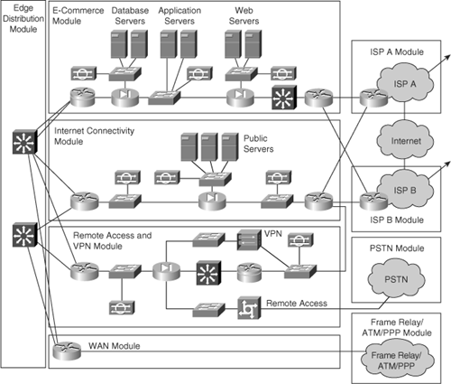
In the Enterprise Edge functional area, switches provide functionality in the E-Commerce and Remote Access and VPN modules. This section discusses the roles of switches in the Enterprise Edge functional area, as illustrated in Figure 2-17.
As illustrated in Figure 2-17, switches perform the distribution function in the Edge Distribution module between the Enterprise Edge module and the Campus Backbone submodule.
In addition, switches play an important role in the various Enterprise Edge submodules. For example, in the E-Commerce module, all e-commerce transactions may pass through a series of intelligent services provided by the Catalyst switches. Intelligent services may include traffic filtering via firewall capabilities and load balancing. The switches themselves provide for the overall e-commerce network design by offering performance, scalability, and availability. Switches also play a role in the server and storage aspects of an e-commerce solution by providing interswitch connectivity and connections to SAN environments.
Another example of Catalyst switch involvement in the Enterprise Edge module, aside from switching traffic and providing individual switches, is remote access and VPN. With specialized hardware and specific software versions, the Catalyst switches can terminate VPN traffic from remote users and remote sites that are reachable through the Internet.
Designing a Cisco multilayer switched network is a fairly detailed task. Designing a switched network requires forethought and research into traffic patterns, utilization, workstation use, end-user applications, and so on. To add a new building to a Campus Infrastructure of a switched network, you need information about the performance, scalability, and availability requirements of all the end devices to be connected to the network.
Consider, for example, having the following performance, scalability, and availability requirements for adding a new building to an enterprise campus:
2000 end users segmented in a single building with approximately 100 users per floor.
Each user has a minimum available bandwidth requirement of 500 kbps to the Campus Backbone submodule.
Application software typically bursts up to 20 MBps (160 Mbps).
Support for a new IP/TV multicast application for end users.
Support for nightly backups.
High availability for IP telephony and data accessibility.
Inline power for IP phones.
The Campus Backbone submodule is already in place, and four Gigabit Ethernet interfaces are available for use. The Data Center is located on a separate module adjoining the Campus Backbone submodule. Therefore, all you need to do is add a Building Distribution submodule and a Building Access submodule for the purpose of adding additional users.
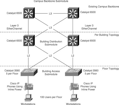
In the Building Access submodule, each floor has 100 users. Five Catalyst 3560-24 PWR switches per floor suffice as the Building Access switches because this switch provides the needed switching fabric capacity, port density for minimum growth per floor, inline power, QoS, and redundant Gigabit Ethernet connections to the Campus Backbone submodule. Although the Catalyst 3560 family of switches is capable of Layer 3 switching, this design uses the Catalyst 3560 switches strictly as Layer 2 switches with Layer 4 QoS features for IP telephony. An alternate solution is to use the Catalyst 3750 family of switches in a stacking configuration per floor.
The use of five switches per floor results in a total of 100-Gigabit Ethernet connections to each Building Distribution switch. To accommodate this large number of Gigabit Ethernet connections per floor, a Catalyst 6500 with a Sup720 is preferable over the Catalyst 4500. Although the Catalyst 4500 is able to accommodate 100-Gigabit Ethernet connections, it cannot achieve line rate on all 100-Gigabit Ethernet interfaces simultaneously because of its limitation of 64 Gbps and line module restrictions. An alternative would be the Catalyst 49486-10GE.
To maintain a stable network in the event of an anomalous incident and to use a network design that does not rely on Spanning-Tree, the Building Distribution submodule provides Layer 3 connectivity and acts as a Layer 3 aggregation point to each Building Access submodule. HSRP carries out the redundancy for this topology.
For the connection to the Campus Backbone submodule, each Building Distribution Catalyst 6500 connects to the core via two links that load-share using EtherChannel. In this manner, each switch scales to 2 Gbps to the Campus Backbone submodule with each having link redundancy in the case of link failure.
Figure 2-18 illustrates this sample topology on a scale of two distribution layer switches and two access layer switches.
The following bullets review important BCMSN certification exam preparation points of this chapter. The bullets only briefly highlight the main points of this chapter related to the BCMSN exam and should only be used as supplemental study material:
Full-duplex Ethernet connections are able to transmit and receive at the same time. Full duplex is the default operation of Gigabit Ethernet and 10-Gigabit Ethernet.
You should deploy Gigabit Ethernet even to the desktop in today’s network. To aggregate bandwidth using multiple Gigabit Ethernet interfaces, use EtherChannel (port-channeling).
Plan for, at minimum, Gigabit Ethernet connections to each server in the Date Center. However, design for oversubscription, because only the most powerful servers utilize the full bandwidth of 1 Gbps.
The type of network design you should use depends on your design performance, scalability, security, and availability requirements.
Always plan for adequate redundancy by designing redundant paths in your network.
The main reasons for deploying Layer 3 switches instead of Layer 2 switches in the campus network are as follows:
Added scalability
Increased performance
Higher availability
Increased security
Data link technologies interconnect the building blocks of the Enterprise Composite Network Model. Selecting the speed of the data link technology is dependent on performance considerations and scalability factors. For designing and building networks, use a Gigabit Ethernet connection for all switch, module, server, and desktop interconnections at the data link layer. Strongly consider using 10-Gigabit Ethernet for high-performance servers and links connecting modules and switches, because 10-Gigabit Ethernet has clearly emerged as a legitimate option.
The role of Cisco Catalyst switches in the Enterprise Composite Network Model depends on design. Generally, fixed configuration switches such as the Catalyst 2960, 3560, 3750, and 4948G-10GE families of switches bode well as Building Access submodule switches. In medium- to large-scale network designs, the Catalyst 4500 and 6500 families of switches integrate well in the Building Distribution submodule, whereas the Catalyst 6500 family is the ultimate choice for the Campus Backbone submodule. Furthermore, the Catalyst 6500 fits into any submodule or module of the Enterprise Composite Network Model and remains the choice for most Campus Backbone submodule, Edge Distribution module, and Data Center switches.
For multiple-choice questions, there might be more than one correct answer.
