This chapter covers the following topics:
Cisco Metro Networking Solutions
Criteria Used to Evaluate Metro Ethernet Connectivity Options
Benefits and Disadvantages of Transparent LAN Service
Benefits and Disadvantages of Directed VLAN Service
Benefits and Disadvantages of DWDM as a Layer 1 Implementation of Metro Ethernet
Benefits and Disadvantages of SONET as a Layer 1 Implementation of Metro Ethernet
Benefits and Disadvantages of CWDM as a Layer 1 Implementation of Metro Ethernet
Metro Ethernet is no longer part of the BCMSN switching course or examination. As such, a significant amount of content regarding Metro Ethernet has been removed from the previous edition for this updated edition. However, retaining the content about deploying Ethernet over long-range networks for synchronous data solutions seemed warranted for practical reasons. This chapter is important to customers deploying multilayer switched networks for remote data centers and disaster recovery sites.
Applying metro solutions is necessary when building multilayer switched networks that connect multiple sites over long-distance metropolitan area networks (MANs) or WANs. A single main enterprise campus does not satisfy the redundancy and disaster-recovery requirements necessary for large enterprise networks. Large enterprise networks require co-locations, redundant Data Centers, and disaster-recovery sites in the event of a network, environmental, or other critical business interruption. As a result, many enterprise customers architect a disaster-recovery site for the purposes of data recovery and enterprise operation continuance during different types of anomalous situations and disasters.
In addition, several draft standards and best practice documents in the proposal process highly recommend or require financial institutions to adhere to strict disaster-recovery guidelines. These draft guidelines propose maintaining a backup site at least 200 km away from the main operations site that has the ability to achieve full network and data operation within two hours of a major disaster at the main operations facility. These types of redundancy requirements require high bandwidth at low latency between the main and backup operation facilities, which is achievable only through metro solutions.
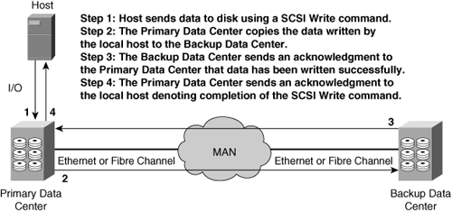
Consequently, enterprise networks are now locating new disaster-recovery sites and data centers in a MAN within 200 km to 600 km from the main campus or in more distant locations using WAN technologies. For proper data backups to occur between the main operations facility and its disaster-recovery sites, a fair amount of bandwidth at low latency is necessary for synchronous data transfers between sites. Synchronous data transfers are necessary to avoid data loss. They avoid data loss by maintaining multiple simultaneous copies of data between the main operations facility and its disaster-recovery sites. Figure 16-1 illustrates a sample method of synchronous data.
Cisco metro solutions provide enterprise customers with the following design characteristics:
High bandwidth in terms of 1 to 10 Gbps
High availability in terms of 10-ms failovers
Low latency, where latency is a factor of distance, exclusively
Scalability
Modularity
MANs also fit well into WAN environments to connect multiple remote sites at high bandwidth.
This chapter introduces, in brief, the Cisco metro solutions as applied to building Cisco multilayer switched networks at high speeds over long distances. This chapter does not discuss, as with the previous edition, tunneling options, EoMPLS, or MPLS. For a complete discussion of all Cisco metro solutions, options, and products, consult Cisco.com.
The Cisco metro solutions deliver a comprehensive multilayer service portfolio for service providers and enterprises who manage their own MAN and WAN solutions. This portfolio of metro solutions, which includes metro IP, metro Ethernet switching, metro storage transports, and metro optical transport platforms and technologies, ensures a flexible and efficient foundation for profitable metro services for service providers and high availability and scalability to the enterprise.
Moreover, the Cisco metro solutions enable service providers to grow quickly and profitably with a comprehensive multilayer service portfolio for those customers who choose to use a service provider to manage their metro solution. The metro service portfolio, achieved through a modular system, offers to service providers deployment flexibility with operational consistency across all metro environments. The Cisco modular system supports metro solutions with up to 10 Gigabit Ethernet, 2, 4, or 10 Gigabit Fibre Channel, and 10-Gbps Synchronous Optical Network/Synchronous Digital Hierarchy (SONET/SDH) OC-192. These high data rates coincide with the high-availability transport, scalability, and data integrity of the metro solution.
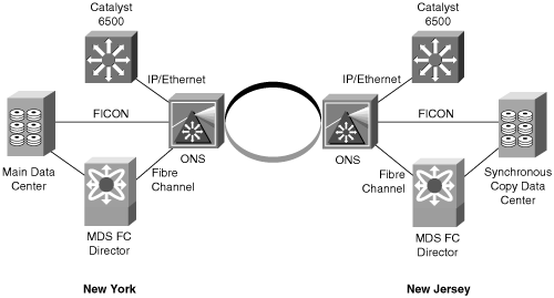
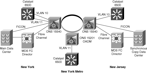
Figure 16-2 illustrates a sample Cisco metro solution. In this figure, multiple protocols, including Ethernet, Enterprise Systems Connection (ESCON), Fibre Connection (FICON), and Fibre Channel, transfer the metro solution. The metro solution in this example uses a metro optical solution for transporting data at high bandwidth and low latency. The metro optical solution uses the Cisco ONS 15540s as the optical platform and dense wavelength division multiplexing (DWDM) as the optical transport medium. Catalyst Ethernet switches connect to the Cisco ONS 15540s as a metro Ethernet (access) platform.
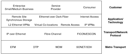
Figure 16-3 illustrates the generic metro solution hierarchy. The definitions for the acronyms and abbreviations used in the figure are as follows:
Ethernet in the first mile (EFM)
Dynamic Packet Transport (DPT)
Layer 2 Ethernet Virtual Private Networks (L2 Ethernet VPNs)
Synchronous Optical Network/Synchronous Digital Hierarchy (SONET/SDH)
Wavelength division multiplexing (WDM)
Service providers often build networks that integrate with legacy infrastructures and are flexible to respond to changing market conditions such as reduction in bandwidth costs and diverse customer requirements varying from DWDM to SONET. This is especially important when service providers provide MANs with connectivity to enterprises. As a result, Ethernet emerged as a leading access medium for enterprise MANs for the following reasons:
Enables most cost-effective services
Provides ample bandwidth between the enterprise and the metro
Eliminates access bottlenecks
Allows service providers to deliver multiple data, voice, and video services to enterprise and consumer customers over a high-speed access connection
Supports QoS
Inherits low latency of the protocol
The Cisco metro Ethernet platforms move Ethernet data from the enterprise or local network to the metro optical platform. The metro optical platforms transport the Ethernet frames to remote sites using one of the available optical transport mechanisms, such as DWDM or SONET. The following section introduces this concept of metro Ethernet. Later subsections discuss metro Ethernet over the different transports. In brief, this section discusses the following topics:
Metro Ethernet connectivity and transport
Metro Ethernet over SONET
Metro Ethernet over DWDM
Metro Ethernet over CWDM
Transmitting Ethernet packets across the MAN is applicable using a variety of methods. These methods depend on factors such as cost effectiveness, service levels, transparency, and scalability. Several options are available for sending Ethernet frames across the WAN, ranging from using point-to-point Layer 1 connections such as DWDM to more complex Layer 2 and 3 encapsulation protocols that allow Ethernet services to be emulated over packet networks such as 802.1Q-in-Q tunneling and VPN tunneling. Each option has different advantages and disadvantages. In brief, this chapter discusses the following leading enterprise methods of Layer 1 metro Ethernet connectivity:
SONET
DWDM
CWDM
This section discusses the criteria for choosing a metro Ethernet solution in general. Later sections discuss the properties of the SONET, DWDM, and CWDM metro Ethernet solutions, specifically, and their characteristics applicable to this section.
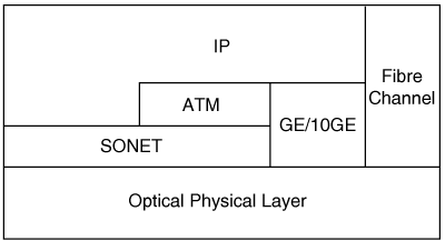
Figure 16-4 illustrates the optical and IP hierarchy for this chapter. IP runs over SONET, ATM, or Ethernet, which uses the optical transport. Fibre Channel runs directly on an optical network. Although not depicted in the figure, Fibre Channel can run on top of IP.
In brief, use the following criteria for determining the best available option for metro Ethernet connectivity in any campus design:
Cost-effectiveness—. For metro Ethernet access services to be cost-effective, the metro Ethernet access solutions must deliver network architectures of an initial low-capital expenditure with a relatively low sustaining and operation cost. For example, metro Ethernet connectivity using DWDM may have a high initial capital cost; however, the use of DWDM results in lower sustaining costs because it scales easily to accommodate growth.
Service level—. Service providers offer different levels of service for network availability, class of services, latency, and committed transfer rates. These service levels dictate the metro Ethernet connectivity solution. For instance, DWDM offers very high bandwidth connectivity with low latency compared to packet switched networks that offer low bandwidth and inherently higher latency.
Point-to-point versus multipoint—. With metro Ethernet access services, the concept of multipoint connectivity is slightly different from typical Frame Relay–like multipoint connections. Instead of the CPE supporting multiple virtual circuits (VC) over a single physical interface, there is only a single logical interface from the CPE to the provider edge (PE). At the PE, this single logical interface maps into multiple point-to-point circuits to establish a single Layer 2 broadcast domain. With this model of multipoint connectivity, it is possible, but not necessarily desirable, to eliminate the Layer 3 function on the CPE. For larger multipoint topologies, enterprises need to consider a Layer 3 method of transport, such as MPLS VPN, for security and ease-of-management purposes.
Transparency—. Because Ethernet is the predominant technology used in enterprise networks, metro Ethernet can accommodate a transparent interface to the enterprise. Because the medium is transparent, the metro solution can pass standard Ethernet frames and 802.1Q tagged frames without any modification to the frame. As a result, a Layer 2 network may span across the metro solution. This capability did not exist with traditional data-communication services such as ATM, Frame Relay, or leased lines. Layer 2 transport protocols were different from the Ethernet Layer 2 protocol used in the enterprise’s LAN. The different transport protocol forced Layer 3 interfaces between the enterprise and service provider.
Scalability—. As the name suggests, metro Ethernet access services originated to provide high-speed connectivity within a metro service area. However, as metro Ethernet access services evolved, enterprises desired an Ethernet service interface that connects the enterprise to the service provider for general-purpose WAN connectivity to either private or public networks. Some service providers choose to offer metro Ethernet services to a specific metropolitan area, such as the New York City area. Other service providers choose to scale metro Ethernet services to inter-metro distances, such as the New York City metro area to include New Jersey. In either case, the control plane must allow new metro access and aggregation network elements to connect into the core metro network without major disruption or reconfiguration.
Two types of metro Ethernet connectivity options, transparent LAN services and directed VLAN services, determine frame handling as the frame passes through the center of the metro network. With a transparent LAN service, the metro solution forwards traffic as a multipoint-to-multipoint connection, whereas all connected sites in the metro solution see all traffic. With directed VLAN service, the metro solution forwards the traffic according to the campus VLAN topology. The next two sections discuss transparent and directed LAN services in more detail.
Transparent LAN service (TLS) refers to adjoining multiple sites over a metro solution using a single subnet or VLAN. TLS is easy to implement but presents scalability issues and a single failure domain for all customers using the metro solution. TLS supports point-to-point and point-to-multipoint operation.
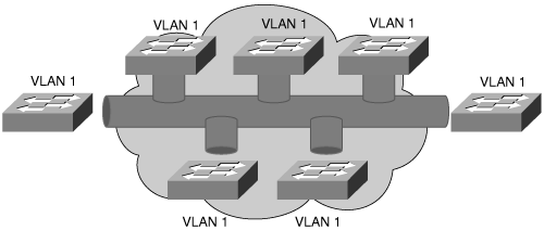
In a transparent LAN service, data transmitted across the metro solution acts in a manner similar to an Ethernet hub using a single broadcast domain. This type of behavior presents a single failure domain to all customers of the metro solution. One traffic flow from a single customer within the core network of the metro solution may affect traffic from another customer. Figure 16-5 illustrates a TLS metro solution where the metro solution acts as a single broadcast domain.
For the enterprise using a TLS metro solution, all of its routers and multilayer switches reside on the same subnet on the edge. The service provider easily provides a TLS solution for the enterprise by maintaining the same VLAN across its entire infrastructure. However, a TLS metro solution has two potentially serious performance implications for the enterprise:
Broadcasts are sent to all sites that connect to the TLS metro solution.
All routers must peer with each other across the MAN, which may cause a scalability problem for routers that maintain large routing tables. Multipoint solutions where remote site routers only peer with a central site tend to scale better than fully meshed networks where all remote site routers peer with each other.
The key benefit of TLS is that its shared backbone provides simplicity of implementation. All remote locations appear on a single subnet and in a single VLAN. Service providers and enterprise customers use VLANs to segment and differentiate traffic across a TLS metro solution. However, from a service provider standpoint, only 4096 individual VLANs are available for customer use. Generally, 4096 VLANs are insufficient for service providers who provide multiple VLANs on metro Ethernet solutions to multiple customers. In addition, supporting multicast and implementing QoS on TLS metro solutions is difficult because no discrete method of traffic separation exists.
In summary, only enterprises that purchase their own dark fiber and implement their own metro solution platforms use the TLS design, with or without the use of VLANs. Generally, service providers use directed VLAN services, as discussed in the next section, to take advantage of the cable plant while maintaining differentiated and autonomous metro Ethernet solutions to enterprise customers.
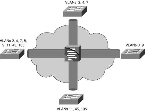
In a directed VLAN service (DVS), the metro solution uses VLAN IDs to forward traffic to select destinations. DVS supports both point-to-point and point-to-multipoint operations. Typically, DVS isolates VLANs of the enterprise from the VLANs of the network by using additional header information. As such, enterprise VLANs are separate from the metro VLANs. One such example is to add a second 802.1Q header to a frame to achieve a Q-in-Q transport.
The switch in the core sees the VLANs defined at the edge of the network and provides VLAN switching. Note that these VLANs are not the VLANs configured in the multilayer switched network, but rather VLANs locally significant only to the metro solution. In DVS, the core switch must know the enterprise VLAN assignments. This implementation requires Per VLAN Spanning Tree Plus (PVST+).
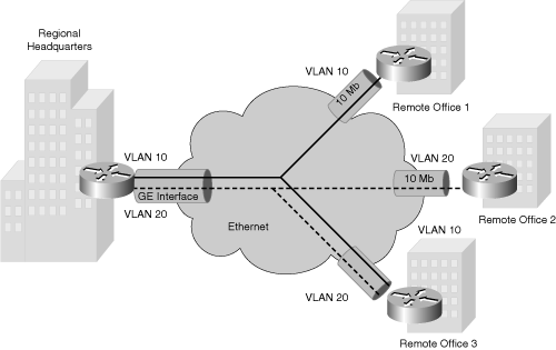
DVS allows enterprises to support VLANs that appear in multiple locations across the core. In Figure 16-7, VLAN 10 appears in Remote Offices 1 and 3, whereas VLAN 20 appears in remote offices 2 and 3. The core switch in the cloud, generally physically located in Enterprise Edge of the Campus network, provides VLAN switching capability. As a result, the core switch knows about VLAN assignments on the remote location switches.
Irrespective of the connectivity method, TLS or DVS, the metro solutions move Ethernet frames across a metro optical platform using several transports. One such transport is SONET.
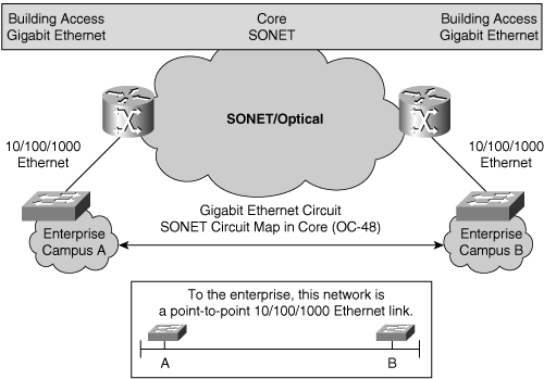
SONET standards specified in ANSI T1.105, ANSI T1.106, and ANSI T1.117 define optical signals and a synchronous frame structure for multiplexed digital traffic. SONET carries numerous signals of different capacities through a synchronous, flexible, optical hierarchy. From the perspective of metro Ethernet over SONET, the SONET network is completely transparent. Figure 16-8 illustrates a sample network topology using SONET on OC-48 as a metro Ethernet solution.
Note
SDH, founded in Europe by the International Telecommunication Union Telecommunication Standardization Sector (ITU-T), is a similar synchronous framing standard and is regarded as equivalent to SONET. North American service providers generally use SONET while the rest of the world uses SDH.
Because of its history in legacy telephony networks, service providers leverage well-established and entrenched SONET infrastructures for MAN deployments. Metro Ethernet over SONET takes advantage of the management and fault-tolerance mechanisms of this widely deployed SONET technology. Specifically, SONET supports up to a 50-millisecond internal failover. In addition, SONET uses a byte-interleaved multiplexing scheme for increasing bandwidth. Byte-interleaving simplifies multiplexing and presents end-to-end network management capability.
The base signal of SONET is the synchronous transport signal–level 1 (STS-1); this signal operates at 51.84 Mbps. SONET supports a hierarchy of signaling speeds by interleaving multiple STS-1 signals. Table 16-1 illustrates the hierarchical signaling speeds for SONET. In Table 16-1, the term OC refers to the optical carrier. Typically, service providers refer to the SONET signaling speeds in terms of the OC speeds, such as OC-48.
As illustrated in Table 16-1, SONET multiplexes several lower-speed signals together to achieve higher-level signals. For example, 12 STS-1 signals multiplex together to form an STS-12 (OC-12) signal. In addition, note that 10 Gigabit Ethernet operates at a rate that maps directly into OC-192.
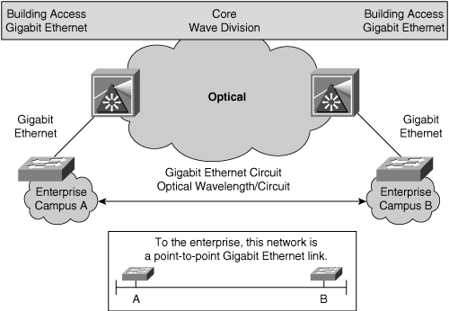
Figure 16-8 also illustrates the transparency of using SONET as a metro solution. In this figure, the SONET metro Ethernet network appears to the end user as a point-to-point Gigabit Ethernet link. The metro Ethernet system essentially creates a long extension cord for the Gigabit Ethernet transmission between enterprise campus A and enterprise campus B. In this figure, the metro solution connects in the Building Access submodule of the Enterprise Edge submodule. Connecting submodules to the SONET network requires the use of Catalyst switches or Cisco IOS routers with specific port adapters and interfaces in the service provider network.
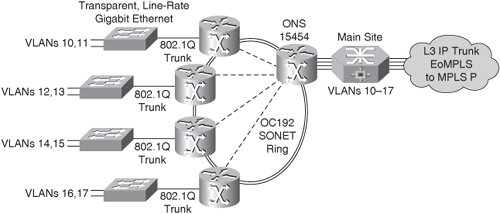
Figure 16-9 illustrates a sample network topology using SONET. The figure demonstrates how to configure a metro Ethernet solution using a SONET ring infrastructure. The Cisco ONS 15454 provides support for both Ethernet and SONET/SDH interfaces, allowing enterprises to build metro-to-metro or city-to-city metro Gigabit Ethernet networks.
In addition, the ONS 15454 supports port-based VLANs that group ports into virtual workgroups. These port-based VLANs ensure that Ethernet ports see only traffic from ports within the same VLAN. The different VLANs communicate with each other through a router that spans multiple VLANs by using router ports in each VLAN, or through a router that understands IEEE 802.1Q. In Figure 16-9, the main site uses a router capable of IEEE 802.1Q routing.
SONET encompasses far more technical detail than the information provided in this chapter. For additional information on SONET, refer to the following document on Cisco.com:
“A Brief Overview of SONET Technology,” Document ID: 13567 http://www.cisco.com/en/us/tech/tk482/tk607/technologiestechnote09186a0080094313.shtml
In brief, SONET offers several advantages to a metro Ethernet solution. These advantages are as follows:
Internal 50-ms failover mechanism through protection switching
Support for management and alarms natively
Generally available in metro areas for reasonable cost
Conversely, SONET has its disadvantages. A summary of its disadvantages is as follows:
Available only in bandwidth increments of 51.84 Mbps
Core equipment is costly where existing equipment is not available
Redundant circuits are generally idle and do not take advantage of additional resources
Not able to statistically multiplex traffic across its backbone to increase available bandwidth of circuit
Choosing SONET as part of a metro solution requires careful consideration, planning, and availability of SONET through service providers.
Metro Ethernet over WDM solutions are metro implementation options that provide 1-, 2-, and 10-Gbps rates with ease of configuration, high scalability, transparency, and optical protection. WDM technology over long distances for ultra-high-bandwidth transports is becoming increasing popular. The scalability of WDM solutions for long-distance, high-bandwidth requirements versus the laying of additional fibers is tremendous and results in significant cost savings. WDM achieves the same effects of multiple strands of fiber by offering multiple channels for discrete isolation of network traffic. At a high-level overview, WDM maps multiple optical signals to individual wavelengths and multiplexes the wavelengths over a single fiber. This multiplexing achieves multiple distinct optical paths across a single pair of fiber. This section discusses the two variations of WDM solutions available on Cisco platforms:
Metro Ethernet over DWDM
Metro Ethernet over coarse wavelength division multiplexing (CWDM)
At a high-level overview, DWDM provides a transparent medium for Ethernet connectivity similar to SONET. In Figure 16-10, the DWDM metro Ethernet network appears to the end user as a point-to-point Gigabit Ethernet link. As with SONET, the metro Ethernet system essentially creates a long extension cord for the Gigabit Ethernet transmission between enterprise campus A and enterprise campus B.
At Layer 1, DWDM converts Ethernet packets on a bit-by-bit basis into an optical stream at 1, 2, or 10 Gbps. DWDM does not perform framing conversion and simply performs optical conversion. As a result, Ethernet over DWDM does not require specific encapsulation. The core network moves data bits transparently from campus to campus. Because DWDM simply converts data bits to an optical stream, DWDM suffices as a transport media for not only Ethernet, but also storage protocols such as Fibre Channel, FICON, and ESCON.
Figure 16-11 illustrates a sample deployment of DWDM for multiple protocols and autonomous networks.
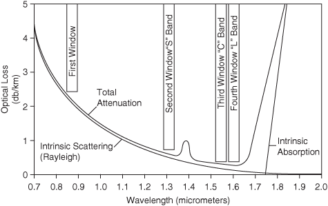
The two most commonly used wavelength regions for optical transmission over long distances are 1310 nanometers (nm) and 1550 nm. Short distance requirements commonly use the 850-nm window. These 1310-nm (S band) and 1550-nm (C band) windows, along with a fourth window at 1625 nm (L band) for upcoming technologies, have significantly lower optical loss compared to other windows near the same wavelength range. Figure 16-12 illustrates the optical loss characteristics at different wavelengths.
Transmissions using the 1310-nm wavelength (band) are popular for metropolitan or short-range applications because of their relatively low cost. The 1310-nm single-mode GBICs are readily available for Catalyst switches. Because transmissions in the 1550-nm band can travel greater distances because of that band’s intrinsic properties, the 1550-nm range is preferable for very long-distance transmissions (between 100 km and 600 km). The increased cost in CPE equipment to process wavelengths in the 1550-nm range is still cheaper than the aggregate cost associated with continuous retransmission of a 1310-nm range optical signal. Figure 16-13 illustrates these windows relative to the electromagnetic spectrum.
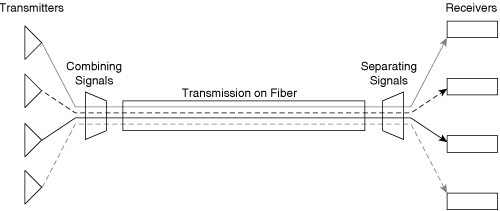
DWDM technology assigns incoming optical signals to specific frequencies of light (wavelengths, or lambdas) within the 1550-nm frequency band. Figure 16-14 illustrates the principle of multiplexing different wavelengths across a single medium.
This multiplexing closely resembles the way radio stations broadcast on different wavelengths without interfering with each other. Because each channel transmits at a different frequency, a tuner is necessary to select the desired channel.
Note
This chapter uses the term wavelength instead of the term frequency to avoid confusion with other uses of frequency. The term lambda and wavelength are interchangeable and relate to Layer 1 optical functionality. Channel describes a Layer 2 (Ethernet, Fibre Channel) link mapping onto a wavelength. A single wavelength can carry multiple channels in the form of an Ethernet trunk channel, or an EtherChannel.
Current models of the Cisco optical platforms support up to 32 usable lambdas plus a 33rd lambda for management. DWDM optical platforms use different frequencies and wavelengths of the ITU draft standard G.692 for systems based on 100-GHz wavelength spacing with a center wavelength at 1553.52 nm. Table 16-2 illustrates the ITU grid for these types of DWDM systems.
Table 16-2. ITU Grid
ITU Grid Frequency (THz) | Wavelength (nm) | Frequency (THz) | Wavelength (nm) | Frequency (THz) | Wavelength (nm) |
|---|---|---|---|---|---|
196.1 | 1528.77 | 194.6 | 1540.56 | 193.1 | 1552.52 |
196.0 | 1529.55 | 194.5 | 1541.35 | 193.0 | 1553.33 |
195.9 | 1530.33 | 194.4 | 1542.14 | 192.9 | 1554.13 |
195.8 | 1531.12 | 194.3 | 1542.94 | 195.8 | 1554.94 |
195.7 | 1531.9 | 194.2 | 1543.73 | 192.7 | 1555.75 |
195.6 | 1532.68 | 194.1 | 1544.53 | 192.6 | 1556.56 |
195.5 | 1533.47 | 194.0 | 1545.32 | 195.5 | 1557.36 |
195.4 | 1534.25 | 193.9 | 1546.12 | 192.4 | 1558.17 |
195.3 | 1535.04 | 193.8 | 1546.92 | 192.3 | 1558.98 |
195.2 | 1535.82 | 193.7 | 1547.72 | 192.2 | 1559.79 |
195.1 | 1536.61 | 193.6 | 1548.51 | 192.1 | 1560.61 |
195.0 | 1537.40 | 193.5 | 1549.32 | 192.0 | 1561.42 |
194.9 | 1538.19 | 192.4 | 1550.12 | 191.9 | 1562.23 |
194.8 | 1538.98 | 193.3 | 1550.92 | 191.8 | 1563.05 |
194.7 | 1539.77 | 193.2 | 1551.72 | 191.7 | 1563.86 |
As mentioned previously, most LAN-based Cisco IOS routers and Catalyst switches use either the 850-nm band or the 1310-nm band for optical transmission. For a DWDM system to transmit a signal in the 1550-nm range, it converts the ingress 850- or 1310-nm signal into a 1550-nm signal using a device called a transponder. Transponders accomplish the wavelength altering by doing an optical-to-electric-to-optical (OEO) conversion. In addition, transponders support regeneration, reshaping, and retiming functionality.
DWDM systems use optical multiplexers and de-multiplexers to combine and separate the multiple wavelengths for transmission and upon reception of optical signals, respectively. Optical amplifiers increase optical signals as they transmit across the optical fiber. Optical amplifiers differ from traditional amplifiers in that the optical signals are not converted to electrical signals for amplification. Erbium doped fiber amplifiers (EDFA) are the most commonly used optical amplifier in today’s DWDM system.
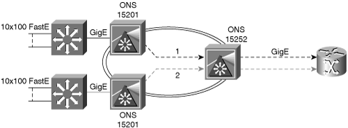
Furthermore, DWDM systems use optical add/drop multiplexers (OADM) to drop or add a single lambda at a specific location. OADMs are useful in aggregating remote sites where each remote site uses only a subset of lambdas. For instance, Figure 16-15 illustrates the use of an OADM. In this DWDM system, the New York metro site only uses one lambda. As a result, the DWDM topology uses an OADM to add and drop a single lambda at this location.
This section is meant to be only a brief overview of DWDM; for a complete understanding of DWDM, consult Cisco.com.
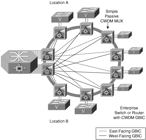
CWDM technology harnesses the same WDM technologies as DWDM systems. DWDM and CDWM primarily differ in distance ranges, spacing of lambdas, number of channels, and the ability to amplify optical signals. In brief, CDWM uses 8 lambdas using a 20-nm wavelength grid, whereas DWDM technology has 32 or more lambdas using a 1-nm wavelength grid. CWDM technology does allow for optical signal amplification using any external amplifier, which limits its capability to transmit under 100 Km. CWDM basically provides for the same topology as DWDM except the Cisco IOS routers or Catalyst switches originate the signal and OADMs add or drop lambdas at a specific location. As such, CWDM is far less complex than DWDM, requires less hardware, and is easier to install. Figure 16-16 illustrates a sample metro Ethernet over CDWM topology.
The CDWM solution uses two main components:
CWDM GBIC modules—. The Cisco CWDM GBICs convert Gigabit Ethernet electrical signals into optical signals at a specified wavelength (color). As a result, these GBICs are available in a variety of colors, including the 1470, 1490, 1510, 1530, 1550, 1570, 1590, and 1610 nm wavelengths.
CWDM OADM modules—. The Cisco CWDM OADMs are passive devices that provide the ability to multiplex/de-multiplex or add/drop wavelengths from multiple fibers onto one fiber. The OADM connects directly to the color-matching Cisco CWDM GBICs.
CWDM does support EtherChannel using multiple CWDM GBICs and OADM modules between sites. An alternative to EtherChannel is using multiple Layer 3 equal-cost paths over multiple CWDM connections. In summary, CWDM has the following benefits as a metro Ethernet solution:
Metro distance range of approximately 100 km
Inexpensive compared to DWDM
Viable alternative to 10 Gigabit Ethernet over DWDM using EtherChannel over CWDM
The Catalyst 6500, 4500, 4000, 3550, and 2950 families of switches support CWDM GBICs
Cisco MDS Fibre Channel switches support CWDM GBICs
The only main downside to deploying CWDM as a metro solution is distance; CWDM does not support amplification, which limits distances to 100 km for 30-dB optical budgets.
Several factors limit distances of unamplified optical fiber transmission. The root cause of these challenges is the transmission of light in optical fiber. These challenges can be summarized into one of the following three categories:
Attenuation—. Attenuation is the loss of light pulses as the pulses travel down the fiber. Attenuation is a factor of internal and external properties such as scattering, absorption, physical bending, and other environmental properties. If there is too much attenuation in an optical cable between a transmitter and receiver, the receiver may not be able to decode the optical pattern, rendering the fiber plant useless or problematic depending on the level of attenuation.
Dispersion—. Dispersion is the spreading of light pulses as the pulses travel down the optical fiber. Figure 16-17 illustrates dispersion. Two main types of dispersion affect optical systems: chromatic dispersion, which is linear, and polarization mode dispersion (PMD), which is nonlinear. Chromatic dispersion is related only to the wavelength of the optical signal. For a given fiber type and wavelength, the spectral line width of the transmitter and the bit rate of the laser determine the chromatic dispersion tolerance of a system. PMD has essentially the same effect on the system performance as chromatic dispersion, which causes errors in the optical signal. However, PMD has a different origin from chromatic dispersion; PMD occurs when different polarization states propagate through the fiber at slightly different velocities. PMD is a major concern for 10 Gbps and greater transmission speeds. Dispersion in optical fibers may make optical signals unreadable at receivers, rendering fiber plants useless or problematic. Dispersion is a factor of wavelength and distance, as illustrated in Figure 16-17. Cisco optical products adhere to specific dispersion characteristics and design guides.
Note
In reference to optical fibers, multimode fiber generally suffers from chromatic dispersion that can be compensated with dispersion-shifted fiber that uses a graduated index of reflection between the core and cladding. Multimode fiber also suffers from multimodal dispersion where many paths at varying lengths exist in the fiber, resulting in light photons spreading out over time where some light photons take faster paths while the others take slower paths. Conversely, single-mode fiber mainly suffers from PMD and is affected by chromatic dispersion when using physically dirty lasers.
Nonlinearities—. Nonlinear properties of the optical fiber lead to transmission effects that further degrade the optical signal over long distances. For more information on nonlinear properties, refer to Cisco.com and other texts regarding fiber optics.
All these issues are critical criteria for designing optical networks, especially those exceeding 100 km. This section discusses these optical characteristics only in brief; consult Cisco.com for additional design guides, fiber budget documentation, and Cisco optical product limitations.
This chapter introduced several metro Ethernet solutions, covering specifically deploying metro Ethernet over optical solutions such as CDWM, DWDM, and SONET.
The information in this chapter can be summarized as follows:
Cisco metro Ethernet solutions provide high bandwidth and low latency Ethernet and Fibre Channel connectivity options.
Current design requirements and recommendations for disaster-recovery planning require high bandwidth with low latency connectivity between enterprise sites and campuses.
Enterprises choose whether to implement their own metro solution by purchasing dark fiber or purchasing Ethernet ports from service providers.
The Cisco wide range of optical and Catalyst switching products fits into various metro Ethernet solutions depending on specific application.
Metro Ethernet and Fibre Channel solutions using SONET, DWDM, and CDWM are high-bandwidth options available with Cisco optical platforms.
TLS solutions forward traffic to all interfaces in the topology, whereas DVS solutions switch traffic, transparently to the enterprise, to specific interfaces.
Metro solutions using SONET are widely available from service providers and support high availability.
Metro solutions using DWDM are highly scalable and offer extremely high performance compared to metro solutions using SONET.
Metro solutions using CDWM offer similar benefits to metro solutions using DWDM at a lower cost, but they do not support the long-range distances (in excess of 100 km) of DWDM.
For multiple-choice questions, there might be more than one correct answer.

