Chapter 10
Grabbing Onto Object Selection
IN THIS CHAPTER
![]() Using command-first editing
Using command-first editing
![]() Selecting objects with maximum flexibility
Selecting objects with maximum flexibility
![]() Editing with grips
Editing with grips
Editing objects is the flip side of creating them, and in AutoCAD, you usually spend more time editing than drawing objects from scratch. That’s partly because the design and drafting process is, by its nature, subject to changes, and also because AutoCAD lets you easily edit objects cleanly.
Creating an object and then editing it can also be faster than doing it correctly the first time. In particular, placing a circle and then breaking or trimming it is often faster than fighting your way through all the Arc command’s options.
 Specifying precise locations and distances is as vital to editing objects in AutoCAD as it is to creating them. Become familiar with the precision techniques described in Chapter 8 before you apply the editing techniques described in this chapter to drawings.
Commanding and Selecting
AutoCAD offers three styles of editing:
- Command-first
- Selection-first
- Direct-object (grip)
AutoCAD refers to command-first editing as verb-noun editing and to selection-first editing as noun-verb editing. When you see this terminology in the Options dialog box or the online Help system, for example, don’t worry — you haven’t dropped back into fifth grade English class!
Command-first editing
In command-first editing, you start a command and then select the objects on which the command works. This method is also the only way to use certain editing commands (such as Fillet and BReak). It’s no surprise that command-first editing is the traditional editing style in AutoCAD, and the one you should be the most comfortable using.
Selection-first editing
In selection-first editing, you perform the same steps — in the same order — as in most Windows applications: Select the object first, and then choose the command. Some people claim that selection-first editing tends to be easier to master and makes AutoCAD more approachable if you’re a new or an occasional user.
Direct-object manipulation
In direct-object manipulation, you perform common editing operations by using the mouse to grab the selected object and perform an action on it, such as moving all or part of it to a different place in the drawing. No named command is involved; the act of moving the mouse and clicking the mouse buttons in certain ways completes the editing changes. AutoCAD supports direct-object manipulation via the powerful technique called grip-editing. Grips are the little square, rectangular, or triangular handles that appear on an object when you select it. You can use grips to stretch, move, copy, rotate, scale, or otherwise edit the object. I discuss grip-editing in Chapter 11.
Choosing an editing style
This book emphasizes command-first editing, but I also discuss grip-editing in Chapter 11. AutoCAD, in its heart of hearts, is a command-first program. In fact, it started out offering only command-first editing and later added selection-first methods; current releases of AutoCAD inherit this ancestral trait. I stress command-first editing for these reasons:
- Longevity: It’s the oldest editing style in AutoCAD, and the one with which experienced AutoCAD users are most familiar.
- Naturalness: Would you say, “I want to eat my lunch”? or “My lunch I want to eat”? Okay, so Yoda might say, “Eat my lunch I want to!”
- Consistency: It works consistently with all editing commands — some editing commands remain command-first only.
- Flexibility: It provides added object selection flexibility, which is useful when you work on complicated, busy drawings.
After you know how to do command-first editing, you can simply reverse the order of many editing operations to perform them in selection-first style instead. But if you don’t become familiar with command-first editing in the beginning, you’ll be bewildered by a few useful AutoCAD commands that work only in the command-first style; commands such as these ignore any already selected objects and prompt you to select objects before you can continue.
Much of the information in the rest of this book assumes that you’re using the default AutoCAD selection settings. If you find that object selection or grip-editing is working differently from the way it’s described in this chapter, click the Application button, click Options from the bottom of the Application menu to open the Options dialog box, and then check the settings on the Selection tab. The following check box settings should be selected (as shown in Figure 10-1), and all other check box settings should be deselected:
- Noun/Verb Selection
- Object Grouping
- Implied Windowing
- Allow press and drag for Lasso
- Show Grips
- Show Grip Tips
- Show Dynamic Grip Menu
- Allow Ctrl+Cycling Behavior
- Show Single Grip on Groups
- Show Bounding Box on Groups
- Selection Preview when a Command Is Active
- Selection Preview when No Command Is Active
- Command Preview
- Property Preview
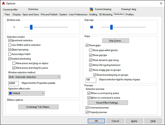
FIGURE 10-1: Setting selection options in the Options dialog box.
 For information on what these options do, hover the mouse pointer over an option to display a tooltip with information from the online Help system.
Selecting Objects
Part of AutoCAD’s editing flexibility comes from its object-selection flexibility. For example, command-first editing offers 16 selection modes! I describe the most useful ones in this chapter. Don’t worry, though: You can squeak by most of the time using only three selection modes, each of which I describe in this section:
- Select a single object by picking it.
- Select multiple objects by enclosing them in a window selection box or polygon.
- Select multiple objects by enclosing them in a crossing selection box or polygon.
One-by-one selection
The most obvious way to select objects is to pick (by clicking) them one at a time. Objects (even just one) that are selected and ready for editing are called a selection set. You can build a selection set cumulatively by using this pick-one-object-at-a-time selection mode, but this cumulative convention may be different from the one you’re used to. In most Windows programs, if you select one object and then another, the first object is deselected, and the second one is selected; only the object you select last remains selected. In AutoCAD, all objects you select, one at a time, remain selected and are added to the selection set, no matter how many objects you pick. Most editing commands affect the entire group of selected objects.
Selection boxes left and right
Selecting objects one at a time works well when you want to edit a small number of objects, but many CAD editing tasks involve editing lots of objects. Do you really want to pick 132 lines, arcs, and circles, one at a time? Okay, maybe you do if you’re paid by the hour, but after a while your company won’t be able to afford you.
Like most Windows graphics programs, AutoCAD provides a selection window feature for grabbing a bunch of objects in a rectangular area. As you may guess, the AutoCAD version of this feature is a bit more powerful than the similar feature in other Windows graphics programs. AutoCAD calls its version implied windowing. Here’s how you use it:
- Window object selection: When you click a blank area of the drawing (not on an object), you’re indicating that you want to specify a selection by dragging a window around the objects. If you move the cursor to the right before picking the next corner of the selection area, you’re further implying that you want to select all objects that reside completely within the selection area.
- Crossing object selection: When you click a blank area of the drawing (not on an object), you’re indicating that you want to specify a selection by dragging a window around and through the objects. If you move the cursor to the left before picking the next corner of the selection area, you’re indicating that you want to select all objects that reside completely within or touch or cross the selection area boundary.
Fortunately, AutoCAD gives you visual cues that there’s a difference. As you move to the right, the window area appears as a rectangular or polygonal area with a blue fill and a solid border. As you move to the left, the crossing area appears as a rectangle or polygon with green fill and a dashed border.
If your editing method of preference is selection-first, AutoCAD gives you the option to drag a polygonal window or crossing area or to simply drag a series of lines through the objects you want to select. Simply click a point and then type the appropriate alias at the command line to initiate the Fence, WPolygon, or CPolygon option.
Figures 10-2 and 10-3 show a window box and a crossing box, respectively, in action.
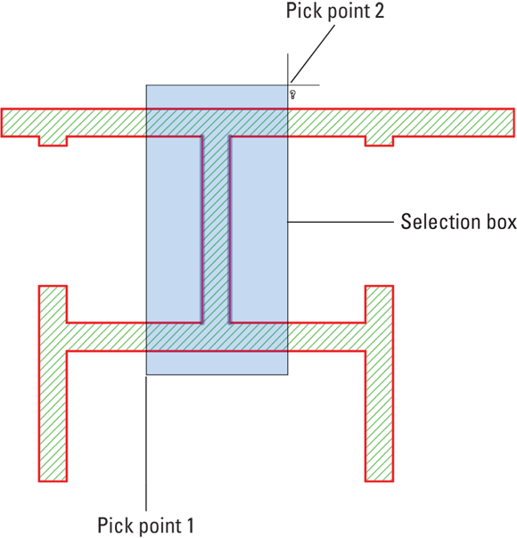
FIGURE 10-2: A window selection box, drawn from left to right, selects only the two objects (the two vertical lines) that are completely within the box.

FIGURE 10-3: A crossing selection box, drawn from right to left, selects 11 objects that are completely or partially within the box.
Tying up object selection
AutoCAD 2015 added another selection mode called lasso. As with the other modes, lasso isn’t a specific command but is initiated based on how you manipulate the mouse. The window modes are initiated when you click two different points. To initiate lassoing, on the other hand, move the mouse to a desired starting point, and then press and hold down the left mouse button. Continue to hold down the left mouse button as you move the cursor, creating a lasso trail around and among drawing objects. When you release the left button, the trail automatically closes itself back to the start point, the trail disappears, and all the lassoed objects become selected.
After you initiate lassoing, your first mouse movement dictates whether the lasso is a crossing lasso or a window lasso. If your first movement is to the right, it’s a window lasso. If your first mouse movement is to the left, it’s a crossing lasso.
You can mix and match, selecting individual objects, specifying a window box, specifying a crossing box, and lassoing. Each selection adds to the current selection set, allowing you to build an enormously complicated selection of objects and then operate on them with one or more editing commands.
 Before the mid-2017 release of AutoCAD, if you pan while window selecting, anything in the window that is panned off-screen is dropped from the selection set.
You can press Shift in combination with any of the four standard selection modes — single object, window area, crossing are, and lasso — to remove already selected objects from the selection set. This feature is especially useful when you’re building a selection set in a crowded drawing; you can select a big batch of objects by using Window or Crossing and then holding down Shift while selecting to remove the objects that you want to exclude from the editing operation. You can carve a statue of an elephant the same way by starting with a big block of marble and cutting off anything that doesn’t look like an elephant.
Perfecting Selecting
When you edit in command-first mode, you have all the selection options described in the earlier section “Selecting Objects” — single object, window box, window polygon, crossing polygon, and crossing box — plus a slew of others. If you type ? and press Enter at any Select objects prompt, AutoCAD lists all the selection options at the command line:
Window/Last/Crossing/BOX/ALL/Fence/WPolygon/CPolygon/Group/Add/Remove/Multiple/Previous/Undo/AUto/SIngle/SUbobject/Object
Table 10-1 summarizes the most useful command-first selection options.
TABLE 10-1 Useful Command-First Selection Options
|
Option |
Objects That It Selects |
|
Window |
All objects completely within a rectangular area that you specify by picking two points |
|
Crossing |
All objects within, crossing, or touching a rectangular area that you specify by picking two points |
|
WPolygon |
All objects completely within a polygonal area whose corners you specify by picking points |
|
CPolygon |
All objects within, crossing, or touching a polygonal area whose corners you specify by picking points |
|
Fence |
All objects touching an imaginary polyline whose vertices you specify by picking points |
|
Last |
The last object you drew (whether or not it’s visible in the display) |
|
Previous |
The previous selection set that you specified |
|
ALL |
All objects on layers that aren’t frozen or locked and that are in the current space (model space or paper space), including objects that aren’t displayed because you’ve zoomed in |
To use any command-first selection options at the Select objects prompt, type the uppercase letters (see Table 10-1) that correspond to the option you want, and then press Enter. Select the objects, and press Enter again to tell AutoCAD that you finished selecting objects and you want to start the editing operation.
After you finish selecting objects, you must press Enter to tell AutoCAD that you want to start the editing operation. Say … is there an echo in here? As a matter of fact, I am repeating myself. Many new AutoCAD users find it difficult to remember the necessity of pressing Enter after they finish selecting objects.
The selection preview features in AutoCAD remove a lot of doubt about which objects you’re selecting. Rollover highlighting displays individual objects with a thick, dashed lineweight as you move the cursor over them. Area selection displays a transparent, colored highlight over multiple selections when you use Window and Crossing options.
The following steps show you how to use the Erase command in command-first mode with several different selection options. The selection techniques used in this example apply to most AutoCAD editing commands:
-
Open a drawing that contains objects, or start a new drawing and create lines, arcs, or circles.
Don’t be too particular in drawing them because you blow them away in this step list.
-
Press Esc to make sure that no command is active and no objects are selected.
If any objects are selected when you start an editing command, the command, in most cases, operates on those objects (selection-first editing) instead of prompting you to select objects (command-first editing). For the reasons I describe in the section “Commanding and Selecting” earlier in this chapter, I recommend using the command-first editing style until you’re thoroughly familiar with it. Later, you can experiment with selection-first editing, if you like. Just reverse the sequence of commanding and selecting. -
 Click the Erase button in the Modify panel on the Home tab.
AutoCAD displays the
Select objectsprompt at the command line, and if dynamic input is enabled on the status bar, the Dynamic Input tooltip. -
Select two or three individual objects by clicking each one.
AutoCAD adds each object to the selection set. All the objects you select remain highlighted, and AutoCAD continues to display the
Select objectsprompt. -
Specify a window selection box that completely encloses several objects.
Move the cursor to a point below and to the left of the objects, click, release the mouse button, move the cursor above and to the right of the objects, and click again.
All objects that are completely within the box are selected.
-
Specify a crossing selection box that completely encloses a few objects and cuts through several others.
Move the cursor to a point below and to the right of some objects, click, release the mouse button, move the cursor above and to the left of some of the objects, and click and release again.
All objects that are completely within, crossing through, or touching the box are selected. AutoCAD continues to display the
Select objectsprompt. -
Type WP and press Enter to activate the WPolygon (Window Polygon) selection option.
AutoCAD prompts you to pick points that define the selection polygon.
-
Pick a series of points and press Enter.
Figure 10-4 shows an example. After you press Enter, AutoCAD selects all objects that are completely within the polygon. AutoCAD continues to display the
Select objectsprompt until you press Enter. -
Press Enter to end object selection.
AutoCAD erases all selected objects and returns to an empty command prompt.
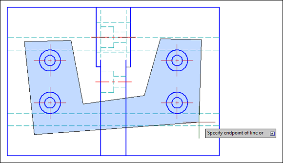
FIGURE 10-4: Lassoing objects by using WPolygon selects the concentric circles and their center lines.
Did you notice how you can use a combination of object selection methods to build a selection set and then press Enter to execute the command on the selected objects? Most AutoCAD editing commands work this way in command-first mode.
If after erasing a selection set, you immediately realize that you didn’t mean to do away with so many objects, click the Undo command or button on the Quick Access toolbar to restore them all. But AutoCAD has one additional unerase trick up its sleeve — the aptly named OOPS command. When you type OOPS and press Enter, AutoCAD restores the last selection set that you erased — even if you’ve run other commands after Erase.
The Erase command isn’t the only way to remove unwanted objects from the drawing. The easiest method in any workspace is to select an item and then press the Delete key on the keyboard.
Drawing objects on top of other objects is all too easy to do, and after you’ve done so, recognizing that multiples exist so you can weed out the ones you don’t want is pretty well impossible. When Selection Cycling is enabled on the status bar, AutoCAD displays a white, overlapping-rectangles icon if it detects multiple objects under the cursor. When you pick an object with this icon displayed, AutoCAD opens a Selection dialog box where you can choose the object you want.
AutoCAD Groupies
AutoCAD lets you select a bunch of objects and gather them into a group so that when you click one object, everything in the group is selected. You simply select objects and click Group on the Groups panel of the Home tab. If you want, you can name the group as you create it. The buttons on the main Groups panel let you create new groups, toggle group selection off and on, edit groups by adding or removing individual objects, or permanently ungroup a selected group.
Object Selection: Now You See It …
The many object-selection modes that I describe in earlier sections — and some that I don’t even describe, such as the FIlter command (check out the online Help system for more on that topic) — are useful as far as they go.
AutoCAD lets you control the visibility of individual objects, which is a big deal. Before AutoCAD 2011, the only way to control the display of objects was to turn off or freeze the layer on which they resided. If the layer held other objects that you did want to see — too bad. These three commands turn this limitation into ancient history:
- HIDEOBJECTS: Prompts you to select the objects that you want to make temporarily disappear
- ISOLATEobjects: Prompts you to select the objects that you want to see while temporarily making everything else disappear
- UNISOLATEobjects: Ends the hiding and isolating of objects
The primary method of invoking these commands is via the right-click menu. Using either command-first or selection-first editing as described in the section “Commanding and Selecting,” earlier in this chapter, simply right-click and you see the Isolate item, shown in Figure 10-5. A status bar icon — a lightbulb at the lower-right corner of the display — is dimmed when objects are either hidden or isolated. Click this icon to open a menu that lets you turn off the hiding or isolating.
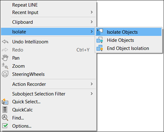
FIGURE 10-5: Making selected objects disappear, but only temporarily!
If you’re worried about the possible implications of this concept (“Hmm. I was sure I added those center lines. Do I need to add them again?”), relax. Hiding and isolating objects is temporary — it lasts only as long as the current drawing session. If you end a drawing with objects isolated or hidden, they reappear when you reopen the file.
Rumor has it that the Autodesk programmers stole this cloaking-and-uncloaking concept from the Romulans.