Chapter 22
From Drawings to Models
IN THIS CHAPTER
![]() Understanding pros and cons of three-dimensional modeling
Understanding pros and cons of three-dimensional modeling
![]() Setting up a 3D working environment
Setting up a 3D working environment
![]() Creating 3D solid geometry
Creating 3D solid geometry
![]() Editing 3D models
Editing 3D models
For millennia, people have documented the design and construction of three-dimensional objects by drawing two-dimensional views of them. Most people have continued to use these classical methods in CAD drafting because the methods are well understood and work reasonably well. After all, if 2D drawing was good enough for guys like Leonardo da Vinci and Andrea Palladio, it should be good enough for you, right?
Nonetheless, the past decade or three has seen a trend toward creating 3D CAD models and letting the software generate the 2D views more or less automatically. This approach seems more logical, especially if the project documentation requires numerous complex views of the same object. Three-dimensional modeling is an absolute necessity when you want to create rendered views for presentation purposes.
And although AutoCAD 3D construction and visualization tools have improved dramatically over the years (trust me — you should have seen their poor behavior as recently as AutoCAD 2006!), 3D modeling is still a complex process that requires sophistication on the part of the AutoCAD user. Although 3D modeling requires only one dimension more than 2D drafting, developing 3D CAD models can seem to be more complicated because it involves five more planes. Think of a sheet of paper versus the faces of a cube. Users must master new techniques and contend with the 2D limitations of most display screens and input devices. On the other hand, after you have the 3D model, generating traditional 2D drawing views — such as front, top, and detail views — is almost trivial.
In Chapter 21, I show you how to move around models that others have made, and I explain the principles of 3D coordinate systems that you need to understand to work in the AutoCAD 3D environment. This chapter introduces you to the concepts, tools, and techniques of AutoCAD 3D modeling; here, you can get your feet wet creating your own 3D objects.
Full 3D support is one main difference between full AutoCAD and AutoCAD LT. If you’re using AutoCAD LT, you can look at and plot 3D models created in AutoCAD, but you can’t do much 3D object creation or editing yourself. Also, viewing 3D models is less flexible in AutoCAD LT because it lacks nearly all the 3D navigation and rendering tools included in the full version of AutoCAD.
Is 3D for Me?
Traditional 2D drawings provide clues to help the viewer mentally construct a 3D model from the 2D image on paper. Multiple views from different viewpoints in 3D space give experienced designers, drafters, builders, and tradespeople the information they need to make “3D sense” of 2D drawings. Design and drafting have succeeded pretty well by using 2D representations as guides to creating 3D objects. But at some point, nothing can replace a true 3D model, such as in helping someone understand how a building will look when it’s constructed or how two parts fit together.
What does “using 3D in AutoCAD” mean? Fundamentally, it means that you create models instead of drawings. Rather than generate cross sections of an object or individual views of it from certain perspectives, you create a three-dimensional model of the object. This 3D depiction of each object includes all the necessary information for AutoCAD to create a drawing view from any point of view. Using a properly constructed 3D model, AutoCAD can output commands to machines to create actual 3D objects, whether they’re 3D printed or created by computer-controlled machine tools.
As I explain in Chapter 21, AutoCAD can create three types of 3D models: wireframe, surface, and solid. In most practical applications of 3D, you select only one type for all or most of the objects in the drawing, based on ease of construction and the intended use of the model. However, AutoCAD doesn’t prevent you from mixing all three types of 3D objects in the same drawing.
After you determine the type of 3D representation to use, you decide on the appropriate level of detail and construct the model, using the commands and techniques introduced in this chapter. If you need to, you can go on from there to create any required 2D or rendered views (or both) for plotting or viewing onscreen.
Getting Your 3D Bearings
The first challenge in 3D modeling is being able to see a three-dimensional model on a two-dimensional computer screen. The normal model space view on the Model tab in the drawing area shows a single, projected 2D view of the model — the top-down, plan view by default.
AutoCAD provides two model space capabilities that enable you to escape this visual flatland:
- Viewport: Carve the model space drawing area into smaller rectangular areas, each of which shows a different view of the model.
- Viewpoint: Change the point in 3D space from which you look at the model. By setting a different viewpoint in each viewport, you can look at several sides of the model at the same time. It’s like looking at one of Picasso’s cubist paintings, except that what you see is more orderly.
No matter how much or how little 3D modeling you’re thinking about doing, it’s well worth your while to set up a template. I fill you in on drawing templates in Chapter 4. If you’ve ever started a new drawing, you’re probably aware that AutoCAD already comes with a template for 3D modeling named acad3d.dwt (or acadiso3D.dwt, for the metrically inclined). This is fine as far as it goes, but it shows only a single view of the model. The next section explains how to improve on this template.
Creating a better 3D template
Model space viewports enable you to see several views of the model at one time, each from a different viewpoint. For this reason, model space viewports are especially useful when you’re creating and editing objects in 3D. As you draw and edit, the different views help ensure that you’re picking points that are located correctly in 3D space.
Chapter 12 discusses viewports in paper space, which are useful for creating layouts for use in plots and presentations in both 2D and 3D. Model space viewports, which are cousins of paper viewports, are less flexible but simpler, and they’re a great help in constructing 3D models.
Model space viewports divide the screen into separate rectangles with no gaps between them. Unlike when you use paper space viewports, you can’t move or overlap model space viewports. Starting with AutoCAD 2015, however, you can drag a viewport boundary to resize it. When you do this, adjacent viewports also resize themselves in order to maintain the “no gaps or overlaps” rule. You can’t plot multiple model space viewports; that’s what paper space is for. And, unlike the situation in layouts, a layer that’s visible in one model space viewport is always visible in all of them.
 You may hear or read references to the tiled viewport, which is just another name for the model space viewport. Tiled refers to the way in which model space viewports always fill the drawing area, with no gaps and no overlapping allowed. Conversely, paper space viewports are sometimes called floating viewports because you can move them around, leave gaps between them, and overlap them.
One of the best 3D viewing features goes by the somewhat obscure title of the in-canvas viewport control. This little text label that you may have noticed at the upper-left corner of the graphic area (see Figure 22-1, for example) is a clickable control that lets you set the visual style and the view. What’s especially nifty is that double-clicking the plus or minus sign toggles the drawing area between multiple tiled viewports already configured for 3D viewing and a single, maximized viewport. Out of the box, double-clicking the minus (–) sign switches to four viewports of equal size showing different views of the geometry. In the figure, you see four viewports, four different viewpoints, and four different visual styles. That’s extreme for everyday work, but it gives you an idea of the possibilities.

FIGURE 22-1: 3D viewing from every which way.
I highly recommend working with multiple viewports when you’re modeling in 3D. That way, you get to see exactly what you’re doing in all three dimensions simultaneously, in real time. My preference is to work mostly in the isometric viewport, so I make that one larger than the other three. The in-canvas viewport toggle switches back and forth between the last multiple viewport you set up and a maximized viewport. Follow these steps to set up the tiled-viewport configuration shown in Figure 22-2:
-
Switch to the 3D Modeling workspace if you’re not already in it.
 Click the Workspace Switching button on the status bar and select 3D Modeling. Or in AutoCAD 2016 and earlier, you can also click the Workspace drop-down list on the Quick Access toolbar and choose 3D Modeling. If the Materials Browser palette opens, close it.
 -
Click New on the Quick Access toolbar to open the Select Template dialog box.
If a new, blank drawing appears and you don’t see the Select Template dialog box, someone has assigned a default template to this button in the Options dialog box. In that case, click the Application button (the Big Red A) and choose New, and then choose Drawing from the submenu.
-
Choose
acad.dwt(chooseacadiso.dwtif metric is your preference), and click Open.Yes, I know about the ready-made 3D templates (
acad3d.dwtandacadiso3d.dwt), but trust me — starting this setup is easier from a 2D template. -
 From the Model Viewports panel on the Vizualize tab of the Ribbon, choose Named.
The VPORTS command starts and the Viewports dialog box appears.
-
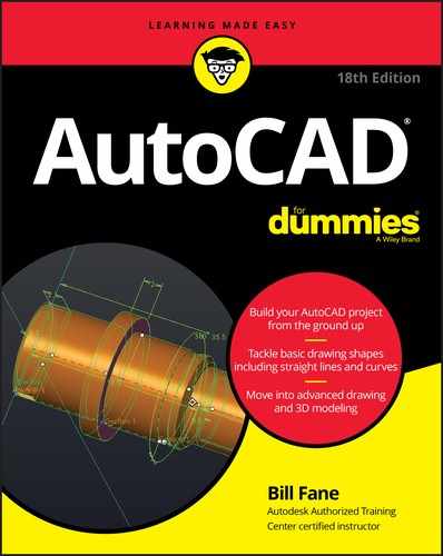
Click the New Viewports tab to make it current; then choose Four: Left (my preference) or Four: Right from the Standard Viewports list box.
The Preview panel shows a large, squarish viewport occupying most of the work area, with three small, squarish viewports stacked on the left (or right). The default 2D setup shows the visual style of all four viewports as 2D Wireframe. I explain visual styles in Chapter 21.
-
From the Setup drop-down list, choose 3D.
The visual styles remain as 2D Wireframe, but the view direction (listed as Current in 2D Setup) is now SE Isometric in the large viewport, and the three small viewports show Top, Front, and Right orthographic views.
 When modeling in 3D, look at objects in different ways at the same time. When looking at orthographic views (as in drafted drawings), you may want to see all your linework. But you can get a better sense of the three dimensionality of the model by looking at it in a shaded view. By using multiple viewports, you can do both at the same time.
 -
In the Preview area, click inside the large SE Isometric viewport and then choose Conceptual from the Visual Style drop-down list.
You’re almost finished. Rather than complete this setup every time you want to do some modeling, give the new viewport configuration a name.
-
In the New Name box at the top of the Viewports dialog box, enter a name such as V3D, for example, for the configuration.
Figure 22-2 shows the new, named viewport configuration.
-
Click OK to save the viewport configuration and close the Viewports dialog box.
In Figure 22-3, I turned off the grid in the three small orthographic viewports, but whether you leave it on or turn it off is a matter of personal preference.
 The Home button in the ViewCube can trip you up by changing to a view you don’t expect. I introduce the ViewCube in Chapter 21. If you want to keep the current SE Isometric viewpoint, be sure to reset the Home view. To do this, simply right-click anywhere in the ViewCube and choose Set Current View as Home from the menu that appears. And because you’ve gone to the trouble of setting up a shaded 3D viewport, you might want to make it a little more realistic and turn on perspective mode at the same time. Personal preference rules here, but architects tend to use perspective, and mechanical designers use parallel views.
 -
In the large 3D viewport, right-click the ViewCube to display its shortcut menu and then choose Perspective with Ortho Faces (see Figure 22-4).
Selecting Perspective shows the orthographic views in Perspective mode, and usually you don’t want that. Selecting Perspective with Ortho Faces resets the projection mode from Perspective to Parallel when you switch to an orthographic view.
-
Repeat Step 10, this time selecting Set Current View as Home.
Now you can readily return to this viewport configuration, keeping the same viewpoint in all viewports, perspective projection in the 3D viewport, and parallel projection in the orthographic viewports.
The last thing to do is save the configuration you just set up as a template (
.dwt) file. -
Click Save on the Quick Access toolbar. From the Files of Type drop-down menu, choose AutoCAD Drawing Template (
*.dwt) and enter a filename. Click Save.AutoCAD saves the new 3D template file in the same location as your other templates so that you can always select it when you want to do some serious 3D modeling.
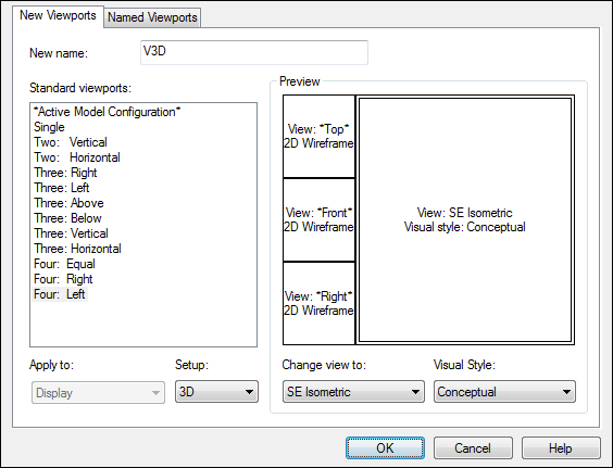
FIGURE 22-2: Setting up a 3D work environment in the Viewports dialog box.

FIGURE 22-3: It’s 2D and 3D all at the same time.
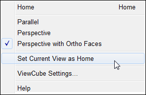
FIGURE 22-4: Changing settings in the right-click menu in the ViewCube.
To return to a single viewport later, simply click the plus (+) sign on the in-canvas viewport control.
Conversely, you can restore your four-viewport configuration at any time by clicking the Named Viewports tab, choosing V3D (or whatever name you used in Step 8), and clicking OK.
Seeing the world from new viewpoints
When you choose 3D in the Setup drop-down list in the Viewports dialog box, you direct AutoCAD to change the viewpoint in each viewport. The default viewpoints when you choose a four-viewport arrangement are top, front, right, and SE (southeast) isometric. These viewpoints work well for viewing and constructing simple models, but eventually you may want to specify your own, custom viewpoint in a particular viewport.
In both AutoCAD and AutoCAD LT, the best (but not the easiest) way to change viewpoints is to use the drop-down list in the Views panel of the View tab, as shown in Figure 22-5, to switch to a standard orthographic 3D view or an isometric view:
- The six standard orthographic (straight-on) views: Top, Bottom, Left, Right, Front, and Back.
- The four standard isometric views: SW (left-front), SE (right-front), NE (right-back), and NW (left-back). An isometric view is one in which you see the object from above, but not from too high above, as though you were hovering in a low-flying helicopter or receiving an image from a remote-operated drone, if they are still legal by the time you read this.
FIGURE 22-5: The preset views drop-down menu.
The easiest (but not the best) way to change viewpoints is to click a named face on the ViewCube (not available in AutoCAD LT). I don’t recommend this strategy because the ViewCube is only a viewing aid. You usually change to an orthographic view because you want to do some drawing or modeling there, and for that task, the user coordinate system (UCS) ought to orient itself with the view. See Chapter 21 for the skinny on UCSs. Clicking Front on the ViewCube shows you a nice front view of the model, but it leaves the UCS unchanged, and that can make drawing anything difficult. Clicking Front in the Views panel on the View tab does change the UCS to Front so that it matches the view and lets you draw without difficulty.
These ten views are standard because they’re often used in manual drafting and rendering work. They work well for showing 3D models of common objects such as mechanical components and buildings. You can also change to plan view, which is a top-down view of either the world coordinate system or a user coordinate system. I describe coordinate systems in Chapter 21.
The full version of AutoCAD has the ViewCube, the 3DOrbit command, and the Shift+middle mouse button methods of changing 3D viewpoints. All are described in Chapter 21. The options in AutoCAD LT are much more limited — you can set nonstandard viewpoints by typing ddVPoint and pressing Enter. In the Viewpoint Presets dialog box that appears, specify these settings:
- A viewing angle in the X,Y plane: Imagine moving a camera on a dolly around an object while keeping the camera at the same elevation.
- An angle from the X,Y plane: Imagine using a boom to swoop the camera to a different height so that you’re looking at the object from increasingly steep angles.
AutoCAD users can set viewpoints the same way, but it’s grossly inefficient compared with the other viewing options.
By default, AutoCAD shows 3D models in 2D Wireframe mode, even if you’ve created surface or solid objects. If you want to better visualize which objects are in front of which other objects, especially in an isometric or other non-orthogonal view, you have a couple of options:
- Select a shaded visual style such as Realistic, Conceptual, X-Ray, or Shades of Gray, from the Visual Styles drop-down list on the Visual Styles panel of the View tab. See Chapter 21 for the lowdown on visual styles.
- Render the model, as described in Chapter 23.
AutoCAD LT doesn’t include visual styles because they’re not much use in 2D drafting. A drawing saved in a visual style in the full version of AutoCAD does display that style when it’s opened in AutoCAD LT. However, you have no way to change it to 2D Wireframe (or anything else) so that you can work on it.
From Drawing to Modeling in 3D
This section introduces three techniques for creating 3D objects: drawing 3D lines and polylines, creating 3D objects from 2D geometry, and creating solids. In AutoCAD LT, you can use only the first two techniques. AutoCAD is also quite capable at surface modeling, offering both freeform mesh and NURBS surfaces. If you’re interested in either of these, check out the online Help system; in the Search field, enter creating meshes or surface models. Topics include creating surfaces and meshes from scratch and creating solids and surfaces from 2D objects.
 When you draw 3D objects (as when you draw 2D objects), place them on appropriate layers and use precision techniques to specify each point and distance. See Chapter 8 for more information about precision techniques.
Drawing basic 3D objects
The most basic forms of 3D geometry are wireframe-like objects created by picking points or entering X,Y,Z coordinates. These objects have no surfaces, so they look the same in 2D Wireframe mode or photorealistic renderings. They’re most useful as paths for sweeps and lofts, or as edges for surface creation. Basic 3D objects include the ones described in this list:
- Line: The line is a 2D object; although you can specify different Z coordinates for start points and endpoints so that they’re not coplanar with the world coordinate system, each individual segment is based on its own 2D plane. You can, however, use the line for constructing objects in 3D space.
- 3D Polyline: This object, created by using the 3DPOLY command, is similar to the 2D polyline that I describe in Chapter 6, except that the vertices of a 3D polyline can have different Z coordinates: a 2D polyline must be planar. Three-dimensional polylines are useful as paths for sweeps or for fly-throughs. I don’t cover walk-throughs or fly-throughs in this book.
- Spline: This free-form curve is created by using the SPLine command. I describe it in a 2D context in Chapter 7. Splines are 3D objects, and vertices can have different Z values. The spline is a better option than the 3D polyline for sweeps because it has smoother curves.
- Helix: A helix can be either 2D (think of a mosquito coil or the element on an electric range) or 3D (think of Mr. Slinky). It’s made by using the HELIX command and is especially useful as a path for threaded objects.
You can find the Line, 3DPOLY, and SPLine commands in the Draw panel on the Home tab of the Ribbon; the HELIX command is on that panel’s slideout.
The 3DPOLY command is similar to the PLine (plain old 2D polyline) command. Though both commands draw a series of connected line segments, they have different capabilities:
- The 3DPOLY command accepts 3D points for the line segments’ vertices. The PLine command requires that all vertices be on the same plane.
- 3DPOLY is limited to straight line segments. The PLine command can draw arc segments and create segments with a uniform or tapered width.
- Segments created using 3DPOLY can’t display dash-dot linetypes, so 3D polyline segments always display as continuous lines.
The command sequence for drawing 3D segments with the Line or 3DPOLY command is the same as for drawing 2D segments with the Line or PLine command; see Chapter 6 for information on drawing lines. The only difference is that you specify 3D coordinates instead of 2D ones. Figure 22-6 shows an example.
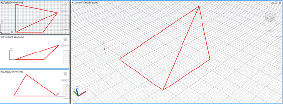
FIGURE 22-6: Entering 3D coordinates to draw a 3D polyline.
Creating 2D representations in this way is straightforward, although tedious, for all but the simplest objects. More important, a wireframe model becomes increasingly difficult to decipher as the complexity of the model increases. You see a mass of lines representing the edges, and you have difficulty telling which parts of which edges are in front of others. To reduce this visual confusion, you need to graduate to surface or solid modeling commands. I introduce you to solid modeling later in this chapter.
Gaining a solid foundation
Solid modeling is in many ways the culmination of 3D CAD. Solids more accurately represent most real-world objects than do wireframes or surfaces. And even when representational accuracy isn’t the main issue, it’s easier to construct many kinds of models with solids.
Many special-purpose solid modeling programs use a combination of solid and surface modeling techniques for maximum flexibility in constructing and editing 3D models. These kinds of programs — and solid modeling in general — are especially popular in mechanical design.
Constructing the basic building blocks, or solid primitives, for a solid model in AutoCAD isn’t difficult. Just follow these steps:
-
Define a suitable user coordinate system (UCS).
The UCS controls the construction plane and basic 3D orientation of the solid. Read about changing planes in Chapter 21.
-
Click the down arrow below the leftmost button in the Modeling panel on the Home tab, and then choose a solid primitive from the drop-down list.
As shown in Figure 22-7, your choices are Box, Cylinder, Cone, Sphere, Pyramid, Wedge, and Torus. The Ribbon remembers the last one used.
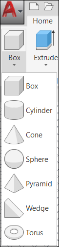
FIGURE 22-7: Everything you need for a solid foundation.
When you see a 3D object in a drawing, you can’t tell by looking whether it’s a 2D extruded object, surface mesh, or solid — to find out, open the Properties palette and select the object. The drop-down list at the top of the palette shows the type of object you selected.
Drawing solid primitives
Solids are the easiest kinds of object to work with if you’re new to 3D. The two types of 3D solid object are
- Primitive: The most basic of 3D building blocks, such as boxes, cones, and spheres. Primitive solids are based on simple geometric shapes, such as lines and circles.
- Complex (or compound): Made by combining primitive solids and (optionally) editing them with Boolean operations. The following sections focus on creating and modifying 3D solids.
Boolean editing operations (named for the Victorian English mathematician George Boole) use arithmetic-like functions to combine solid objects or remove parts of them. The three primary Boolean commands in AutoCAD are UNIon, SUbtract, and INtersect. See “Boolean operations,” later in this chapter, for more information.
Adding the Third Dimension to 2D Objects
The 2D roots of AutoCAD run deep. Drafting continues to be the primary focus of the program, but recent AutoCAD releases shifted focus to become increasingly more adept at 3D modeling. This section invites you to create new 3D objects from (what I presume is an abundance of) 2D objects.
You can create 3D objects from 2D objects by using a number of different techniques. You can add thickness or extrude an open 2D object to create a surface, or take multiple 2D cross sections and create a lofted object that adapts to the shape and size of each cross section that’s selected.
Everything mentioned in this main section applies only to AutoCAD (not to AutoCAD LT), with the exception of the thickness property.
Adding thickness to a 2D object
Most 2D objects, such as lines and circles, have a thickness property. Changing the thickness property of a 2D object doesn’t create a true 3D object, but it does create a pseudo-surface that looks like a 3D surface. These pseudo-surfaces can hide objects beyond them, but they have limitations. If you add thickness to a circle, an open cylinder is created without caps on the top and bottom. If you change the thickness of a rectangle (which is a polyline), you end up with four walls but no top or bottom.
Extruding open and closed objects
![]() Thickness is one way of adding height to an object, but extruding an object is usually a better approach. You can extrude open or closed 2D objects to create a 3D object. Extruding a closed 2D object (such as a closed polyline, spline, ellipse, circle, or region) creates a 3D solid. Extruding an open 2D object (such as an open polyline, spline, line, or arc) creates a 3D surface. Figure 22-8 shows the result of extruding open and closed objects.
Thickness is one way of adding height to an object, but extruding an object is usually a better approach. You can extrude open or closed 2D objects to create a 3D object. Extruding a closed 2D object (such as a closed polyline, spline, ellipse, circle, or region) creates a 3D solid. Extruding an open 2D object (such as an open polyline, spline, line, or arc) creates a 3D surface. Figure 22-8 shows the result of extruding open and closed objects.
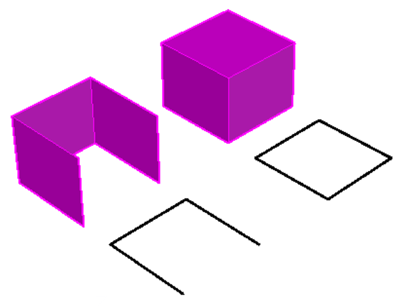
FIGURE 22-8: Converting 2D to 3D by extrusion is as easy as 1-2-3.
If you want to end up with a 3D solid, you must extrude a single, closed object, such as a circle or a closed polyline. If you want to produce a 3D solid from a boundary composed of multiple objects, read about PRESSPULL in the later section “Pressing and pulling closed boundaries.”
To extrude an open or a closed 2D object, click Extrude in the Solid panel on the Solid tab, or click the Extrude split button in the Modeling panel on the Home tab. If you see a button labeled Loft, Revolve, or Sweep, click the lower part of the split button and choose Extrude from the drop-down menu. Use the MOde option to control whether you create a surface or 3D solid from a closed object, select the objects you want to extrude, and specify an extrusion height or distance to create the 3D solid.
The DELOBJ system variable controls whether the 2D objects you use to create 3D solids are retained or erased. Most of the time, you’ll want to keep the source geometry, but the default DELOBJ setting erases it. If you want to keep the original 2D geometry, type DELOBJ and set its value to 0. See Chapter 23 for more about system variables. DELOBJ also controls whether the source objects for associative arrays (introduced in Chapter 18) are retained or deleted.
Pressing and pulling closed boundaries
![]() The PRESSPULL command allows you to create 3D geometry by extruding a closed boundary. PRESSPULL differs from EXTrude in that the EXTrude command requires a single, closed 2D object, whereas PRESSPULL can use closed boundaries formed by other 3D solids, or by several objects that form a closed region. PRESSPULL searches for a suitable boundary in exactly the same manner as the Hatch command, which I cover in Chapter 15.
The PRESSPULL command allows you to create 3D geometry by extruding a closed boundary. PRESSPULL differs from EXTrude in that the EXTrude command requires a single, closed 2D object, whereas PRESSPULL can use closed boundaries formed by other 3D solids, or by several objects that form a closed region. PRESSPULL searches for a suitable boundary in exactly the same manner as the Hatch command, which I cover in Chapter 15.
To press or pull within a closed boundary to create a 3D object, click Presspull in the Solid panel on the Solid tab, click inside an enclosed boundary, and then drag or specify the distance on the extrusion you want to create.
Lofting open and closed objects
 Lofting lets you select a series of 2D cross sections to create surfaces or 3D solids of varying cross sections, such as aircraft wings. The selected cross sections define the outer surface that’s generated. You must select a minimum of two cross sections. If you select open objects, the resulting loft is a 3D surface; if you select closed objects, the resulting loft can be either a surface or 3D solid, depending on the current value of the MOde option for the LOFT command.
You can loft objects along a path by using guide curves, or only between selected cross sections, as shown in Figure 22-9. To loft open or closed 2D objects, open the Sweep/Loft drop-down menu in the Solid panel on the Solid tab. Use the MOde option to control whether you create a surface or 3D solid from a closed object cross section, and specify how the loft object should be calculated.
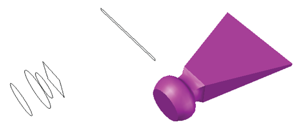
FIGURE 22-9: Using cross sections to create a lofted object.
Sweeping open and closed objects along a path
 Sweeping is similar to extruding a 2D object except that you specify a path rather than a height or distance. The object used as the path can be either an open or a closed 2D object and can be only a single object, as shown in Figure 22-10. If you sweep an open object, the resulting swept object is a 3D surface; if you sweep a closed object, the resulting swept object is a 3D surface or 3D solid based on the current value of the MOde option of the SWEEP command. To sweep an open or a closed 2D object, open the Sweep/Loft drop-down menu in the Solid panel on the Solid tab. Use the MOde option to control whether you create a surface or 3D solid from a closed object, select the objects to sweep, and specify a path for the sweep.
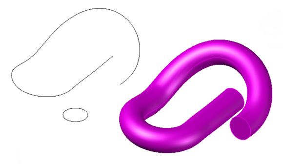
FIGURE 22-10: Sweeping a closed object along a path.
Revolving open or closed objects around an axis
![]() Revolving lets you create a 3D surface or 3D solid by turning selected objects around an axis, as shown in Figure 22-11. If open objects are selected, the resulting revolved object is a 3D surface; if you select closed objects, the resulting revolved object is a 3D solid.
Revolving lets you create a 3D surface or 3D solid by turning selected objects around an axis, as shown in Figure 22-11. If open objects are selected, the resulting revolved object is a 3D surface; if you select closed objects, the resulting revolved object is a 3D solid.
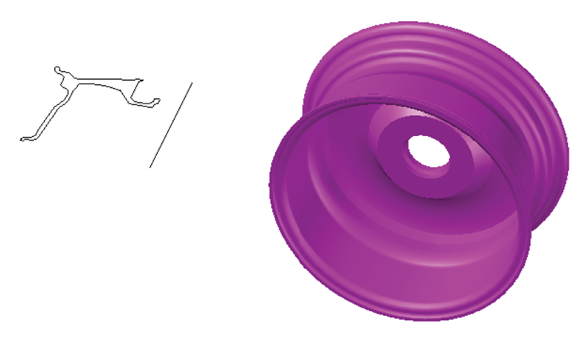
FIGURE 22-11: Revolving a closed object around an axis.
To REVolve an open or a closed 2D object, click Revolve in the Solid panel on the Solid tab, or click the Revolve split button in the Modeling panel on the Home tab. If you see a button labeled Loft, Extrude, or Sweep, click the lower part of the split button and choose Revolve from the drop-down list. Use the MOde option to control whether you create a 3D surface or 3D solid from a closed object, select the objects to revolve, and specify the axis to use.
Modifying 3D Objects
Many modification techniques and commands that you use in 2D drafting can be applied to 3D modeling. In addition, a specialized set of 3D editing commands is available. All these commands are in the Modify panel on the Home tab when the 3D Modeling workspace is current.
Selecting subobjects
Three-dimensional objects themselves are complex objects that can be made up of several hundred, or perhaps even thousands, of objects. Although these objects never stray from their parents, you can access them individually or in groups via subobject selection: selecting a vertex, an edge, or a face of a 3D object. After you select a subobject, you can use grip editing and the 3D gizmos (discussed in the later section “Working with gizmos”) to manipulate it.
To more easily select subobjects, you can enable subobject filtering from the Ribbon. Vertex, edge, and face filters are located on the Subobject Selection Filter split button in the Selection panel on the Home and Solid tabs.
The CULLINGOBJ and CULLINGOBJSELECTION system variables help limit object selection to the faces that are visible in the current view by ignoring faces around the back of the objects being viewed. By default, both these variables are turned off, so you can select objects in front and behind. If you have a complex model, turn on culling by clicking Culling in the Selection panel on the Home tab. To turn off culling, click the Culling button again. The button is shaded blue when the feature is enabled.
If you need to select only a face on a 3D object, press and hold the Ctrl key and select the face you want to select. This method can be faster than turning subobject filters on and off.
Working with gizmos
Although you can use the Move, ROtate, and SCale commands to modify 3D objects, they can sometimes give unexpected results in 3D. Enter the 3DMOVE, 3DROTATE, and 3DSCALE commands, which all use a gizmo or grip tool when a non-orthographic view is current (see Figure 22-12).
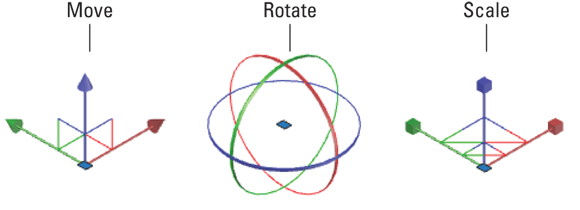
FIGURE 22-12: Using gizmos to modify objects in 3D.
A gizmo restricts or constrains movement along the X,Y plane and the Z-axis. To use a gizmo, click an axis on the tool to restrict movement to that axis. You can access the three gizmos by using these methods:
- 3DMOVE: Click 3D Move in the Modify panel on the Home tab, or type 3DMOVE at the command line.
- 3DROTATE: Click 3D Rotate in the Modify panel on the Home tab, or type 3DROTATE at the command line.
- 3DSCALE: Click 3D Scale in the Modify panel, or type 3DSCALE at the command line.
You can also access the Move, Rotate, and Scale gizmos in 3D by selecting objects when no command is active. You can set the default gizmo that is displayed when you use grips in 3D by opening the Gizmo drop-down menu in the Selection panel on the Home tab and selecting the gizmo that you want to be active. Right-clicking a gizmo lets you switch between different gizmos and constraints.
More 3D variants of 2D commands
Moving, rotating, and scaling objects are certainly the Big Three operations of 3D editing, but a number of other 3D variations on 2D editing commands are hiding in the wings, awaiting their turns in the spotlight. For more about spotlights, see Chapter 23.
Getting your 3D ducks in a row
Making objects align with each other in 3D can be a challenge at times, especially if you need to not only move an object in 3D but also rotate and scale it based on the specified alignment. AutoCAD has two commands you can use to align objects:
- ALign: Used to align 2D and 3D objects based on one, two, or three pairs of points. Based on the number of pairs of points that are specified and how they’re selected, the ALign command might move and rotate the selected objects into place. It can also be used to scale objects. On the Home tab, choose Align from the Modify panel slideout.
- 3DALign: An improved version of the ALign command that includes additional options as well as the ability to move and rotate a copy of the selected objects and use Dynamic UCS with the command. Click 3D Align in the Modify panel on the Home tab.
Holding up a mirror
The MIrror command is limited to working on the X,Y plane. If you want to mirror objects in 3D, you use the MIRROR3D command. Click 3D Mirror in the Modify panel on the Home tab. The MIRROR3D command is similar to the MIrror command, but you can control the plane on which the mirroring is performed.
The generic 2D MIrror command works also in 3D, but you must employ a trick. As indicated in the preceding paragraph, MIrror works only in the X,Y plane — but it doesn’t have to be the World X,Y plane. The command works equally well in the X,Y plane of the current user coordinate system (UCS).
Associative arrays, which I discuss in Chapter 18, work in 3D as well as in 2D. AutoCAD has long had the 3DARRAY command; it’s similar to the old-style ARray command (refer to Chapter 11 to read about that one) in that it doesn’t create an associative array object. For information on creating rectangular, polar, and path array objects, refer to the online Help system.
Editing solids
You can edit 3D solids in a variety of different ways that you can’t edit other objects. You can use grip editing to change the shape of 3D solids, or use Boolean operations on a 3D solid to create complex models. You can fillet and chamfer the edges of a 3D solid by using the FILLETEDGE and CHAMFEREDGE commands.
Using grips to edit solids
Grip-editing is one of the most direct ways to modify an object. To edit a 3D solid by using grips, select the 3D solid when no command is running, and then select the grip that you want to use to edit the solid. Pay close attention to the grip you select; some grips give you control over changing the overall size of a solid; others might change only part of a solid, such as the face or top radius of a cone. Figure 22-13 shows a pyramid with its top radius being edited with grips.
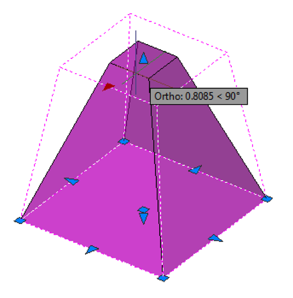
FIGURE 22-13: Grip-editing a pyramid.
Boolean operations
![]()
![]()
![]() As I mention in the earlier “Drawing solid primitives” section, you can join 3D solids by using the UNIon command to create a new 3D solid. You can also subtract volume from a 3D solid by using another, intersecting 3D solid to determine what should be removed with the SUbtract command. The INtersect command can be used to calculate a new 3D solid based on the volume that is common to two or more intersecting 3D solids. See Figure 22-14 for examples. You can find these three commands in the Boolean panel on the Solid tab.
As I mention in the earlier “Drawing solid primitives” section, you can join 3D solids by using the UNIon command to create a new 3D solid. You can also subtract volume from a 3D solid by using another, intersecting 3D solid to determine what should be removed with the SUbtract command. The INtersect command can be used to calculate a new 3D solid based on the volume that is common to two or more intersecting 3D solids. See Figure 22-14 for examples. You can find these three commands in the Boolean panel on the Solid tab.
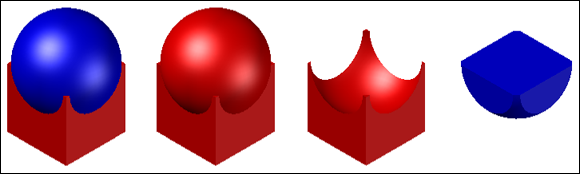
FIGURE 22-14: Solid primitives on the left, and the result of using the UNIon, SUbtract, and INtersect commands.
Boolean operations are probably the most-used of the 3D commands. Yes, primitive solids such as a box or a wedge are easy to use, but most real-world 3D objects are more complex than the simple primitives. Something as apparently simple as a connecting rod on a car engine might require a dozen or so Boolean operations to add and subtract simpler solids until you arrive at the final design.
![]() You will often need to change to a different user coordinate system (UCS) before placing the next subobject to be combined with the base object. The easiest way to do this is to turn on UCSDETECT (F6) on the status bar. Then, as you move the cursor around while a create command is active, AutoCAD will automatically snap the UCS to any planar surface that it passes over.
You will often need to change to a different user coordinate system (UCS) before placing the next subobject to be combined with the base object. The easiest way to do this is to turn on UCSDETECT (F6) on the status bar. Then, as you move the cursor around while a create command is active, AutoCAD will automatically snap the UCS to any planar surface that it passes over.
Filleting and chamfering
Because fillets and chamfers are common real-world features, it’s logical that tools for creating them are available. You can fillet or bevel the edges of a 3D solid by clicking the Fillet Edge (or Chamfer Edge) split button in the Solid Editing panel on the Solid tab.
Both commands allow you to select multiple edges to fillet or bevel. When you select an edge, AutoCAD gives you feedback on how the selected edge will be affected. Figure 22-15 shows an L-shaped 3D solid that has been filleted and chamfered.

FIGURE 22-15: Before and after filleting and chamfering a 3D solid.
To remove a fillet or chamfer, start the Erase command. Then, at the Select Objects prompt, hold down the Ctrl key and select the fillet or chamfer to be removed. For fillets, you may need to also remove nearby filleted corners that might have been created during the application of the fillet.
The FILLETEDGE and CHAMFEREDGE commands were new in AutoCAD 2011. You can still use the Fillet and CHAmfer commands on 3D solids, but the new commands are much more efficient.
Slice
The SLice command lets you cut a 3D solid along a plane. You can slice a 3D solid by using a planar curve, such as a circle, 2D polyline, or surface, among many others. When you slice a 3D solid, you can choose which part of the 3D solid is retained, or you can keep both. Figure 22-16 shows a solid model that has been sliced in half.
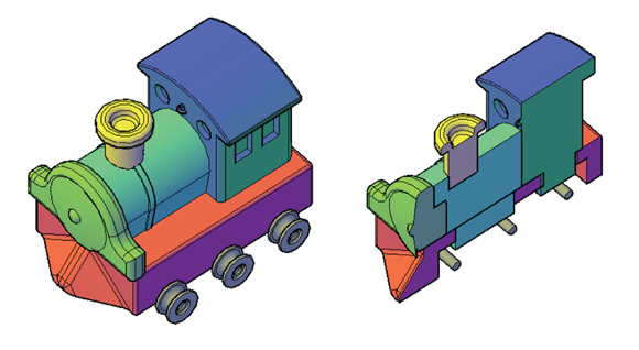
FIGURE 22-16: Carving up a solid model with the SLice command.
To start the SLice command, choose Slice from the Solid Editing panel on the Solid tab. After the command is started, specify a 3D solid to slice, an axis or object to define the cutting plane, and then, finally, which new 3D solids to keep.