Chapter 15
Down the Hatch!
IN THIS CHAPTER
![]() Adding hatch patterns to drawings
Adding hatch patterns to drawings
![]() Applying annotative hatch patterns
Applying annotative hatch patterns
![]() Choosing hatch boundaries
Choosing hatch boundaries
![]() Using predefined and user-defined hatch patterns
Using predefined and user-defined hatch patterns
![]() Editing hatches
Editing hatches
If you need to fill in closed areas of drawings with special patterns of lines (crosshatches, or simply hatches) or solid fills, then this is your chapter. If you were hoping to hatch a plot or plot a hatch, see Chapter 16. If you want to hatch an egg, look at Raising Chickens For Dummies, by Kimberly Willis and Robert T. Ludlow (Wiley).
A hatch in AutoCAD is a separate object that fills a space; has an appearance dictated by the hatch pattern assigned to it; and is associated by default with the objects that bound the space, such as lines, polylines, and arcs. If you move or stretch the boundaries, AutoCAD normally updates the hatches to fill the resized area.
Creating a Hatch
Drafters often use hatches to represent the type of material that makes up an object, such as insulation, metal, or concrete. In other cases, hatches helps emphasize or clarify the extent of a particular element in the drawing — for example, showing the location of walls in a building plan or highlighting a swampy area on a map so that you know where to avoid building the road. Figure 15-1 shows an example of hatches in a structural detail. In mechanical design, it’s used to show the cut faces of cross sections.
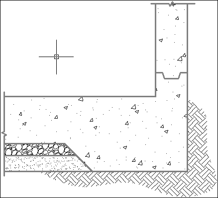
FIGURE 15-1: A big batch o’ hatch.
This section gives you a jump-start on the basic process used to create hatches and shows you how easy the process is. I also cover many of the options included on the Hatch Creation contextual tab on the Ribbon, shown in Figure 15-2, and how to edit existing hatched areas.
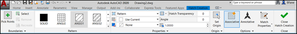
FIGURE 15-2: The Hatch Creation contextual tab on the Ribbon.
Follow these steps to hatch an enclosed area by using the pick points method of selecting the hatch area:
-
Start a new drawing, using the
acad.dwttemplate for Imperial units oracadISO.dwtfor metric units.Draw a circle with a radius of 5 units (Imperial) or 50 units (metric). Draw a second circle inside the first with a radius of 2 units (Imperial) or 20 units (metric).
-
 Start the Hatch command by typing H and pressing Enter or by clicking the Hatch button in the Draw panel of the Home tab on the Ribbon.
The Hatch Creation contextual tab on the Ribbon appears, as shown in Figure 15-2. Ignore it for now.
-
Move the cursor on the screen.
As the cursor moves within any enclosed area in the drawing, a preview appears to show you how the final hatches will look if you pick a point inside that particular area. Starting from outside the larger circle, move it into the space between circles, and then into the inner circle, and then back into the space between circles and note the changes.
-
Change some hatch options.
The quick preview updates as you select variants or change values in the Hatch Ribbon panel. Try different patterns. The three little arrows along the right side of the Pattern panel scroll through all the different patterns that are available. My favorite is Escher.
-
Pick a point in the region between the circles and then press Enter or the spacebar.
Congratulations — in only a few seconds, you’ve done something that would have taken an hour or more in the days of pencil and paper.
- Change the diameter of the outer circle:
- Click the outer circle and then click and drag one of the four outer grips to change the diameter of the circle. The hatch pattern updates to match. This process is known as associative hatching.
- Click the inner circle, and then click and drag its center grip to move it outside the larger circle. The hole in the pattern of the larger circle fills in and the smaller circle gets filled with hatching.
- Click the smaller circle and then click and drag its center grip to move it back inside the larger circle. The smaller circle loses its hatch and reverts to cutting a hole in the hatch of the larger circle.
When working with hatches, keep these tips in mind:
- Place the hatches on a dedicated layer or layers. You can then easily turn hatches on or off.
- Always use the Continuous line type for hatch layers. Most hatch patterns use noncontinuous lines that are generated as patterns by the hatch process. If you place hatches on a layer with a noncontinuous line type then the Hatch command tries to create each of its own noncontinuous line segments from noncontinuous lines and the hatch process gets a little bizarre.
- Modify each hatch separately. By default, when you select a number of separate, closed areas and then press Enter, the hatched areas are created as a single object. Later, if you edit one hatched area then all areas in the original set update. A good example of this would be the cross-section of a complex mechanical part. Choose Create Separate Hatches on the Options slideout panel if you want to be able to modify each hatched area.
- Set the Draw Order drop-down list to specify whether the hatch objects are in front of or behind the hatch boundary or other drawing objects, as shown in Figure 15-3. By default, they’re sent behind their boundary, which is typically what you want. If a hatch is a different color from its boundary and if it’s in front of its boundary, the tips of the hatch objects produce a dotted-line effect along the boundary.
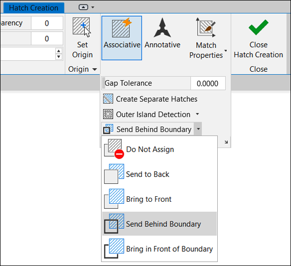
FIGURE 15-3: Hatch options for every occasion.
Starting with AutoCAD 2017, you can set up AutoCAD so that hatches are automatically placed on the correct layer. Follow these steps:
-
 Start the LAyer command.
To do so, click the Layer Properties button on the Layers panel of the Home tab.
-
Create a new layer.
Give it a suitable name, such as Hatch, and assign it a color. I discuss layers in Chapter 9.
-
Start the Hatch command.
Type H and press Enter or click the Hatch button on the Draw panel of the Home tab.
-
Select your Hatch layer.
Click the down arrow at the bottom of the Properties tab to see the slideout panel and select your Hatch layer from the drop-down list.
-
Close the Hatch Creation tab by clicking the Close button.
That’s it! From now on, whenever you create a hatch pattern in this drawing it will automatically land on the Hatch layer, regardless of which layer is currently active.
 Create and set your default Hatch layer in your template drawing. Then any new drawings you create from your template will automatically have the Hatch layer predefined. I discuss templates in Chapter 4.
Using the Hatches Tab
Now that you know how easily you can create hatched areas, you can explore the main options within the contextual Hatch tabs of the Ribbon. When you start the Hatch command, you see the Hatch Creation tab. (Refer to Figure 15-2.) But if you double-click an existing hatch, you see the Hatch Edit tab, and they’re virtually identical.
Working from left to right, the Hatch tab contains these options:
-
Boundaries: The easiest, most intuitive, and most common way to define the boundary of a hatch is to simply pick inside a region. If you pick multiple regions within one run of the Hatch command, each region is hatched, and the result is one hatch object. If you edit the properties of any region later, all regions are updated. This strategy is commonly used when hatching the cut faces of a cross section; all faces common to a single item automatically maintain matching hatch properties.
Choose Create Separate Hatches on the Options slideout panel if you want to be able to modify each hatched area independently.
You can also select an area to be hatched by picking specific objects to define the boundary, but you must select enough objects to define a fully enclosed region. In the earlier section “Creating a Hatch,” you can see how the hatch pattern behaves when you select the region between the circles; it doesn’t hatch the inner circle. This is island detection. If you select specific objects for the boundary, island detection is turned off. If you had selected only the outer circle, the hatches would run right over the inner circle.
Starting with AutoCAD 2014, if you’re picking within multiple bounded areas or selecting individual objects, the Hatch command includes an Undo option in case you accidentally pick the wrong area or object.
 No matter which selection method you choose, the boundary must be airtight. Boundary objects can overlap, but they can’t have leaks — not even microscopic ones. Technically, a fuzz factor can be set to allow for tiny leaks. However, I don't tell you how to set a fuzz factor because it defeats the purpose of drawing with precision. Whenever you see the error message
 A Closed Boundary Could Not Be Determined, you need to repair lines or other objects so that they define a fully airtight boundary. Sometimes, you can use the Fillet command with a 0 (zero) fillet radius to force two lines to meet exactly. Another possibility is to use grip editing to align one endpoint precisely with another (see Chapter 11). The Hatch command displays red circles at gaps in the not-quite-enclosed area you want to hatch. Even if it doesn’t fix the gaps, it shows you where you should fix them. -
Pattern: The scroll arrows at the right edge of the Pattern panel give access to the 82 predefined hatch patterns, including nine solid and gradient fills that ship with AutoCAD.
 Hatch patterns are defined by external files named
 acad.patoracadlt.patin Imperial units, oracadiso.patoracadltiso.patin metric. Each file includes definitions for all patterns. You can create your own hatch patterns; the Customization Guide in the online Help system explains how. You can buy libraries of custom hatch patterns. Any patterns not defined inacad.patoracadiso.patare referred to as custom patterns, but you must be careful when using them. Because they’re external files, they must be available to AutoCAD whenever you open a drawing containing them. If you send the drawing to someone else, you must also send the pattern definition file, which can have copyright issues if you bought the patterns. Autodesk created the hatch patterns whose names begin with the characters AR- (that’s a hyphen at the end) particularly for use in architectural drawings, and unlike non-AR patterns, they do represent real objects such as brick and roof shakes. The AR patterns were designed with a final hatch scale of 1.0 in mind, but in some cases you have to adjust up or down to achieve a suitable scale.
 - Properties: The Properties panel contains buttons for as many as ten properties that can be attached to hatches, but many of them can be covered in other ways. I identify them by their default values — your results may differ:
- Pattern: See the Pattern panel.
- Use Current: This button, which refers to color, should nearly always be ByLayer, which is what the current general color override should be.
- None: This button refers to background color, which can be useful when using hatching to portray actual objects. For example, a brick pattern can have a red background so that the hatched region looks like red bricks, as shown in Figure 15-4.
- Hatch Transparency: The options for this button range from 0 percent (opaque) to 90 percent (nearly transparent).
- Angle: Hatch patterns can be rotated the way you want. For example, in mechanical design, you may be cutting a cross section of an assembly. Standard practice is to hatch the resultant cut faces, usually with ANSI31, and to adjust the rotation angles so that each part has a different angle to help distinguish one from another. Note that some patterns (the ANSI series, in particular) usually have an initial 45-degree rotation built in.
- Scale: Ah, here’s the big one (pun intended). I cover it in more detail in the “Scaling Hatches” section a little later in this chapter.
- Origin: AutoCAD typically creates hatched areas by having them radiate outward from the origin, effectively turning them on and off as they encounter boundaries. This behavior can cause problems with some real-object patterns, however. You wouldn’t want a brick wall to start with 68.3 percent of a brick, so the Origin option lets you snap to an exact point, as shown in Figure 15-4. You may also want to check out Chapter 9’s reference to the need for a brick layer.
- Options: This one has three suboptions:
- Associative: By default, hatches are associative to their boundaries. They know about each other, which explains what happens when you change and move boundary objects at any time after the hatching was created.
- Annotative: Like text (described in Chapter 13) and dimensions (described in Chapter 14), hatches must be scaled properly to match the drawing scale. I cover this topic in more detail in the later section “Scaling Hatches.”
- Match properties: This function lets you select an existing hatch object and then copy its properties onto another hatch object, just like the Format Painter in many Windows applications.
- Close: Surprise! This option closes the Hatch tab.
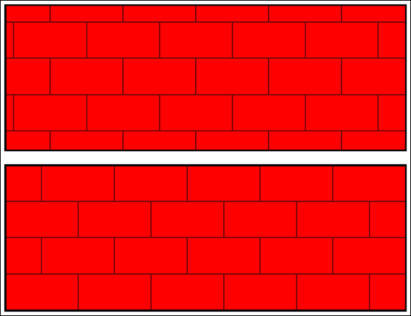
FIGURE 15-4: Poorly laid red bricks (top); properly laid red bricks (bottom).
Scaling Hatches
Hatches are annotation objects — like text (see Chapter 13) and dimensions (see Chapter 14) — in that they don’t directly contribute to the geometry of what you’re drawing. However, they do impart additional information.
Like text and dimensions, hatches also need to be scaled to suit the final drawing scale. Start with the common ANSI31 pattern. As defined, it produces parallel lines spaced 1/8" apart. So far, so good — but what if you’re drawing the cross section of a large part, such as the 10' boom on a backhoe? Remember to always draw at full size and then scale when you plot. If you were to apply hatches at the nominal 1:1 scale and then plot at 1:10 to fit the boom on a smaller sheet of paper, the 1/8" hatch spacing becomes 0.0125 inch, which effectively becomes a solid fill. As with text and dimensions, you apply a scale factor of 10 to the hatches. The hatch lines in the drawing file then turn out to be 1.25 inches apart, which scale down to 1/8" when you plot. I also discuss scale factors in Chapter 4.
Scaling the easy way
The easy way to scale a hatch is to select the drawing scale from the Scale List button in the lower-right corner of the AutoCAD screen, the same as you do for text (see Chapter 13) and dimensions (see Chapter 14), and then to turn on the Annotative option in the Options panel of the Hatch tab on the Ribbon. Now whenever you create hatches, they scale themselves correctly to suit the current plot scale.
The setting of the Annotative button is good for only the current editing session, and it must be reset if you add more hatches later. The AutoCAD Help facility states that this setting is saved in the drawing, but it isn’t.
![]() In Chapter 14 (which describes dimensions), I strongly recommend turning off the Automatically Add Scales option when placing annotative text and dimensions, because you normally don’t want everything to show at every scale, especially when creating details at other scales. Hatches, on the other hand, normally do show in every view at every scale, scaled accordingly. You might be tempted to turn this option back on for hatches, but if you do, the first time you change the drawing scale, the new scale is added to all existing annotative objects. The best practice is to edit the hatches and manually add scales, the same as I discuss in Chapter 13 for text and Chapter 14 for dimensions.
In Chapter 14 (which describes dimensions), I strongly recommend turning off the Automatically Add Scales option when placing annotative text and dimensions, because you normally don’t want everything to show at every scale, especially when creating details at other scales. Hatches, on the other hand, normally do show in every view at every scale, scaled accordingly. You might be tempted to turn this option back on for hatches, but if you do, the first time you change the drawing scale, the new scale is added to all existing annotative objects. The best practice is to edit the hatches and manually add scales, the same as I discuss in Chapter 13 for text and Chapter 14 for dimensions.
Don’t confuse annotative and associative, even though both are polysyllabic words that start with a and sit next to one another in the Options panel on the Hatch Creation tab. Annotative hatch objects scale themselves automatically to suit the drawing scale. Associative hatch objects (enabled by default) update to the new area when you change the hatch boundary. And if that isn’t enough, Chapter 19 covers parametrics, which include annotational annotative associative dimensions.
Annotative versus non-annotative
Figure 15-5 shows two versions of the same drawing, dressed up with annotative and non-annotative hatch patterns. As shown by the annotation scales displayed on the drawings’ status bars, the annotative hatches change their scales, whereas the non-annotative hatches remain unchanged.
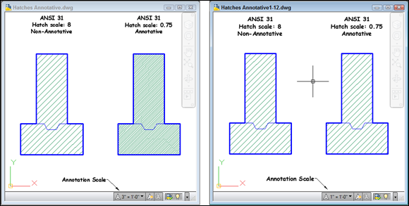
FIGURE 15-5: Hatches annotative (and not).
Chapter 14 shows another example: The hatches in both views are the same object, but because the viewports have different scales, the hatches adjust accordingly.
Before annotative hatches first appeared in AutoCAD 2008, the only way to create the effect in these two views in both drawings was to create two separate layers, one for each hatch scale, hatch the object twice, and then freeze and thaw layers as appropriate.
Pushing the Boundaries of Hatch
In the remainder of this chapter, you discover how to refine hatch techniques. I describe how to copy existing hatches, take advantage of various options in the Hatch and Gradient dialog box (which offers a bit more control than the Hatch Creation contextual tab), and choose more complicated hatch boundaries.
Adding style
A minor problem is that, unlike using text and dimensioning, you can’t create named styles for hatches. The good news is that three workarounds can help offset this issue.
Plagiarism 101 — editing hatches: Suppose that a drawing has several different styles of hatches applied with incorrect specifications. Simply select the problem hatch, click the Inherit Properties button on the Hatch Editor tab, and select an existing hatch to copy its properties. The original hatch inherits all properties of the selected hatch.
Select more than one problem hatch at a time to change multiple hatches at once.
Plagiarism 201 — cloning hatches: Suppose that a drawing has several different styles of hatches applied, and now you want to hatch another area. You start the Hatch command, and the Hatch contextual Ribbon appears. Oops — it shows the specifications of the last hatch that was applied, which is quite different from what you want to do now. Click the Match Properties button in the Options panel of the Hatch Creation tab, or click the Inherit Properties button in the Hatch and Gradient dialog box. Pick an existing hatch, and — presto! — all settings are updated to match the selected hatch. You can use the cloned settings as is, or you can modify them.
Plagiarism 301 — creating hatches: Here’s a technique that even many experienced users miss. It’s remarkably easy to customize AutoCAD so that a single mouse click can produce any hatch style you want. Here’s how:
-
Apply a hatch with the properties you want.
Make sure that the existing hatch is on the correct layer and that the layer has all the correct properties. -
Display the Tool Palette window.
Select the Tool Palettes tool in the Palettes panel on the View tab of the Ribbon. (I discuss tool palettes in Chapter 2.)
-
Display the Hatches and Fills palette by clicking its tab.
If you can’t see this tab, click the overlapping edges of the tabs at the bottom of the palette window and select Hatches and Fills from the list that appears.
-
Create a new Hatch tool.
Click once to select the existing hatch object, pause, and then select it again. Drag it to the tool palette and drop it.
Don’t double-click too quickly, and don’t click the blue grip, or else you’ll edit only the existing object. -
Use the new Hatch tool.
Click the Hatch tool, and then click inside a closed boundary in the drawing. Bingo — instant hatches to your specification. Note that the tool even puts hatches on the same layer as the original sample.
You can also simply click and drag the desired pattern from the tool palette to the desired boundary.
If you start a new drawing, create a boundary, and then use the Tool Palette to hatch it, you may be amazed to find that the new hatches in the new drawing are on the correct layer. If the correct layer doesn’t exist in the new drawing, AutoCAD creates it to match the original specifications automatically — a process known as standardization through customization.
Hatches from scratch
You can use predefined, user-defined, or custom hatch patterns. Most of the time, you’ll choose predefined hatch patterns unless some generous soul gives you a custom pattern. On the other hand, I haven’t used a user-defined pattern in over 25 years of using AutoCAD because hatches consist solely of continuous lines. All you can define are the spacing and rotation angle and whether the lines are parallel pairs. And all this can be duplicated with standard patterns.
An alternative to using the Ribbon to create the pattern is the Hatch and Gradient dialog box, as shown in Figure 15-6. You don’t see the hatch object updating as you change settings (as on the Ribbon), but you have more control over what you end up with. To display the Hatch and Gradient dialog box, click the dialog box launcher (the tiny arrow at the right end of the Options panel on the Hatch Creation tab of the Ribbon).
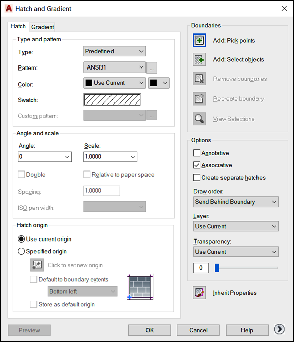
FIGURE 15-6: The Hatch tab in the expanded Hatch and Gradient dialog box.
By default, the right third of the Hatch and Gradient dialog box is hidden; to see additional hatch options at the right side of the dialog box (as shown in Figure 15-6), click the More Options arrow beside the Help button.
Pick a pattern — any pattern: Predefined hatch patterns
To use predefined hatch patterns in AutoCAD, select Predefined from the Type drop-down list at the top of the Hatch tab in the Hatch and Gradient dialog box. This selection sets the stage for choosing the hatch pattern.
You specify a predefined hatch pattern in one of two ways:
- Pattern drop-down list: If you know the name of the hatch pattern, select it from the Pattern drop-down list. The list is alphabetical, except that SOLID (that is, a solid fill) appears at the beginning.
- Pattern button: If you don’t know the pattern name or if you prefer the visual approach, click the Pattern button to display the Hatch Pattern palette with pattern previews and names. The Pattern button is the tiny button with the ellipsis (three dots) to the right of the Pattern drop-down list and pattern name.
Figure 15-7 shows more predefined hatch patterns, which cover everything from earth to Escher to stars.
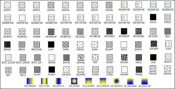
FIGURE 15-7: A veritable plethora of hatch patterns.
When is a pattern not a pattern? When it’s a solid fill
AutoCAD treats filling an area with a solid color as a type of hatch. Simply choose SOLID from the top of the Pattern drop-down list. You also see several gradient-fill options, where one color gradually changes to another.
Like any other object, a solid hatch takes on the current layer’s color if you leave (as you should) the color set to ByLayer, or it takes on the current object color override if someone else who doesn’t know what they’re doing has altered the drawing. Therefore, check whether the current object layer and color are set appropriately before you use the Solid hatches option. (See Chapter 9 for details.)
Here’s looking through you, kid
The transparency object property in AutoCAD is probably most useful (in 2D, anyway) when applied to solid fills. You can use transparent solid fills to demarcate (distinguish) areas on architectural floor plans or aerial photographs of project sites. In addition to ByLater and Solid settings, make sure that the current object or layer transparency is set correctly, too.
Editing Hatch Objects
Editing an existing hatch pattern is simple after you’re familiar with the Hatch Creation tab on the Ribbon. Follow these steps:
-
Select the hatch object.
AutoCAD opens the Hatch Editor contextual tab on the Ribbon and displays the hatch object’s current settings.
- Make any changes you want and watch the real-time preview as you do. When you’re happy, click Close Hatch Editor to retain the changes.
Alternatively, you can use the Properties palette or the Quick Properties palette (described in Chapter 9) to make most existing hatch pattern changes. By default, AutoCAD displays the Hatch Editor tab when you click a hatch object, and it opens the Quick Properties palette when you double-click a hatch object. The Quick Properties palette is especially useful for changing several hatches at a time.
Simple grip-editing is also available. Select a hatch and then hover the cursor over the round, blue center grip. A contextual menu opens to give you quick access to changing the hatch origin, angle, and scale. Don’t be misled by the Stretch option on the context menu, though: You can only move a hatch with this option, and when you do, it loses its associativity to its boundary.
Here are a few other hatch tips:
- To make one hatch look like another (without even opening the Hatch Editor tab): Click the Match Properties button in the Clipboard panel on the Home tab of the Ribbon.
- To mirror drawing geometry that includes hatches without mirroring the hatch angle: Use the MIRRHATCH system variable. This tip can be quite useful when creating drawings of symmetrical objects. Model one half, apply the hatch, and then use the MIrror command (see Chapter 11) to get the other half. The hatch angle remains consistent on both sides of the mirror line.
- To find the area of any hatch object: Simply select the hatch object and then open the Properties palette. The area is listed in the Geometry section, near the bottom of the palette.
Don’t go overboard with hatches. Their purpose is to clarify, not to overwhelm, the other geometry in the drawing. If your plots comprise a patchwork of hatch patterns, it’s time to simplify.
Always apply hatches last, if you can. The Hatch command is smart enough to recognize text and dimensions that fall within the hatched area. It treats them like sterile eggs and automatically omits hatch zones around them. If you forget, or if you need to add a note later in a hatched area, apply background masking to the text, as discussed in Chapter 13.