Chapter 17
The ABCs of Blocks
IN THIS CHAPTER
![]() Introducing blocks
Introducing blocks
![]() Creating block definitions with Block
Creating block definitions with Block
![]() Inserting blocks with Insert
Inserting blocks with Insert
![]() Adding attributes to blocks with ATTdef
Adding attributes to blocks with ATTdef
![]() Removing unwanted block definitions with PUrge
Removing unwanted block definitions with PUrge
In Chapter 11, you can see how to copy objects within a drawing, or even to another drawing. That’s one way to use AutoCAD to improve drafting efficiency. You can make a copy of a DWG file and then modify it to create a similar drawing, which can be an even better productivity booster as long as you’re in the habit of making similar drawings. But those are all baby steps compared with the techniques I cover in this chapter and in Chapter 18: treating parts of drawings as modules that can be reused and updated. AutoCAD calls these modules blocks.
This block treatment applies also to entire drawings, drawings saved in web format (Design Web Format, or DWF), Autodesk Inventor 3D models, PDFs, MicroStation DGN files, and raster images.
In this chapter, I present the ABCs of blocks, including the basic creation of blocks and their insertion into drawings, adding attributes (data), and getting rid of block definitions you no longer need or want. In Chapter 18, I show you how to make even more of existing drawing data, including dynamic blocks, associative array objects, and several flavors of external reference files (including PDFs and MicroStation DGN files) and raster images.
Rocking with Blocks
A block is a collection of objects grouped to form a single object, like the lines that make up a chair. You can insert this collection more than once in the same drawing, and when you do, all instances of the block remain identical — that is, the drawing has lots of identical chairs.
By redefining the block definition, you can automatically change all instances of the block’s insertion at one time. You might do this, for instance, if your boss decides to save money by changing all armchairs to armless chairs. Although a block lives in a specific drawing, you can transfer copies of it to other drawings. Draw the chair once in one drawing, and you can use it in any other drawing.
And you can add fill-in-the-blank text fields, or attributes, to blocks. These attributes might be information about the chair, such as its price, where it was purchased, and its current owner. You can create single-line or multiline attributes; in addition to having more than one line, multiline attributes have many of the formatting options of multiline text, including fields. And blocks both with and without attributes can be defined as annotatively scaled objects to boot. See Chapter 13 for a rundown on annotative objects.
To use a block in a drawing, you need two elements: a block definition and one or more block insertions. AutoCAD doesn’t always make clear the distinction between these two items, but you need to understand the difference to avoid terminal confusion about blocks. Maybe this syndrome should be called blockheadedness?
A block definition lives in an invisible area of the drawing file: the block table. It’s one of those sets of named symbols that I describe in Chapter 9. The block table is a book of graphical recipes for making different kinds of blocks. Each block definition is a recipe for making one kind of block. When you insert a block, as described in the later section “Inserting Blocks,” AutoCAD creates a special object: a block insertion. The block reference points to the recipe and tells AutoCAD, “Hey, draw me according to the instructions in this recipe.”
Although a block may look like a collection of stored objects that is given a name, it’s a graphical recipe (the block definition) — plus, one or more pointers to that recipe (one or more block references). Every time you insert a particular block, you create another pointer to the same recipe.
You benefit from using blocks because you can
- Group objects when they belong together logically. You can draw a screw, using lines and arcs, and then make a block definition from all these objects. When you insert the screw block, AutoCAD treats it as a single object for copying and moving, for example.
- Save time and reduce errors. Inserting a block is, of course, much quicker than redrawing the same geometry again. The less geometry you draw from scratch, the less opportunity you have to make a mistake.
- Gain efficiency of storage when you reuse the same block repeatedly. If you insert the same screw block 15 times in a drawing, AutoCAD stores the detailed block definition only once. The 15 block references that point to the block definition occupy much less space than 15 copies of all the lines, polylines, and arcs. No matter how large the block definition, each insertion adds only about 100 bytes to the drawing file size.
- Edit all instances of a symbol in a drawing by simply modifying a single block definition. If you decide that the design requires a different kind of screw, you simply redefine the screw’s block definition. With this new recipe, AutoCAD then replaces all 15 screws automatically. That’s a heck of a lot faster than erasing and recopying 15 screws!
- Vary the appearance of block references by using dynamic blocks. If the design requires a different kind of screw, you simply change the view of the screw to the other kind, assuming, of course, that you’ve defined the screw as a dynamic block. Every instance of the screw block in the drawing can show a different kind of screw. And that’s a heck of a lot more efficient than creating 15 different block definitions. For the lowdown on creating, inserting, and manipulating dynamic blocks, see Chapter 18.
 Blocks may not be best for common drawing elements used in multiple drawings, however, especially if several people are working on and sharing parts of drawings. If you copy and paste a block from one drawing to another, it creates a new block definition within the target drawing and there is no connection back to the source drawing. A later modification to a block definition in one drawing does not automatically modify all other drawings using that block. If you use a block with the company logo in a number of drawings and there is a change in corporate ownership, you must make the change in each drawing that uses the block. Using external reference (xref) files can overcome this problem. I cover XREFs in Chapter 18.
![]() If you need to group objects only so that you can more easily select them for copying or moving, for example, use the AutoCAD Group feature (described more fully in Chapter 10). Type Group and press Enter, or simply click the Group button in the Groups panel on the Home tab. Then select some objects and you’re done. When you’re editing drawings that contain groups, press Ctrl+Shift+A to toggle “group-ness” on or off. If you’ve toggled group-ness on, picking any object in a group selects all objects in the group. If you’ve toggled it off, picking an object selects only that object, even if it happens to be a member of a group. For more information, refer to Chapter 10 or visit the online Help index.
If you need to group objects only so that you can more easily select them for copying or moving, for example, use the AutoCAD Group feature (described more fully in Chapter 10). Type Group and press Enter, or simply click the Group button in the Groups panel on the Home tab. Then select some objects and you’re done. When you’re editing drawings that contain groups, press Ctrl+Shift+A to toggle “group-ness” on or off. If you’ve toggled group-ness on, picking any object in a group selects all objects in the group. If you’ve toggled it off, picking an object selects only that object, even if it happens to be a member of a group. For more information, refer to Chapter 10 or visit the online Help index.
Blocks — along with external references, DWF and PDF underlays, raster images, and DGN files — enable you to reuse your work and the work of others, giving you the potential to save tremendous amounts of time or to cause tremendous problems if you change a file that other people’s drawings depend on. Use these features when you can to save time, but do so in an organized and careful way so as to avoid problems.
 How you use blocks and xrefs depends a lot on the profession and office in which you work. Some disciplines and companies use these drawing organization features heavily and in a highly organized way, but others don’t. Ask your colleagues what the local customs are and follow them.
Creating Block Definitions
To create a block definition from objects in the current drawing, use the Block Definition dialog box. The other way to create a block definition is to insert another drawing file into the current drawing as a block, which I explain in the later section “Inserting Blocks.” The following steps show you how to create a block definition by using the Block Definition dialog box:
-
 On either the Home or Insert tab of the Ribbon, click the Create button on the Block panel, or type Block and press Enter.
The Block Definition dialog box appears, as shown in Figure 17-1.
Pay attention to layers when you create the objects that make up a block. As a rule, block geometry created on most layers retains the color, linetype, lineweight, transparency, and plot style properties of those layers. The exception to the rule is object geometry created on Layer 0 (zero). If you create a block by using geometry drawn on Layer 0, the block takes on the properties of any layer into which you insert it. -
Type the block definition’s name in the Name text box.
If you type the name of an existing block definition, AutoCAD warns you when you click OK at the end of the process. This isn’t always a bad thing because AutoCAD asks whether you want to replace that block definition with the new objects you select. This process is known as block redefinition. For example, if you have a drawing with a large number of block insertions such as the bathtubs in a 1,000-room hotel, you can use a simplified block representation during the design process and redefine it to a more complex definition just before final plot time.
To see a list of the names of all current blocks in the drawing, open the Name drop-down list. -
Specify the base point (also known as the insertion point) of the block, using either of the following methods:
- Enter the coordinates of the insertion point in the X, Y, and Z text boxes.
- Click the Pick Point button and then specify a point on the screen. In this case, use an object snap or another precision technique, as described in Chapter 8, to grab a specific point on a block’s object.
The base point is the point on the block by which you insert it later, as I describe in the next section.
Use an obvious and consistent point for the base point on the group of objects, such as the lower-left corner or center, so that you know what to expect when you insert the block. If you do not define a base point, AutoCAD uses 0,0,0; when you later insert the block, it may appear in an unexpected location. -
Click the Select Objects button and then select objects to become part of the block.
AutoCAD uses the selected objects to create a block definition and displays an icon showing those objects next to the block name. Figure 17-2 shows the base point and a group of selected objects during the process of creating a new block definition.
The components of a block definition can include other block insertions and so on and so on, as many levels deep as you need. If you try to create a circular reference, however, AutoCAD will object. For example, block A can contain block B, which can contain block C as long as block C doesn’t also contain block A. -
In the Objects area, select a radio button to tell AutoCAD what to do with the objects that are used to define the block: Retain them in place, convert them into a block instance, or delete them.
The default choice, Convert to Block, is usually the best. See Step 9 for a description of what happens with each choice.
-
Specify the insert units to which the block will be scaled in the Block Unit drop-down list.
As you learn later in this chapter, you can copy an existing block from another drawing and insert it into the current one. When you do so, the units you specify here and the units of the drawing you’re inserting into control the default insertion scale factor. The list contains 17 different units, from angstroms to parsecs, but doesn’t include fathoms or furlongs, unfortunately.
Three additional features in the Block Definition dialog box give you even more control over what happens to blocks as they’re inserted: - If the Annotative check box is selected: The block insertion is scaled to suit the current drawing scale, and additional scales can be applied so that the insertion is scaled differently to suit other drawing scales. This feature would typically be applied only to symbols (such as north arrows) and not to insertions of blocks depicting objects such as toilets or motors. I explain the nuts and bolts of annotative objects in Chapter 13.
- If the Scale Uniformly check box is selected: A block is inserted with the same X, Y, and Z scale factors. Scale Uniformly is selected automatically if Annotative is selected.
- If the Allow Exploding check box is selected: A block can be exploded (as explained in Chapter 11) during or after its insertion in a drawing.
-
Enter a description of the block in the Description text area.
You don’t have to enter a description to create a block, but it isn’t a bad idea. Think like a database manager and enter a useful description that identifies the block to yourself and others, such as “Sink, Kitchen, 2D.” Note that this book includes just about everything, including the kitchen sink.
-
Make sure that the Open in Block Editor check box is deselected.
You don’t need to use the Edit Block Definition dialog box unless you add dynamic features to the block. See Chapter 18 to find out more about dynamic blocks.
-
Click OK to complete the block definition process.
AutoCAD stores the block definition in the current drawing’s block table. This list describes the behavior of the radio buttons you choose from in Step 5:
- If you select the Convert to Block radio button (the default) in Step 5, AutoCAD creates a block reference pointing to the new block definition. The objects look the same onscreen, but they are now an instance of the block rather than the original, separate objects. Most of the time, this is the best choice.
- If you select the Retain radio button, the objects remain in place but aren’t converted into a block reference. They remain individual objects with no connection to the new block definition. The Retain option is useful if you want to define another block using these objects.
- If you select the Delete radio button, the objects disappear, but the block definition still gets created. This option is useful when you don’t want to insert the block quite yet.
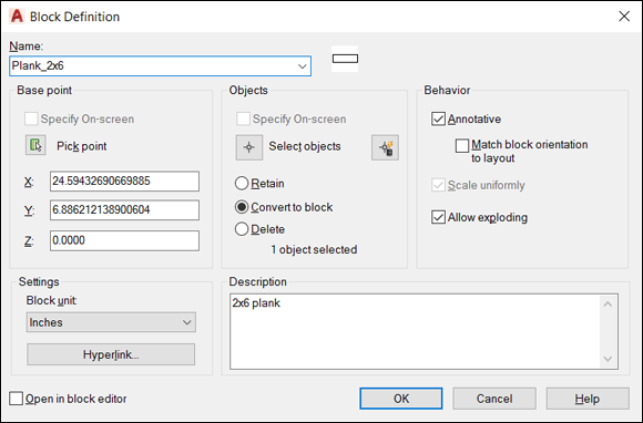
FIGURE 17-1: The Block Definition dialog box.

FIGURE 17-2: Building a block.
 When you define a block, you can include a special kind of variable text object: an attribute definition. When you insert a block that contains one or more attribute definitions, AutoCAD prompts you to fill in values for the text fields. Attributes are useful for elements such as variable title block information (sheet number and sheet title, for example), electric motor nameplate information, and symbols that contain different codes or callouts. I describe how to create and use attribute definitions later in this chapter.
Store commonly used symbol drawings in one or more specific folders that you set aside for this purpose. You can use one of these techniques to develop a library of frequently used symbols:
- Create a separate DWG file for each block. Insert these symbols by using the Insert command or by dragging them from Windows Explorer into the drawing area.
- Store several symbols as block definitions in one master drawing. Then use DesignCenter to import block definitions from this drawing whenever you need them.
- Use the WBLOCK (WriteBlock) command to extract a block definition from a drawing and then write a copy of it to disk as a new DWG file. Then you can insert the block definition into other drawings as required.
You can clean up a drawing by using the Wblock command to write an entire drawing to disk. It writes out only what it needs, but be careful because it also cleans out any unused custom layers, styles, and block definitions.
Inserting Blocks
AutoCAD provides a number of ways to insert a block or a whole drawing file, but the most commonly used and most flexible method is using the Insert button on the Ribbon menu. To insert a block, follow these steps:
-
Set an appropriate layer current, as described in Chapter 9.
Insert each block on a layer that has something to do with the block’s geometry or purpose: - If all objects in the block definition reside on one layer, you should usually insert the block on that layer.
- If the block geometry spans several layers, choose a suitable one to insert the block on. For example, a block that shows a gearbox made of geometry on layers named Casing, Armature, Shaft, and Fasteners might be inserted on a Motors layer.
 If any of the block definition’s geometry was created on Layer 0 (zero), the geometry inherits the color, linetype, and other object properties of the layer on which you insert the block. It’s like chameleons changing color to match their surroundings or politicians changing their position to match the day’s opinion polls. Any block components on layers other than layer 0 retain their respective layer’s properties.
 -
 On the Home tab of the Ribbon, click the Insert button on the Block panel.
A slideout panel drops down, displaying a thumbnail view of all block definitions in the current drawing.
- Click the block definition you want, and then click an insertion point for it.
If you want to do something fancier, in older AutoCAD releases you click the More Options button at the bottom of the thumbnail preview slideout panel to produce the Insert dialog box, as shown in Figure 17-3, left. In AutoCAD 2020, click the Recent Blocks button of the preview panel to launch the Blocks tool palette, as shown in 17-3, right.
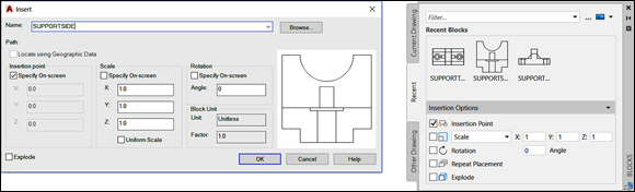
FIGURE 17-3: The Insert dialog box, with previous releases on the left and AutoCAD 2020 on the right.
I won’t bore you with the minute details of every option, but here are a few to give you an idea.
-
Enter the block definition name (or external filename) by using one of these methods:
-
Use the Name drop-down list to select from a list of block definitions in the current drawing or click the appropriate preview image.
The Name drop-down list supports autocomplete. As you begin to type the desired block name, AutoCAD searches through the drawing’s list of block names and finishes filling in the name for you.
-
Click the Browse button to select an external DWG file and have AutoCAD create a block definition from it.
Browse to any existing drawing and then insert it into the current drawing to create a new block definition in the host drawing. Note that nothing is magical about the incoming drawing. Any existing drawing can be inserted into any other drawing. The new definition retains no connection to the source drawing.Ah, but here’s the real magic of inserting an existing drawing to create a block definition. A great many manufacturers and suppliers have standard AutoCAD drawings of their products available, often online. Building a conveyor system and need a particular motor-gearbox unit? No need to draw it from scratch; just download it from the manufacturer’s website and plug it in.
You can use an external drawing to replace a block definition in the current drawing. If you click Browse and choose a file whose name matches the name of a block definition that’s already in the drawing, AutoCAD asks you to confirm the update and, if you agree, updates the block definition in the drawing with the current contents of the external file. In this process, block redefinition, AutoCAD automatically updates all block insertions that point to the block definition.
Earlier in the chapter, I mention the example of using a simplified representation of a bathtub during the design process and then replacing it with a detailed version later. Block redefinition by inserting an existing drawing is the fastest and easiest way to do this.
AutoCAD 2020 added one more bit of magic. Not only can you import an existing drawing, but you can also browse within it and just import the specific definition or definitions that you need. This feature can be accessed at the bottom of the drop-down panel from the Insert button of the Ribbon menu, or from the Other Drawing tab of the Blocks palette. -
-
Enter the insertion point, scale, and rotation angle of the block.
You can either select the Specify On-Screen check box in each area to specify the parameters onscreen at the command prompt or type the values you want in the text boxes in the Insertion Point, Scale, and Rotation areas.
Select the Uniform Scale check box to constrain the X, Y, and Z scaling parameters to the same value (which is what you want in almost all cases). - If you want AutoCAD to create a copy of the individual objects in the block instead of a block reference pointing to the block definition, select the Explode check box and click OK.
- If you selected the Specify On-Screen check box for the insertion point, scale, or rotation angle, specify these parameters by answering the prompts that appear on the command line.
After you insert a block, all the objects displayed in the block reference behave as a single object. When you select any object in the block reference, AutoCAD highlights all the objects in it.
AutoCAD gives you three more ways to insert a block:
- Drag and drop: Drag a DWG file from Windows Explorer and drop it anywhere in the current drawing window. AutoCAD then prompts you to choose an insertion point and (optionally) change the default scale factor and rotation angle. If you drag the drawing file to AutoCAD’s title bar, the file is instead opened as a new drawing.
-
The DesignCenter palette: Drag a block definition from the Blocks section of the DesignCenter palette and drop it into the current drawing window. Turn to Chapter 9 to find out how to use DesignCenter.
You can import Inventor part (IPT) and assembly (IAM) models directly into AutoCAD. Inventor is AutoCAD’s 3D parametric and associative sibling, intended primarily for mechanical design. Imported Inventor files come across as dumb 3D solids that lose their parametrics and associativity, but they can be modified and edited like any other AutoCAD 3D solid. I cover the 2D parametrics of AutoCAD in Chapter 19, and introduce you to 3D modeling in Chapters 21–23.
-
The Tool Palettes window: As is true of using the tool palette for hatching (as described in Chapter 15), you first must create and configure appropriate tools. The easiest method is right-clicking a drawing in DesignCenter and choosing Create Tool Palette. A new tabbed page is added to the Tool Palettes window, containing all block definitions from the drawing you right-clicked. Simply click and drag a tool to insert its corresponding block into a drawing.
Dragging blocks from a tool palette doesn’t give you the chance to specify a different insertion scale, nor can you use all the precision tools in AutoCAD to specify the insertion point precisely, so you may need to move the block into place after inserting it. You should first master the other block insertion methods described in this chapter, especially using the Insert dialog box and DesignCenter palette. Then if you find yourself inserting the same blocks frequently, consider creating a tool palette containing them. Check out the Add Content with DesignCenter topic in the AutoCAD online Help system for more information.
Although the preceding paragraph refers to the Tool Palettes window, palettes in AutoCAD aren’t like regular windows or dialog boxes. They’re modeless, so they can stay open while you carry out other tasks outside them. The official programmer-ese term for the palette is enhanced secondary window, or ESW. I stick with palette.
Be careful when you insert one drawing into another. If the host (or parent) drawing and the inserted (or child) drawing have different definitions for layers that share the same name, the objects in the inserted drawing take on the layer characteristics of the host drawing. For example, if you insert a drawing with lines on a layer named Walls that’s blue and dashed into a drawing with a layer named Walls that’s red and continuous, the inserted lines on the Wall layer turn red and continuous after they’re inserted. The same rules apply to linetypes, text styles, dimension styles, table styles, multileader styles, and block definitions that are nested inside the drawing you’re inserting. As you may recall, parents rule! Yeh, I wish.
To modify a block definition after you’ve inserted at least one instance of it, use the BEdit (Block Editor) command; choose Block Editor in the Block panel on the Home tab, or simply double-click a block insertion. Look up BEDIT in the online Help system in AutoCAD.
Attributes: Fill-in-the-Blank Blocks
You may think of attributes as the good (or bad) qualities of your significant other, but attributes in AutoCAD are fill-in-the-blank text fields that you can add to blocks. When you create a block definition and then insert it several times in a drawing, all the ordinary geometry elements (lines, circles, and regular text strings, for example) in all instances are exactly identical. Attributes provide a little more flexibility in the form of text strings that can be different in each block reference.
Suppose that you frequently designate parts in drawings by labeling them with distinct numbers or letters enclosed in a circle. If you want to create a block for this symbol, you can’t simply draw the number or letter as regular text by using the mText (T) or TEXT (DT) commands. When you create a block definition with a regular text object (for example, the letter A), the text string is the same in every instance of the block (always the letter A). That’s not much help in distinguishing the parts.
Instead, you create an attribute definition, which acts as a placeholder for a text string that can vary every time you insert the block. You include the attribute definition when you create the block definition. Refer to the “Creating Block Definitions” section, earlier in this chapter. Then every time you insert the block, AutoCAD prompts you to fill in an attribute value for each attribute definition.
When the block attribute value was first introduced, and for a long time afterward, it was limited to a single line of variable text with a maximum of 255 characters. AutoCAD 2008 and later supports multiline attributes; in addition to offering more than one line, multiline attributes have many of the formatting options of multiline text. For more information on creating and inserting blocks with multiline attributes, look up Define Block Attributes in the online Help system.
The AutoCAD documentation and dialog boxes often use the term attribute to refer indiscriminately to an attribute definition or an attribute value. I attribute a lot of the confusion about attributes to this sloppiness. Just remember that an attribute definition is the text field or placeholder in the block definition, and an attribute value is the specific text string you type when you insert the block.
Creating attribute definitions
You use the Attribute Definition dialog box to create attribute definitions. Clever, eh? The steps are similar to creating a text string except that you must supply a little more information. Create attribute definitions by following these steps:
- Change to the layer on which you want to create the attribute definition.
-
To run the ATTdef command, click Define Attributes in the Block panel slideout on the Home tab.
The Attribute Definition dialog box appears, as shown in Figure 17-4.
You rarely need to use any of the first four Mode settings (Invisible, Constant, Verify, or Preset). Leave them deselected. If you’re curious about what the modes do, hover the mouse pointer over an item; if that doesn’t give you enough information, click the Help button in the dialog box to find out more. -
Select or deselect the Lock Position check box.
If Lock Position is selected, the attributes can’t be relocated within the block reference and the whole thing is treated as a single object. Deselecting Lock Position allows attributes to be moved by dragging their grips, without moving the block reference as a whole.
-
Select or deselect the Multiple Lines check box.
Selecting Multiple Lines in the Mode area disables the Default text box and displays a button to open the Multiline Editor. By default, you don’t see the whole panoply of formatting options of the mText command’s In-Place Text Editor, but you can overscore or underscore text; and from a right-click menu, you can import text, assign a background mask, or choose from a number of other options. Setting the value of the system variable ATTIPE (Attribute In-Place Editor) to 1 enables all formatting options in the In-Place Text Editor. See the online Help system for more information.
-
In the Attribute area, type values for the tag (the unique identifier for the attribute), the user prompt, and the default value.
The name you type in the Tag text box can’t contain spaces. The Prompt and Default text boxes may contain spaces, though.Attribute values can include fields that update automatically, such as date, filename, and system variable settings.
-
(Optional) Click the Insert Field button to the right of the Default text box to insert a field.
See Chapter 13 for more information on fields.
-
(Optional) If you select the Multiple Lines check box in Step 4, click the Multiline Editor button (it shows three periods) to enter the multiline default attribute value and add any formatting; then click OK.
The text you enter in this step is the default value stored in the attribute definition, and you can change it when you insert the block.
-
In the Text Settings area, specify the justification, text style, annotative property, text height, rotation, and boundary width (the last for multiline attributes only).
The text properties for attribute definitions are the same as those for text objects, as covered in Chapter 13.
-
Select the Specify On-Screen check box to choose an insertion point for the attribute definition.
An attribute definition’s insertion point is similar to a text string’s base point. Remember to use snap, object snap, or another precision tool if you want the eventual attribute values to be located at a precise point.
- Click OK to create the attribute definition.
-
Repeat Steps 1–10 for any additional attribute definitions.
To create a series of attribute definitions in neat rows for a single block, create the first one by following Steps 1–9, and then select the Align Below Previous Attribute Definition check box for the subsequent definitions. To make a series of nonadjacent attributes, create the first one by using Steps 1–10, and then copy the first attribute definition and edit the copy by using the Properties palette. You can prevent attributes from being dragged around the block by selecting the Lock Position check box in the Attribute Definition dialog box.
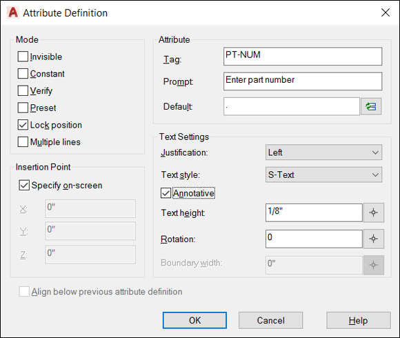
FIGURE 17-4: The Attribute Definition dialog box.
Defining blocks that contain attribute definitions
After you create one or more attribute definitions and any other geometry that you want to include in the block, you’re ready to create a block definition that contains them. Follow the steps in the earlier section “Creating Block Definitions.” At Step 4 in that section, you can select any attribute definitions before or after you select the other geometry. However, you should select each attribute definition one by one (clicking each attribute definition rather than selecting multiple attributes with a selection window) in the order you want the attribute value prompts to appear in the Edit Attributes dialog box. (See Figure 17-5.) If you don’t select the attributes one by one, the block and attributes still work, but the order of the attribute prompts in the Edit Attributes dialog box may not be what you want.
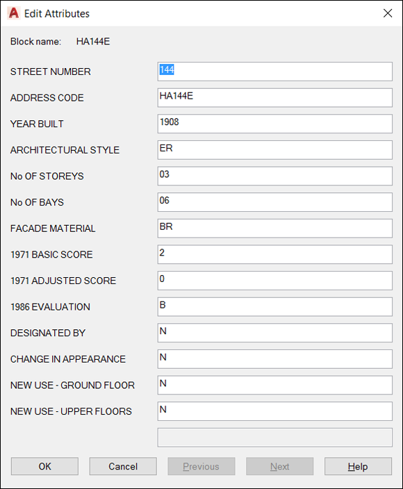
FIGURE 17-5: The Edit Attributes dialog box.
You can use the Block Attribute Manager to reorder the attribute definitions in a block definition. Choose Attribute ⇒ Block Attribute Manager in the Block panel slideout on the Home tab to start the BATTMAN command. Yes, Robin, there actually is such a command name. You can also use this dialog box to edit other attribute definition settings such as the prompt, text style, or layer.
Inserting blocks that contain attribute definitions
After you create a block definition that contains attribute definitions, you insert it the same way you insert any other block. Follow the steps in the earlier section “Inserting Blocks.” At the end of the steps, AutoCAD displays the Edit Attributes dialog box, as shown in Figure 17-5. The dialog box contains one row for each of the attribute definitions and has any default values filled in. You simply edit the values and then click OK.
The ATTDIA (ATTribute DIAlog box) system variable controls whether AutoCAD prompts for attribute values in a dialog box (ATTDIA=1) or at the command line (ATTDIA=0). If you insert a block and see command line prompts for each attribute value, type a value and press Enter for every attribute value you want to set. When you return to the command prompt, type ATTDIA, press Enter, type 1, and press Enter again. When you insert blocks with attributes into this drawing in the future, AutoCAD displays the Edit Attributes dialog box instead of prompting you at the command line.
Editing attribute values
After you insert a block that contains attributes, you can edit the individual attribute values in that block reference with the EATTEDIT command. Click the Single drop-down button in the Block panel on the Home tab and click any object in the block reference. AutoCAD displays the Enhanced Attribute Editor dialog box with the current attribute values, as shown in Figure 17-6. The most common attribute editing operation is to edit the text value, which is the text string that appears in the block reference. You also can change properties of the attributes, such as layer and text style.
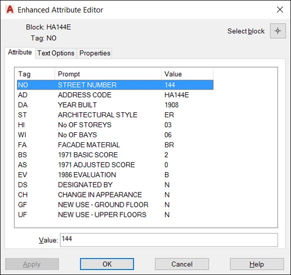
FIGURE 17-6: The Enhanced Attribute Editor dialog box.
Many people use attributes only in the way I describe in this chapter, as fill-in-the-blank text fields in blocks. But attributes also can work with data extraction tools. For example, you can export attribute values, such as part numbers and quantities, to a table object in AutoCAD or to a text, spreadsheet, or database file for analysis or reporting.
Extracting data
![]() Selecting Extract Data from the Linking & Extraction panel on the Insert tab of the Ribbon starts the Data Extraction Wizard. You can find out much more about this specialized function in the online Help system. Check out User’s Guide ⇒ Share Data between Files ⇒ Extract Data from Drawings and Spreadsheets. And if you use AutoCAD LT and don’t have this wizard, you can still extract attribute information to space- or comma-delimited text files by using the Attribute Extraction dialog box. These files can be imported into spreadsheets and database programs for further processing. For more information, visit the online Help system.
Selecting Extract Data from the Linking & Extraction panel on the Insert tab of the Ribbon starts the Data Extraction Wizard. You can find out much more about this specialized function in the online Help system. Check out User’s Guide ⇒ Share Data between Files ⇒ Extract Data from Drawings and Spreadsheets. And if you use AutoCAD LT and don’t have this wizard, you can still extract attribute information to space- or comma-delimited text files by using the Attribute Extraction dialog box. These files can be imported into spreadsheets and database programs for further processing. For more information, visit the online Help system.
Exploding Blocks
In a regular block definition (not a dynamic block), the objects in each block reference act like a well-honed marching squadron: If you move or otherwise edit one object in the block reference, all objects move or change in the same way. Usually this cohesion is a benefit, but occasionally you need to break up the squadron to modify a single object and not affect the others.
![]() To explode a block reference into individual objects, click Explode in the Modify panel on the Home tab; or type X, press Enter, and select the block reference. When you explode a block reference, AutoCAD replaces it with all objects (the lines, polylines, and arcs, for example) specified in the block definition. You then can edit the objects individually or perhaps use them to make more block definitions. Only the block you select is exploded.
To explode a block reference into individual objects, click Explode in the Modify panel on the Home tab; or type X, press Enter, and select the block reference. When you explode a block reference, AutoCAD replaces it with all objects (the lines, polylines, and arcs, for example) specified in the block definition. You then can edit the objects individually or perhaps use them to make more block definitions. Only the block you select is exploded.
When you explode a block that contains attributes, the attribute values revert to become attribute definitions (usually not a desirable change). If you truly need to explode the block reference, you can erase the attribute definitions and draw regular text strings in their place. If you’ve installed the AutoCAD Express Tools (not available in AutoCAD LT), you can perform this task automatically with the BURST command: Type BURST and press Enter.
Both AutoCAD and AutoCAD LT have an NCOPY command that you can use to copy objects contained within blocks without having to explode the block. AutoCAD users who are familiar with the Express Tools may already be familiar with NCOPY; the command is now in the core of the program and therefore available to LT users. In both versions, you can find the Copy Nested Objects tool in the Modify panel slideout on the Home tab or simply type NCOPY.
Purging Unused Block Definitions
Each block definition increases the size of the DWG file, as do other named objects, such as layers, text styles, and dimension styles. In the case of a large, complex block definition, the size increase can be significant. If you delete (or explode) all block references that point to a particular block definition, that block definition no longer serves any purpose.
![]() You should run the PUrge command periodically in each drawing to purge unused block definitions. Click the Application button to open the Application menu, choose Drawing Utilities on the left side, and then choose Purge to display the Purge dialog box. Click the Purge All button to purge all unused named objects in the current drawing.
You should run the PUrge command periodically in each drawing to purge unused block definitions. Click the Application button to open the Application menu, choose Drawing Utilities on the left side, and then choose Purge to display the Purge dialog box. Click the Purge All button to purge all unused named objects in the current drawing.
PUrge isn’t only for blocks: You can also remove empty layers, blank text strings, zero-length lines, empty groups, and unused style definitions. In Figure 17-7, the Purge dialog box shows the unused dimension, multileader, and text styles that can be removed from this drawing with a click of the Purge All button.

FIGURE 17-7: Purging the drawing of unneeded named objects.
Figure 17-7 shows the rearranged Purge dialog box introduced in AutoCAD 2020. The dialog box in earlier releases has the same basic functionality but it’s arranged differently.
Note the Purge Nested Items check box. Some items may not become unused until other items are purged. For example, a block definition can contain one or more other block definitions as components, and they in turn can contain other components. If the parent contains the only use of a child or grandchild, purging the parent will orphan the child and so on. When Purge Nested Items is selected, AutoCAD tunnels down through the nestings, looking for new orphans. These may include block definitions or items such as layer, text style, and dimension style specifications.
As I mention earlier in this chapter, you can insert any existing drawing into the current one where it becomes a block definition. In a common scenario, you know that another drawing of a 1,000-room hotel contains a block definition of a bathtub you want to use in the master bathroom of a house drawing. No problem: Simply insert the hotel drawing into the house drawing, and then erase or delete the hotel drawing insertion. The drawing now contains a block definition for the bathtub. Oops! Here’s a problem. The house drawing file size has suddenly increased to government-spending numbers because it now contains the hotel drawing and all its block definitions, along with elements such as layer, text style, and dimension style specifications. It’s PUrge to the rescue!