Chapter 8
Preciseliness Is Next to CADliness
IN THIS CHAPTER
![]() Typing coordinates at the keyboard
Typing coordinates at the keyboard
![]() Getting to know the AutoCAD coordinate systems
Getting to know the AutoCAD coordinate systems
![]() Snapping to object features
Snapping to object features
![]() Using other precision drawing and editing techniques
Using other precision drawing and editing techniques
Drawing precision is vital to good CAD drafting practice, even more than for manual drafting. Accuracy, of course, is vital to both types of drafting. If you’re sketchy on the difference between accuracy and precision, look ahead to the “CAD precision versus accuracy” sidebar in this chapter. If you think CAD managers become tense when you assign properties directly to objects instead of ByLayer (see Chapter 9), wait until someone — I sincerely hope it’s not you — fails to use precision techniques when creating drawings in AutoCAD.
 You must draw with precision, at least until you see Chapter 19. Now there’s a teaser for you. Typically, the only point you select at random in a drawing is the first one. Then virtually all line starts and lengths or ends, and all circle and arc centers and radii or diameters, for example, should be specified using exact keyboard input or a suitable object snap.
Controlling Precision
In AutoCAD, a lack of precision makes editing, hatching, and dimensioning tasks much more difficult and time consuming. Keep these facts in mind:
- Small errors in precision in the early stages of creating or editing a drawing often significantly affect productivity and precision later.
- CAD drawings are often used for much more than giving pictures to someone. If the drawings have been properly created, they can also be queried for factors such as size, area, and quantity.
- Drawings may guide manufacturing and construction projects; drawing data may drive automatic manufacturing machinery such as CNC machining and 3D printing. Huge amounts of money, and even lives, can ride on a drawing’s precision.
In recognition of these facts, a passion for precision permeates the profession. Precision is one characteristic that separates CAD from ordinary illustration-type drawing work. The sooner you get fussy about precision in AutoCAD, the happier everyone is.
When I talk about drawing elements precisely, I mean using precision techniques and tools to specify points and distances with as much exactness as the program allows. Luckily, AutoCAD provides a comprehensive package of tools for this task. Table 8-1 lists the more important AutoCAD precision techniques, along with visual cues to the status bar buttons you click to toggle certain features on and off. Note that this list omits status bar buttons that don’t directly affect drawing precision directly.
TABLE 8-1 Precision Tools and Techniques
|
Technique |
F Key |
Status Bar Button |
What It Does |
|
Infer constraints |
— |
|
Applies geometric constraints at specific pick points (not in AutoCAD LT), as covered in Chapter 19 |
|
Snap mode |
F9 |
|
Forces the cursor to move on an imaginary grid of equally spaced hot spots |
|
PolarSnap |
— |
|
Forces the cursor to move specific distances along polar tracking angles |
|
Grid display |
F7 |
|
Displays a nonprinting reference grid of lines or dots arranged in rows or columns |
|
Ortho mode |
F8 |
|
Forces the cursor to move horizontally or vertically from the previous point |
|
Polar tracking |
F10 |
|
Causes the cursor to jump to specified angles |
|
Object snap |
F3 |
|
Lets you pick specific points on existing drawing objects without having to initiate a specific snap mode every time |
|
3D Object snap |
F4 |
|
Lets you pick specific points on existing 3D objects multiple times (not in AutoCAD LT) |
|
Object snap tracking |
F11 |
|
Causes the cursor to locate new points based on one object snap point (or more) |
|
Object snap overrides |
— |
— |
Lets you pick specific points on existing drawing objects one time only |
|
Coordinate input |
— |
— |
Lets you type exact X,Y or polar coordinates |
|
Direct distance entry |
— |
— |
Lets you locate a point by moving the cursor to show the direction and then typing a distance |
You can switch many of the buttons — and hence their functionality — on and off by using the F keys. Table 8-1 lists the icons and F keys, where appropriate, for each button.
 Precision is especially important when you’re drawing or editing geometry — the lines, arcs, and other elements that make up whatever you’re representing in the CAD drawing. Precision placement usually is less important with notes, leaders, and other annotations that describe, not show.
To use object snap tools, follow these steps:
-
Make sure all status bar buttons are turned off.
They should have gray, not blue, icons.
- Start the Line command.
- Pick three points to draw two sides of a triangle.
-
Draw the third side of the triangle.
Pick a point as close as you can to the start of the first line (that is, the first point you picked). Don’t use the Close option.
-
Press Enter to complete the command.
Pressing the spacebar is usually faster than pressing Enter. - Right-click the Object Snap button and choose Settings.
-
Deselect all items except for Endpoint and Object Snap On. Click OK.
With these two settings, you’re turning on object snap functionality and one of the object snap modes (Endpoint).
- Start the Line command again.
- Hover the cursor over the first line so that a green square box lights up at the end of the line closest to its starting point. Pick the line at this point.
-
Repeat Step 9 for the ending point of the third line and then press Enter.
The second green square box may look like it's in the exact location as the first, but it probably isn’t.
-
Enter Zoom Object Last and press Enter.
AutoCAD zooms in to display a tiny line segment — the last line you drew. The triangle now consists of four lines. The last line may be quite small, but it is a fourth line nonetheless.
- Enter Zoom Previous.
-
Repeat Steps 8–10, but select two lines that form one of the other two vertices of the triangle.
Press F2 to expand the command line, where AutoCAD reports that it created a
“zero-length line”. Obviously, the two lines now touch perfectly because the last one snapped like a magnetic attraction to the endpoint of the first line. Okay, it was the start point, but I’m sure that you … get the point.If you were able to make the first and third lines touch at the limit of AutoCAD’s 16-place accuracy, you should throw away this book and buy every lottery ticket you can find.
If you had tried to use the original three lines to control a computer numerically controlled (CNC) milling machine, you would have had problems at the final apex. You need to draw the triangle using the Close option of the Line command or the endpoint object snap.
Before you draw objects, always check the status bar buttons and set them according to your need for precision.
- ON: The button icon is blue.
- OFF: The button icon is light gray.
Understanding the AutoCAD Coordinate Systems
Every point in an AutoCAD drawing file can be identified by its X,Y,Z coordinates. In most 2D drawings, the Z-coordinate value is 0.0 This system of coordinates is referred to in AutoCAD as the world coordinate system, or WCS.
Keyboard capers: Coordinate input
The most direct way to enter points precisely is to type numbers with the keyboard. AutoCAD uses these keyboard coordinate entry formats:
- Absolute Cartesian (X,Y) coordinates in the form X,Y (for example, 7,4): This format is the default for input at the command line.
-
Relative X,Y coordinates in the form @X,Y (for example, @3,2): Defines a new point that is X units horizontally (3, in the example) and Y units vertically (2, in the example) away from the current point.
 Dynamic Input mode works with relative coordinates even though the @ prefix isn’t used.
 -
Relative polar coordinates in the form @distance<angle (for example, @6<45): Defines a new point that is the specified distance (6, in the example) units away from the current point at the specified angle (45 degrees, in the example) from the origin.
If you want to use absolute coordinates while using Dynamic Input mode, use the # (pound) sign prefix.
AutoCAD nearly always measures angles counterclockwise from the positive X-axis (east), except for surveyors. You know who you are, and you know how your angles work!
Introducing user coordinate systems
Many times, you can conveniently define an additional coordinate system (or “roll your own”) to more easily create drawings. This non–world coordinate system is known as a user coordinate system.
Why would you want to diverge from the standard WCS? Well, the most common reason is that it’s much easier to calculate and enter coordinates if they’re based on the plane you want to work on in 3D. Suppose that you’re modeling an old-fashioned, wedge-shaped rubber doorstop and you want to add the manufacturer’s logo to the sloping surface of the wedge. It isn’t easy if you stay in the WCS, but AutoCAD lets you set a new UCS based on that sloping surface. After the UCS is made current, you draw in it just as you draw in the WCS. I have more to say about UCSs in 3D in Chapter 21.
Think of the real world. A specific latitude and longitude (WCS) always identifies the same point, but the actual location for a description, such as “the corner of 33rd and Main,” depends on which city you're in (UCS).
Although originally intended for 3D work, a UCS can be useful in two dimensions as well. The WCS assumes that the north direction is straight up (90 degrees, according to the AutoCAD default settings), but you may be working on a building layout where one wing is at a 37.8 degree angle to the other. No problem: Simply create a UCS that’s aligned appropriately. You can look up this process in the online Help system (this book has only so many pages, after all), but here’s a quick hint: Click the UCS icon in the lower-left corner of the screen to make grips appear at the origin and the ends of the axis indicators. Then drag the icon by its grips to set a new UCS. I cover this feature more fully in Chapter 21.
Creating a UCS by typing options at the command line is generally easier than using the UCS Manager dialog box, but after they’re created, they’re easier to manage from the UCS dialog box. Type UCSMAN and press Enter to display it.
Drawing by numbers
AutoCAD locates absolute X,Y coordinates with respect to the 0,0 point (otherwise known as the origin) of the drawing — usually, its lower-left corner. AutoCAD locates relative X,Y coordinates and relative polar coordinates with respect to the previous point you picked or typed. Figure 8-1 demonstrates how to use all three coordinate formats to draw a pair of line segments that start at the absolute coordinates 2,1 and then move to the right 2 units and up 1 unit (@2,1) relative to the first point, and then (relative to that point) move 2 units at an angle of 60 degrees (@2<60). Note in particular how the first two coordinate pairs use the same numbers (2,1) but the second pair defines a different point because of the leading @ symbol.

FIGURE 8-1: Coordinating from the keyboard.
You can find out the X,Y location of the cursor by moving it around in the drawing area and reading the coordinate values in the status bar. The X,Y coordinates should change as you move the cursor. If the coordinates don’t change, click the drawing coordinates area until you see <Coords on> in the command line.
If you’re using the full version of AutoCAD, you may have noticed that three numbers are at the left end of the status bar. AutoCAD LT is numerically challenged and only has two. AutoCAD is showing you the X,Y coordinates of the cursor and the current elevation (the Z value). However, in 2D drafting, the Z value is or should be 0 (zero), so you can continue calling them X,Y coordinates.
Although it isn’t apparent at first, AutoCAD has, in fact, four coordinate display modes. Clicking the coordinates readout cycles through these modes:
- Off (
<Coords off>): The status bar coordinate readout is dimmed, and the coordinate values don’t update until you pick a point. - On, showing X,Y coordinates (
<Coords on>): The coordinate readout is bright and the absolute X,Y coordinates update continuously as you move the cursor. If no command is active, clicking the coordinates readout alternates between this mode and<Coords off>. - On, showing polar coordinates (
<Coords on>): This mode, which displays distance and angle relative to the last point picked rather than absolute X,Y values, appears only if a command is active and AutoCAD is waiting for you to pick a point. - On, showing geographic coordinates (
<Coords on>): This mode displays coordinates as latitude and longitude values, but it can be used only after you set the drawing’s geographic location with the (what else?) GEOGRAPHICLOCATION command.
If you start a command such as Line, pick a point, and then click the Coordinates area a few times, the display changes from coordinates Off to live absolute coordinates (X,Y position) to live polar coordinates (distance and angle from the previous point).
If you’re working in AutoCAD’s architectural or engineering units, the default unit of entry is inches, not feet. Here are some guidelines for entering numeric values when you work with feet and inches:
-
To specify feet, you must enter the apostrophe (‘) symbol for feet after the number:
6’ is 6 feet.
-
To separate feet from inches (as architects often do), enter a dash:
6’-6” is 6 feet, 6 inches.
-
When you enter coordinates and distances, both the dash and the inch mark are optional:
6’6” and 6’6 are the same as 6’-6”.
-
To type a coordinate or distance that contains fractional inches, you must enter a dash — not a space — between the whole number of inches and the fraction:
6’6-1/2 (or 6’-6-1/2) represents 6 feet, 6-1/2 inches.
-
To enter partial inches (if all this dashing about confuses you), use decimals instead:
6’6.5 is the same as 6’6-1/2” to AutoCAD, whether you’re working in architectural or engineering units.
To check the accuracy (or precision) of objects that are already drawn, the MEAsuregeom command is a one-stop shop where you can query drawing objects for distances, angles, areas, and other geometric or locational information. You can find the command on the Utilities panel of the Home tab — look for an icon with a yellow ruler. Click the down arrow below the ruler to see a drop list of measuring operations.
The LIst command also tells you all you need to know about selected objects.
Grabbing an Object and Making It Snappy
After you’ve drawn a few objects precisely in a new drawing, the most efficient way to draw more objects with equal precision is to grab specific, geometrically precise points, such as endpoints, midpoints, or quadrants, on the existing objects. Every object type in AutoCAD has at least one of these points, and you can snap to them precisely as you draw by using object snaps (osnaps).
AutoCAD provides two ways to use an object snap:
- Object snap override: Active for a single pick.
- Running object snap: Remains in effect until you turn it off.
AutoCAD (but not AutoCAD LT) has a suite of object snaps specifically for working in 3D. Although I cover them fully in Chapter 21, I point them out here because the 3D Object Snap status bar button sits next to the standard Object Snap button, and it isn’t easy to distinguish them. In this section, you use the regular Object Snap button — it shows the square with the little spot in the upper-left corner, not the 3D-looking box with the little green spot on one front corner.
Grabbing points with object snap overrides
Here’s how to draw precise lines by using object snap overrides:
- Open a drawing containing some geometry, or start a new drawing and create some.
-
 Turn off running object snap mode by clicking the Object Snap (F3) button on the status bar until the button appears to be dimmed and
 <Osnap off>appears in the command line. Although you can use object snap overrides while running object snaps are enabled, I recommend that you turn off running object snaps while you’re becoming familiar with object snap overrides. After you get the hang of each feature separately, you can use them together. -
Start the Line command by clicking the Line button in the Draw panel on the Ribbon or by typing Line (or L) and pressing Enter.
AutoCAD prompts you to select the starting point of the line:
Specify first point: -
Hold down the Shift key, right-click anywhere in the drawing area, and release the Shift key.
The Object Snap menu appears, as shown in Figure 8-2.
-
Choose an Object Snap mode, such as Endpoint, from the Object Snap menu.
The Object Snap menu disappears and the command line displays an additional prompt indicating that you’ve directed AutoCAD to seek out, for example, the endpoints of existing objects:
_endp of: -
Move the cursor slowly around the drawing, pausing over various lines and other objects. Don’t click yet.
When you move the cursor near an object with an endpoint, a colored square icon appears at the endpoint, indicating that AutoCAD can snap to that point. If you stop moving the cursor for a moment, a tooltip displaying the Object Snap mode (for example,
Endpoint) appears, to reinforce the idea. -
Click when the ENDpoint object snap square appears on the point you want to snap to.
AutoCAD snaps to the endpoint, which becomes the first point of the new line segment that you’re about to draw. The command line prompts you to select the other endpoint of the new line segment:
Specify next point or [Undo]:When you move the cursor around the drawing, AutoCAD no longer seeks out endpoints, because object snap overrides last for only a single pick. You can use the Object Snap right-click menu again to snap the other end of the new line segment to another point on an existing object.
-
Display the Object Snap menu again (refer to Step 4). Then choose another Object Snap mode, such as MIDpoint, from the Object Snap menu.
The command line displays an additional prompt indicating that you directed AutoCAD to seek, for example, midpoints of existing objects:
_mid of:When you move the cursor near the midpoint of an object, a colored triangle appears at the snap point, as shown in Figure 8-3. Each object snap type (such as ENDpoint, MIDpoint, and INTersection) displays a different symbol. If you stop moving the cursor, the tooltip text reminds you of what the symbol means.
-
Draw additional line segments by picking additional points. Use the Object Snap right-click menu to specify a single object snap type before you pick each point.
Try the INTersection, PERpendicular, and NEArest object snaps. If the drawing contains arcs or circles, try Center and Quadrant.
- When you finish working with object snap overrides, right-click anywhere in the drawing area and choose Enter from the menu or press the spacebar to end the Line command.
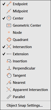
FIGURE 8-2: The Object Snap right-click menu.

FIGURE 8-3: A snappy line.
You can activate object snap overrides during a command by entering the first three letters of a mode at the command line whenever AutoCAD is asking you to select a point.
Snap goes the cursor
Table 8-2 explains the subtleties of the different object snap modes.
TABLE 8-2 Object Snap Modes
|
Mode |
What It Does |
|
ENDpoint |
Snaps to the nearest end of an open drawing object, such as a line, an arc, a polyline segment, or an elliptical arc. |
|
MIDpoint |
Snaps to the nearest midpoint of an open drawing object, such as a line, an arc, a polyline segment, or an elliptical arc. |
|
CENter |
Snaps to the center of a circle, an arc, or an elliptical arc. |
|
Geometric CEnter |
Snaps to the center of gravity of a closed polyline or a spline. |
|
NODe |
Snaps to a point object, or to the definition point of a dimension, or to the insertion point of dimension text. |
|
QUAdrant |
Snaps to the quadrant points (0, 90, 180, or 270 degrees) of a circle or an arc, or to the ends of the major or minor axis of an ellipse or an elliptical arc. |
|
INTersection |
Snaps to the point where two drawing objects cross or meet. |
|
EXTension |
Displays a temporary extension line when you pass the cursor over the end of an object so you can snap to a point along this temporary extension. |
|
INSertion |
Snaps to the insertion point of text, mtext, or a block insertion. |
|
PERpendicular |
Snaps to the point that forms a right angle between the start point and the object being selected. Perpendicular is not confined to the common image of a horizontal line with a vertical line attached at one end. Lines do not need to be horizontal and vertical nor do they even need to touch to be perpendicular. A line can also be perpendicular to a circle, an ellipse, or even to the sinuous curve of a spline. |
|
TANgent |
Snaps to the tangent of an arc, a circle, an ellipse, an elliptical arc, a polyline arc, or a spline. |
|
NEArest |
Snaps to the point on the selected object that is the shortest distance from the starting point. |
|
APParent Intersection |
Snaps to the point where objects appear to intersect in the current view, even when they don’t actually intersect in 3D. |
|
PARallel |
Creates a new line segment, polyline segment, ray, or xline that is parallel to an existing linear object. ORTHO mode must be turned off before using the PARallel object snap. |
|
M2P |
Snaps to a point midway between two other points. |
Deferred object snaps are turned on automatically when the first point you pick doesn’t fully satisfy the current object snap. Following are two examples:
- Deferred tangent: You would normally draw a line from a first point to a TANgent point on a circle. On the other hand, if you select the circle first and then select the second point, the line is drawn outward from the circle to the point. This technique can be used to draw a line that is tangent to two non-collinear circles.
- Deferred perpendicular: You normally draw a line from a first point to a PERpendicular point on a circle. On the other hand, if you select the circle first and then select the second point, the line is drawn outward from the circle to the point. This technique can be used to draw a line that is perpendicular to two non-collinear circles.
Right-clicking and Shift+right-clicking do different things in the drawing area:
- Right-click: Displays menu options for the current command (or common commands and settings when no command is active).
- Shift+right-click: Always displays the same Object Snap menu.
Running with object snaps
Often, you use an object snap setting (such as ENDpoint) repeatedly. Use running object snaps to address this need.
Follow these steps to set a running object snap:
-
Right-click the Object Snap button on the status bar.
The Object Snap menu appears, as shown in Figure 8-4.
Many status bar buttons display shortcut menus when you right-click, as shown in Figure 8-4. Object Snap and Object Snap Tracking both display the menu of running object snaps. Many settings, including all running Object Snap types, can be set by clicking a menu item.
-
Click in the menu to select one or more Object Snap settings.
Active running Object Snap settings show a check mark beside the icon (see Figure 8-4).
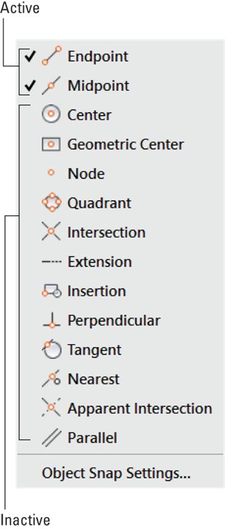
FIGURE 8-4: Grabbing multiple object features is an osnap.
You click the Object Snap button on the status bar or press the F3 key to toggle Running Object Snap mode. After you turn on this mode, AutoCAD hunts for points that correspond to the object snaps you selected on the Object Snap button’s right-click menu. As with object snap overrides, AutoCAD displays a special symbol — such as a square for an ENDpoint object snap — to indicate that it has found an object snap point. If you keep the cursor still, AutoCAD also displays a tooltip that lists the object snap point type.
Use object snap overrides or running object snaps to enforce precision by ensuring that new points you pick coincide exactly with points on existing objects. In AutoCAD, you can’t let points almost coincide or look like they coincide. You lose points, both figuratively and literally, if you don’t use object snaps or another precision technique covered in this chapter to enforce precision.
When using earlier releases of AutoCAD, applying crosshatching rapidly became impossible if the boundary of the area you were hatching had even microscopic leaks. Current releases have a Hatch Gap option to overcome this problem, but using this option is almost never correct. Although you can crosshatch a leaky area, you will run into far greater problems downstream. For example, leaky geometry will create havoc if you try to use it to program a CNC machining center.
Most, but not all, object snap overrides have running object snap equivalents. For example, ENDpoint, MIDpoint, and CENter work as either overrides or running object snaps, but M2P (Mid between 2 Points) works only in override mode.
Other Practical Precision Procedures
The following list describes additional AutoCAD precision techniques (refer to Table 8-1):
-
 Snap: If you turn on Snap mode, AutoCAD constrains the cursor to an imaginary rectangular grid of points at the spacing that you’ve specified when AutoCAD prompts you to specify a point.
When you enable Snap mode, at first it seems to be broken because the cursor doesn’t snap to the imaginary grid but travels freely. Snap mode becomes active only when the program asks you to pick a point.
Follow these steps to turn on Snap mode:
- Right-click the Snap Mode button on the status bar.
-
Choose Settings.
The Snap and Grid tab in the Drafting Settings dialog box appears.
- Enter a snap spacing in the Snap X Spacing field and click OK.
Click the Snap Mode button on the status bar or press F9 to toggle Snap mode off and on.
Usually, you can turn on Snap mode all the time, set at the usual smallest measurement increment. For example, to design doorknobs, I set it to 0.001, whereas an architect might set it to 1/8”. Now, I know that even randomly selected points have the degree of accuracy I want.You can switch between Grid Snap (snap points in rows and columns) and Polar Snap (snap points based on distances and angles) by using the Snap mode button’s shortcut menu. See the Polar Snap bullet for more information.
-
 Ortho: Using Ortho mode forces the cursor to move horizontally or vertically relative to the current coordinate system’s X- and Y-axes. To toggle Ortho mode, click the Ortho Mode button on the status bar or press F8. You can also hold down the Shift key to temporarily go in and out of Ortho mode. Because technical drawings often include lots of orthogonal lines, you may use Ortho mode a lot — but take a close look at polar tracking as well.
You know you’ve been using AutoCAD too long when the police officer asks you to walk a straight line and you reply, “No problem. Can you press F8 please?”
-
Direct distance entry (DDE): This point-and-type technique is an easy and efficient way to draw with precision. You simply point the cursor in a particular direction, type a distance value at the command line, and press Enter. You can use DDE at any time the cursor is anchored to a point, and the command line or Dynamic Input tooltip prompts you for another point or a distance.
You usually use DDE with polar tracking turned on to specify distances in particular directions (for example, in angle increments of 45 degrees). You can also combine DDE with Ortho mode to specify a distance in an orthogonal direction (0, 90, 180, or 270 degrees).
-
 Object snap tracking: This feature extends running object snaps so that you can locate points based on more than one object snap point. For example, you can define a point at the center of a square by tracking to the MIDpoints of two perpendicular sides. Click Object Snap Tracking on the status bar or press F11 to toggle Object Snap Tracking.
You can locate points based on more than one object snap point. Follow these steps:
- Draw a rectangle with the RECtang command.
- Right-click the Object Snap button, choose Settings, turn on MIDpoint, and then click OK.
- Make sure Object Snap (F3) and Object Tracking (F11) are turned on.
- Start the Circle command.
- Move the cursor close to the middle of the bottom line of the rectangle until the green triangle osnap marker appears. Don’t pick this point.
- Move the cursor vertically and note that the green triangle disappears to be replaced by a green + sign, and a vertical dotted green line appears.
- Move the cursor close to the middle of one of the vertical lines of the rectangle until the green triangle osnap marker appears. Don’t pick this point either.
- Move the cursor horizontally until the two dotted green lines cross and an X appears, along with a midpoint tooltip, as shown in Figure 8-5.
- Click this point to define the center of a circle that is exactly in the middle of the rectangle.
You can use this same technique to transfer points from a front view to a top view or to a side view without having to use construction lines.
-
 Polar tracking: When you turn on polar tracking, the cursor jumps to increments of the angle you specified in the Drafting Settings dialog box or chose on the right-click menu. When the cursor jumps, a tooltip label starting with Polar: appears. Right-click the Polar Tracking button on the status bar and choose the Settings option to display the Polar Tracking tab in the Drafting Settings dialog box. Select an angle from the Increment Angle drop-down list and then click OK. Click the Polar Tracking button on the status bar or press F10 to toggle Polar Tracking mode.
Remember that you can set a predefined polar tracking angle by right-clicking the Polar Tracking button and choosing an angle from the menu. If you want to add an angle that isn’t on the list, you have to click Settings to open the Drafting Settings dialog box.
Polar and Ortho modes are mutually exclusive. Turning on one turns off the other. -
PolarSnap: You can force polar tracking to jump to specific incremental distances along the tracking angles by changing the snap type from Grid snap to PolarSnap. For example, if you turn on polar tracking and set it to 45 degrees, and then turn on PolarSnap and set it to 2 units, polar tracking jumps to points that are at angle increments of 45 degrees and distance increments of 2 units from the previous point. PolarSnap has a similar effect on Object Snap tracking.
To activate PolarSnap, right-click the Snap Mode button and choose PolarSnap from the menu. To specify a PolarSnap distance, follow these steps:
- Right-click the Snap button on the status bar.
-
Choose Settings.
The Snap and Grid tab on the Drafting Settings dialog box appears.
- Select the PolarSnap radio button, type a distance in the Polar Distance text box, and then click OK.
When you want to return to ordinary rectangular snap, as described at the beginning of this list, right-click the Snap Mode button and choose Grid Snap from the menu.
- Temporary override: Settings such as Snap, Ortho, and Polar remain on until you turn them off. You can also use a temporary override, which lasts only as long as you hold down its key or key combination. For example, when Ortho mode is turned off, holding down the Shift key puts AutoCAD into Ortho mode temporarily for as long as you press Shift. For additional information, see the online Help system.
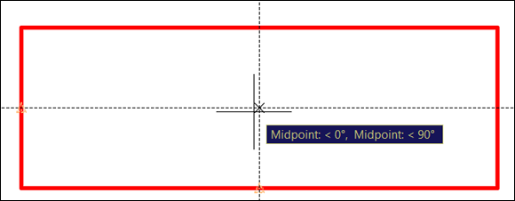
FIGURE 8-5: Using Object Snap Tracking to find the exact middle of a rectangle.
If you’re new to AutoCAD, its wide range of precision tools may seem overwhelming. Rest assured that there’s more than one way to use the program’s precision tools. You can make perfectly precise drawings without using every single implement in the AutoCAD precision toolkit. I recommend these steps:
- Become comfortable with typing coordinates, Ortho mode, direct distance entry, and Object Snap overrides.
- Become familiar with running object snaps, and experiment with Snap mode.
- After you’re comfortable using all these precision features, experiment with polar tracking, PolarSnap, and object snap tracking.
Snap constrains the cursor to locations whose coordinates are multiples of the current snap spacing, and it works whether or not the drawing has objects in it. Object snap (osnap) enables you to grab points on existing objects, whether or not those points happen to correspond with the snap spacing.
What happens if some of your drawing-with-precision choices seem to contradict each other? The answer is simple: AutoCAD uses the one that requires the greater effort to initiate. That is, Snap is overridden by Object Snap, which is overridden by a snap override, which is overridden by the keyboard entry of points or distances.