Chapter 9
Manage Your Properties
IN THIS CHAPTER
![]() Managing object properties, such as color, linetype, and lineweight
Managing object properties, such as color, linetype, and lineweight
![]() Managing layers
Managing layers
![]() Copying layers and other named objects between drawings with DesignCenter
Copying layers and other named objects between drawings with DesignCenter
Contrary to what you might believe, managing properties has nothing to do with real estate holdings. CAD programs are different from other drawing programs in that you have to pay attention to little details, such as object properties or the precision of points that are specified when you draw and edit objects. If you ignore these details and start drawing, you’ll produce a mess of sloppy geometry that’s difficult to edit, view, and plot.
This chapter introduces object properties — one set of AutoCAD tools and techniques that can help prevent you from making CAD messes. Chapter 8 explains the most important precision drawing techniques that you need to observe to create usable AutoCAD drawings. You must understand the information in Chapters 8 and 9 before you start drawing and editing objects in production drawings (described in Chapters 6, 7, 10, and 11).
When you first start using AutoCAD, the number of property settings and precision controls necessary to draw a simple line can seem intimidating. Unlike in many other programs, you cannot simply draw a line in a more-or-less-adequate location and then slap some color on it. But all these settings and controls can inspire the feeling that you have to learn how to drive a Formula 1 car to make a trip down to the corner store. Wait a minute. That could be fun. The benefit is that after you are comfortable in the driver’s seat, AutoCAD takes you on the long-haul trips and gets you there a lot faster.
Using Properties with Objects
All the objects you draw in AutoCAD are like good Monopoly players: They own properties. In AutoCAD, these properties aren’t physical items; instead, they’re the object’s characteristics, such as layer, color, linetype, lineweight, transparency, and plot style. You use properties to communicate information about the characteristics of the objects you draw, such as the kinds of real-world objects they represent, their materials, their relative location in space, or their relative importance. In AutoCAD, you also use properties to organize objects for editing and plotting purposes.
AutoCAD gives you different ways to control object properties:
- By layer: Each layer has a default color, linetype, lineweight, transparency, and plot style property. Unless you tell AutoCAD otherwise, objects inherit the properties of the layers on which they’re created. When objects are selected in a drawing created by using this system, the object properties are listed as ByLayer.
- By object: AutoCAD also enables you to override the property settings that an object inherits from its assigned layer. This gives you control over the object’s color, linetype, lineweight, transparency, or plot style properties so they can differ from the layer’s properties. When Autodesk introduced this capability, it gleefully announced that “Now you have total control over an object’s properties.” But as you will see shortly, the opposite is true; you just lost control.
 It is almost never good practice to apply property overrides to individual objects so that a line on a layer that has the color red as a property is actually displayed as green.
Using the ByLayer approach
In almost all cases, you should create layers, assign properties to each layer, and let the objects on each layer inherit that layer’s properties. Here are two benefits of using the ByLayer approach:
- You can modify properties by layer instead of individually. You can easily change the properties of a group of related objects that you place on one layer. You simply change the properties for the layer, not for a bunch of separate objects.
- You can exchange drawings with other people. Experienced drafters use the ByLayer approach, so if you work with drawings from other people, you’ll be much more compatible with them if you work the same way. (You’ll also avoid the wrath of irate CAD managers, whose job duties include haranguing any hapless newbie who assigns property overrides to individual objects.)
In the worst-case scenario, you receive an architectural drawing from someone else, and everything looks good — even all the object colors are correct. You want to plot the drawing with no dimensions showing, so you freeze the Dimension layer. Oh, poo! (Or words to that effect.) Only half the dimensions disappear, but so do some center lines, a couple of walls, the toilet, and other items. This is what I meant when I said that you have lost control of object properties.
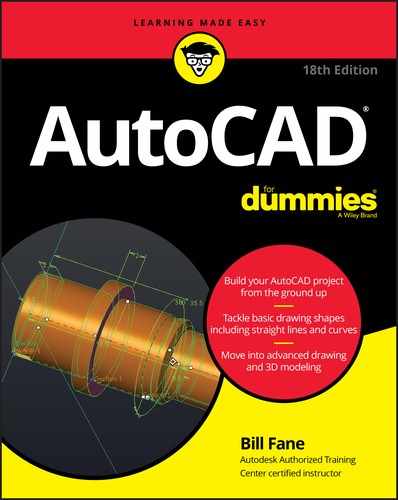
If you assign properties with the ByLayer approach, all you have to do is set layer properties in the Layer Properties Manager palette, as shown in Figure 9-1. (I tell you how in this section.) Before you draw any objects, verify that the Color Control, Linetype Control, and Lineweight Control drop-down lists — and the Transparency button in the Properties panel on the Home tab of the Ribbon — are all set to ByLayer, as shown in Figure 9-2. Remember that the configuration of panels and drop-down lists may vary according to the resolution of the display. If the drawing is set to use color-based plot styles rather than named plot styles, as described in Chapter 16, the Plot Style Control drop-down list is inactive and displays ByColor.
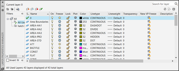
FIGURE 9-1: Use layer properties to control object properties.

FIGURE 9-2: ByLayer (nearly) all the way.
If the drawing is set to use named plot styles rather than color-based plot styles (see Chapter 16), the Plot Style control drop-down list should also display ByLayer.
 Don’t assign properties to objects in either of these ways:
- Don’t choose a specific color, linetype, lineweight, transparency, or plot style from the appropriate drop-down list in the Properties panel on the Home tab of the Ribbon, or from the Properties palette, and then draw the objects. All new objects will be on the current layer but will have property overrides applied.
- Don’t draw the objects, select them, and then choose a property from the same drop-down lists.
If you prefer to do things the right way (that is, my way), assign these properties ByLayer, as described in the later section “Working with Layers.”
 If you want to become a good CAD manager, learn how to edit the Customizable User Interface (CUI) file in AutoCAD, and then delete the property override items from the Ribbon.
The SETBYLAYER command in AutoCAD lets you correct non-ByLayer properties. On the Home tab of the Ribbon, click the Modify panel label to open the panel slideout, and then click Set to ByLayer. Answer the prompts at the command line to finish modifying objects. For more information, refer to SETBYLAYER in the online Help system.
Changing properties
![]()
![]() You can view and change all properties of an object in the Properties palette (its icon is shown in the margin), and many of them in the Quick Properties palette (the second icon in the margin). In Figure 9-3, the Properties palette at the left and the Quick Properties palette at the right show properties for the selected line object. Launch the Properties palette by clicking the diagonal down arrow in the lower-right corner of the Properties panel of the Home tab.
You can view and change all properties of an object in the Properties palette (its icon is shown in the margin), and many of them in the Quick Properties palette (the second icon in the margin). In Figure 9-3, the Properties palette at the left and the Quick Properties palette at the right show properties for the selected line object. Launch the Properties palette by clicking the diagonal down arrow in the lower-right corner of the Properties panel of the Home tab.
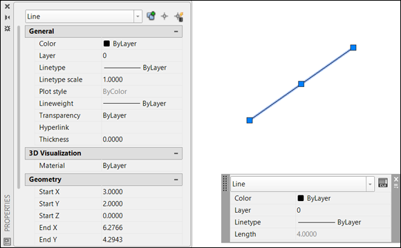
FIGURE 9-3: Comprehensive or quick? Sometimes you need lots of information, and sometimes you don’t.
The Properties palette was joined in AutoCAD 2009 by its more streamlined little sibling, Quick Properties (QP). When you turn on the QP palette on the status bar, selecting an object opens a floating palette that displays a customizable selection of that object’s properties.
Handy as it is, the Quick Properties palette has a knack of popping up on top of drawing objects that you need to see. In AutoCAD, you can let Quick Properties mode remain turned off at the status bar and instead use the QuickProperties command. Type its alias (QP) and then select an object to display the Quick Properties panel. You can also double-click most objects to display their quick properties.
To toggle the full Properties palette on and off, click the Properties button on the View tab of the Ribbon or press Ctrl+1. Before you select an object, the Properties palette displays the current properties — properties that AutoCAD applies to new objects when you draw them. After you select an object, the Properties palette displays the properties for that object. If you select more than one type of object, the Properties palette displays, and then changes the properties that they have in common.
Properties and Quick Properties let you change any properties of one or more selected objects. You should change the main properties (such as color, linetype, and lineweight) only by moving the objects to a different layer.
If you’re a CAD manager, you can easily customize the Quick Properties palettes to remove undesirable properties. For detailed instructions, search for customize quick palettes in the Help search window.
Working with Layers
Every object has a layer as one of its properties. Conceptually, layers had their origins in complex paper-and-pencil architectural drawings. After laying out the basic foundation plan on a sheet of paper, the architect placed a sheet of clear plastic on top and drew the walls. This process was repeated with separate sheets for tasks such as plumbing, electrical, and ventilation. When all layers of plastic were in place, the architect could check for interferences to prevent a ventilation duct from running directly through a major support column, for example. When everything checks out, the architect could produce suitable blueprints for the plumber and other interested parties by simply removing layers that weren’t appropriate. An electrician doesn’t need to know where the pipes run, for example.
AutoCAD, like most CAD programs, uses the layer as the primary organizing principle for all objects you draw. You use layers to organize objects into logical groups of items. For example, walls, furniture, dimensions, and text notes usually belong on four separate layers, for a couple of reasons:
- Layers give you a way to turn groups of objects on and off, both on the screen and on the plot.
- Layers provide the most efficient way of changing object color, linetype, lineweight, transparency, and plot style.
So, to work in AutoCAD efficiently, you create as many layers as the drawing needs and assign them suitable names and properties, such as colors and linetypes. Then you draw objects on specific layers. When you draw an object, AutoCAD automatically puts it on the current layer — the layer you see in the Layer drop-down list on the Layers panel of the Home tab when no objects are selected. You can also set things up so that dimensions and hatching automatically get put on specific layers. I cover this in Chapters 13 and 14. If a layer already exists in the drawing, you can make it the current layer by choosing it from the Layer drop-down list, as shown in Figure 9-4.
FIGURE 9-4: Setting an existing layer as the current layer.
You don’t have to create all layers before drawing an object, but it saves you some time if you start as many layers as you estimate you need and then add more layers only as needed. You can save even more time by creating all the layers you need in a new drawing and then saving it as a template file (covered in Chapter 4). Now each drawing you start from that template has all the layers you need. In fact, most companies have (or should have) a standard template file already set up to their layer standards. Similarly, outside clients probably have standard layer sets.
No objects can be selected before you use the Layer drop-down list to change the current layer, so press the Esc key twice to be certain. If objects are selected, selecting another layer from the Layer drop-down list changes their layers. When no objects are selected, the Layer drop-down list displays (and lets you change) only the current layer.
Accumulating properties
Besides layers, the remaining object properties that you’re likely to want to use often are color, linetype, lineweight, transparency, and possibly plot style. Table 9-1 summarizes the properties you use most often.
TABLE 9-1 Useful Object Properties
|
Property |
What It Controls |
|
Color |
Displayed colors and plotted lineweights or colors |
|
Linetype |
Displayed and plotted dash-dot line patterns |
|
Lineweight |
Displayed and plotted line widths |
|
Transparency |
Displayed and plotted opacity of objects |
|
Plot style |
Plotted characteristics (see Chapter 16) |
Long before AutoCAD could display lineweights on the screen and print those same lineweights on paper, object colors controlled the printed lineweight of objects. Color identified different objects, such as part outlines, hidden lines, center lines, and cutting plane lines. When the time came to plot the drawing using (now mostly defunct) pen plotters, AutoCAD sent all red objects to pen 1, yellow to pen 2, green to 3, and so on.
Although pen plotters could plot in color, most companies installed pens that used black ink but had different pen widths. For example, the color red in a drawing told the plotter to use pen 1 that was black and might have had a width of 0.12mm. The color green plotted using pen 3 that was black and might have had a width of 0.20mm. This was done for each color that was used in a drawing, which were commonly not more than 8 because a pen plotter typically did not hold more than eight pens.
AutoCAD 2000 introduced a more logical system, by which you could assign an actual plotted lineweight to an object. As logical as this method seems, the older method — in which the color of an object determines its plotted lineweight — continues to dominate, perhaps in part because of the ready availability of color printers. You may work this way even in AutoCAD 2020, for compatibility with drawings (and coworkers) that use the old way. Figure 9-5 shows you the idea. The model space view at the left shows objects in different colors but with the same default lineweight. The paper space view at the right (showing what the plotted drawing will look like) shows that although the lines are black, their thicknesses vary, determined by the model space colors. For example, blue is thick, and black is thin.
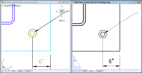
FIGURE 9-5: Change my line thickness, but color me black.
Creating new layers
If no suitable layer exists, you create one in the Layer Properties Manager palette. Follow these steps:
-
 Click the Layer Properties button in the Layers panel on the Home tab of the Ribbon, or type LA at the command line and then press Enter.
The Layer Properties Manager palette appears. A new drawing has only one layer: Layer 0 (zero). You need to add the layers necessary for the drawing.
The Layer Properties Manager palette, as well as individual columns within it, can be stretched wider so as to not truncate information. The easy way is to right-click a column header and then choose Maximize All Columns. -
Click the New Layer button (it looks like a sheet of paper with a little sunburst on one corner) to create a new layer.
A new layer appears. AutoCAD names it Layer1 but highlights the name in an edit box so that you can type a new name to replace it easily, as shown in Figure 9-6.
-
Type a name for the new layer.
Type a layer name using initial caps — only the first letter of each word is in uppercase. Because layer names written in all uppercase letters are much wider than others, they’re often truncated (abbreviated) in the Layer drop-down list. Layer names should be descriptive and organized so that they’re easily identifiable and can be sorted logically. For example, names such as Floor 01 Plan, Floor 01 Walls, Floor 01 Electrical, and Floor 02 Plan are better than a drawing I saw recently that had 132 layers named with the sequence 001, 002, 003, 004, and so on. As of 2014, AutoCAD sorts in natural order: Old Way
New Way
Floor 1 Walls
Floor 1 Walls
Floor 10 Walls
Floor 2 Walls
Floor 2 Walls
Floor 10 Walls
-
On the same line as the new layer, click the color block or color name (by default, the same as the current layer) of the new layer.
The Select Color dialog box appears, as shown in Figure 9-7, with Magenta selected from the Color Index list.
The normal AutoCAD color scheme, known as the AutoCAD Color Index (ACI), provides 255 colors. That number of choices is overkill for ordinary drafting, but if you truly want to go overboard, the True Color tab provides more than 16 million colors, whereas the Color Books tab gives access to many standard color books such as Pantone books, which are used by the design and printing industries.
For now, stick with the first nine colors — the ones that appear in a single, separate row to the left of the ByLayer and ByBlock buttons on the Index Color tab in the Select Color dialog box — for these reasons: - These colors are easy to distinguish from one another.
- Using a small number of colors makes configuring plot parameters easier. (I describe plot parameters in Chapter 16.)
-
Click a color to select it as the color of this layer and then click OK.
The Select Color dialog box closes. In the Layer Properties Manager palette, the Color column now has the new layer color — either the name or the number of the color you selected.
 The first seven AutoCAD colors have numbers, standard names, and initials: 1 = Red, 2 = Yellow, 3 = Green, 4 = Cyan, 5 = Blue, 6 = Magenta, and 7 = White (which appears black when displayed on a white background). The remaining 248 colors have numbers only.
 -
On the same line as the new layer, click the Linetype name of the new layer to draw a dashed (hidden) line.
The Select Linetype dialog box appears, as shown in Figure 9-8.
The default AutoCAD linetype is Continuous — the line has no gaps.
If you already loaded the linetypes you need for the drawing, or if the initial template file has linetypes loaded, the Select Linetype dialog box displays them in the Loaded Linetypes list. If not, click the Load button to open the Load or Reload Linetypes dialog box. By default, AutoCAD displays linetypes from the standard AutoCAD or AutoCAD LT linetype definition file —
acad.linfor imperial-unit drawings oracadiso.linfor metric-unit drawings (acadlt.linandacadltiso.linin AutoCAD LT). Load a linetype by selecting its name and clicking OK. Unless you have a truly good reason (for example, your boss tells you so), avoid loading or using any linetypes labeled ACAD_ISO. These linetypes are normally used only in metric drawings based on standards from ISO (International Organization of Standards) — and rarely even then. It’s easier to use the linetypes with the more descriptive names: CENTER and DASHED, for example. -
Click a linetype in the Loaded Linetypes list to select it as the linetype for the layer; then click OK.
The Select Linetype dialog box disappears, returning you to the Layer Properties Manager palette. In the Name list, the linetype for the selected layer changes to the linetype you just chose.
-
On the same line as the new layer, click the new layer’s lineweight.
The Lineweight dialog box appears, as shown in Figure 9-9.
-
Select the lineweight you want from the list and click OK.
 Using the lineweight property is a two-step process. After you assign a lineweight to a layer, you must click the Show/Hide Lineweight button on the status bar to see the effect. You can turn the feature off and on with this button. A lineweight of 0.00mm tells AutoCAD to use the thinnest possible lineweight on the screen and on the plot. I recommend, for now, leaving the lineweight set to Default, and instead later map screen colors to plotted lineweights, as described in greater detail in Chapter 16.
 -
(Optional) In the same line as the new layer, click the value in the Transparency column.
You’ll appreciate AutoCAD’s transparency property if you’re preparing drawings for a presentation. Clicking in the Transparency column opens the Layer Transparency dialog box; type a numeric value between 0 and 90 or use the drop-down list to set a value. Transparency = 0 (no transparency) is the default; objects drawn on a layer set to Transparency = 0 are opaque.
Set the value to greater than 0, and you start seeing things through the objects you draw.
-
(Optional) Set the plot style for the new layer.
The Plot Style column’s contents depend on whether the drawing uses named plot styles or the traditional color-based plotting. Drawings set up to use color-based plotting display an unchangeable plot style name based on the layer’s color property. The grayed-out style name changes only when the layer color changes. If, on the other hand, the drawing uses named plot styles, you can assign a named plot style to the layer in this column. (Chapter 16 explains why you might not want to.)
-
(Optional) Turn plotting on and off.
The setting in the Plot column controls whether the layer’s objects appear on plots. Click the little Printer icon to turn off this setting (the little printer gets a red bar through it) for any layer whose objects you want to see on the screen but hide on plots. Layout viewports, covered in Chapter 12, are a good use for this feature.
Another use for this feature is antagonizing coworkers. Go into one of their drawings, start the Layer Properties Manager, and turn off plotting on a few random layers. Now go to the top of the Plot column, click the divider between it and the adjacent column, and reduce the Plot column’s width to nearly zero. Even a senior experienced AutoCAD user can go nuts trying to figure out why some layers won’t plot.
-
(Optional) To add a description to the layer, scroll the layer list to the right to see the Description column, click in the Description box corresponding to the new layer, and type a description.
If you use layer descriptions, stretch the Layer Properties Manager palette to the right so that you can see the descriptions without having to scroll the layer list. - Repeat Steps 1–13 to create any other layers you want.
-
Select the new layer that you want to make current, and click the Set Current button (the green check mark).
Changes you make in the Layer Properties Manager palette are instantaneous. Therefore, if objects in the drawing are already on a particular layer and you change the color for that layer, the existing drawing objects change color immediately and don’t wait for you to close the palette.
The Layer drop-down list now displays the new layer as the current layer — the one on which AutoCAD places new objects you draw.
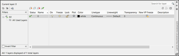
FIGURE 9-6: Adding a new layer in the Layer Properties Manager palette.
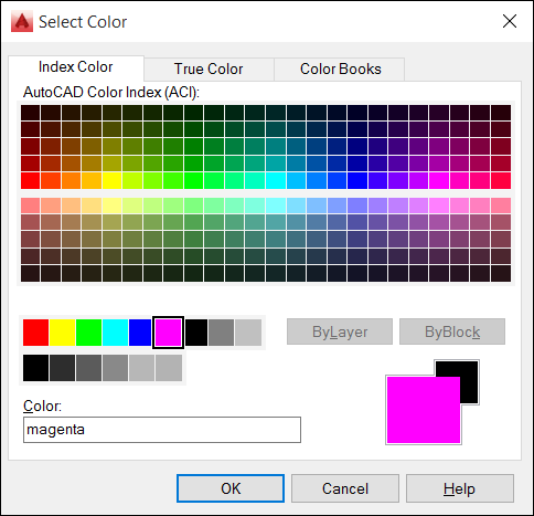
FIGURE 9-7: The Select Color dialog box.
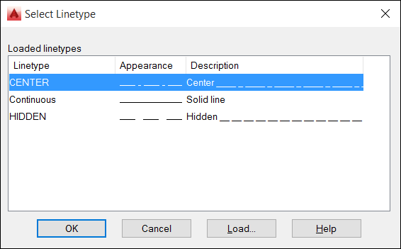
FIGURE 9-8: The Select Linetype dialog box.
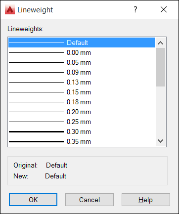
FIGURE 9-9: The Lineweight dialog box.
As with all palettes in AutoCAD, you can leave the Layer Properties Manager open while you do other things in the drawing. Also like other palettes, the Layer Properties Manager can be set to automatically hide itself to its title bar, to be either floating or docked, or to be anchored (I get the sense that some AutoCAD programmers would rather be sailing) to either side of the screen. If your computer has two monitors, you can drag the palettes to the second monitor.
Layer 0 (zero) must exist in every drawing. You can assign any of the other properties to it such as color and line type, but you cannot rename it.
Set up layers in a template file and then you almost never need the Layer Properties Manager while you’re working.
Here are a few things you can do to work effectively with layers:
- Set a layer to be the current layer. Make sure that no objects are selected, and then choose the layer name from the Layer drop-down list on the Layers panel on the Ribbon or the Layers toolbar.
- Toggle properties on and off. You have to turn on the Transparency button on the status bar to see through objects. You can also toggle the Lineweight and Transparency buttons on the status bar to see the effect of assigning these properties.
-
Adjust the lineweight properties and scale. When you finish defining layers and return to the command line, the Lineweight dialog box lets you adjust several lineweight properties, including inches-versus-millimeters and the display scale.
The display scale affects only how elements appear onscreen, not how they’re plotted.
- Let the command line find layers for you. The command line automatically completes layer names, among other named objects, and it searches for matching partial text within layer names. Follow these steps:
- Open a drawing that contains layers. If you created the base plate in Chapter 3, open that.
- Make sure that Dynamic Input (F12) is turned off. Unfortunately, this functionality works only when DYNamic Input is off.
- Start typing letters in the layer name you’re looking for, but don’t press Enter. If you’re using the base plate, you type BO. Figure 9-10 shows how the command line displays the three command names that start with BO — plus, it shows
Layer: Anchor Boltsbecause it found theBoin Bolts. - Click the layer name. It becomes the current layer.

FIGURE 9-10: Type, and the command line shall find.
Manipulating layers
After you create layers and draw objects on them, you can turn a layer off or on to hide or show the objects on that layer. In the Layer Properties Manager palette, the first three icons to the right of the layer name control AutoCAD’s layer visibility modes:
- Off/On: Click the lightbulb icon to toggle visibility of all objects on the selected layer. AutoCAD doesn't regenerate the drawing when you turn layers back on. On the other hand, frozen layers don’t regenerate while you're working on the drawing. I give you the lowdown on regeneration in Chapter 5. Current computers are usually fast enough that regens aren’t a problem, so Off/On is seldom used.
- Freeze/Thaw: Click the sun icon to toggle off visibility of all objects on the selected layer. Click the snowflake icon to toggle visibility on. AutoCAD regenerates the drawing when you thaw layers.
- Lock/Unlock: Click the padlock icon to lock and unlock layers. When a layer is locked, you can see (but not edit) objects on that layer.
You can rearrange the column order within the Layer Properties Manager by simply dragging and dropping the column label to a new place. And you can right-click any column label to display a menu from which you can turn columns off and on.
Off/On and Freeze/Thaw do almost the same thing — both settings let you make objects visible or invisible by layer. Very early releases had only Off/On. The difference is that frozen layers effectively don’t exist temporarily, so AutoCAD ignores them when regenerating the drawing.
Normally, it’s faster and easier to turn layers off and on, freeze and thaw them, and lock and unlock them by clicking the appropriate icons in the Layer drop-down list on the Ribbon instead of using the Layer Properties Manager palette.
Here are a few other useful tricks you can try when working with layers:
- Create layer states. Say you have a floor plan of a house that includes a layer showing the plumbing and another layer showing the wiring. You’d probably never show both elements on the same drawing, so you’d need to manage some layers to show the drawing to plumbers or electricians. Rather than turn off a dozen layers and turn on another dozen layers when you want a different view in the drawing, you can save groups of layer settings as a named layer state. Click the Layer States Manager button in the Layer Properties Manager to open the Layer States Manager dialog box, or enter LAYERSTATES at the command line, or choose Manage Layer States from the Layer State drop-down list in the Layers panel.
-
Fade objects on locked layers. AutoCAD fades objects on locked layers, giving you a truly effective visual reference without confusing you about which layers might be locked. You can control the amount of fading by setting a nonzero value for the system variable LAYLOCKFADECTL. See Chapter 26 for an explanation of system variables, and check out the online Help system for specific info on this one. You can turn off fading but retain the current setting for future use by adding a minus sign (–) in front of the fade value, or you can turn off the fading altogether by setting this value to 0.
The LAYISO (LAYer ISOlate) command incorporates the same layer-fading feature, and it locks the layers. Set it up the way you want by entering S (for Settings) at the command line and pressing Enter; and then type the option letter for the specific settings you want. Look up LAYISO in the online Help index for more information.
-
Create a layer filter. If you find that you’re using lots of layers, you can create layer filters to make viewing and managing the layer list easier:
- A group filter is a subset of layers you choose (by dragging layer names into the group filter name or by selecting objects in the drawing).
- A property filter is a subset of layers that AutoCAD creates and updates automatically according to layer property criteria that you define (for example, all layers whose names contain Wall or whose color is green).
To find out more, press F1 in the Layers Properties Manager palette, and click the New Property Filter hyperlink.
-
Isolate a layer. On the Layers panel of the Home tab of the Ribbon (shown in Figure 9-11), click the Layer Isolate and Layer Off button to specify the layer to isolate (that is, fade all layers except the chosen one) or turn off altogether. You may have to open the panel slideout to see these buttons.
For more information on layers, open the online Help system and search on controlling layers manager.
- Hide or isolate objects on a layer. Rather than turn off a layer when only a few items are in the way, you can hide or isolate individual objects by using the ISOLATEobjects and HIDEOBJECTS commands while maintaining normal visibility for other objects on the layer. I discuss these commands in Chapter 10.

FIGURE 9-11: Tooling through the layer tools.
Scaling an object’s linetype
Linetype scale controls the display of dash-dot linetypes in a drawing. Some linetypes that you assign to a layer or an object directly might not look correct on every object based on the drawing’s current linetype scale. The problem with the linetypes is that the dashes and gaps are not always noticeable on every object because of the object’s size or the way the object was drawn.
To fix this problem, you can change the object’s linetype scale that is normally set to a value of 1. The object’s linetype scale is used as a multiplier with the drawing’s linetype scale factor. For example, if you change an object’s linetype scale factor to 1.5 and the drawing’s linetype scale factor is 12, the linetype applied to the object is actually displayed with a linetype scale of 16 (1.5 x 12).
Follow these steps to scale the object’s lineweights:
- Start a new drawing by using the standard
acad.dwtoracadlt.dwttemplate. -
Create a layer that uses the Hidden linetype and set this layer to be current.
If you don’t feel like creating a new layer, you can always simply set the linetype for Layer 0 (zero) to hidden.
- Set the limits to be from 0,0 to 100,100.
- Enter Zoom and press Enter. Then enter A and press Enter to zoom to the limits you set.
-
Start the Line command, and type coordinates to draw a line from 10,10 to 70,70.
Hey, what happened? That doesn’t look like a hidden line! Well, it is, even if it doesn’t look like one. The problem is that the line is so long and you’ve zoomed out so far that the individual spaces and dashes are too small and have all merged into one. The bigger problem is that if you were to plot this drawing to fit an A-size (8½ x 11) sheet of paper, the line would look just as it does onscreen.
-
 Click the Annotation Scale button in the status bar and select 1:20/5% from the drop list, and then REgenerate the drawing.
Ah, that’s better! As I mention in Chapter 4, you need to apply a plotting scale of 1:20 to fit the line on the paper, but then everything scales down, including the spaces and dashes in noncontinuous lines. The Annotation Scale setting with a value of 1:20 tells AutoCAD to make the dashes and spaces 20 times longer so that they scale down properly on the screen and when you plot. I cover this topic in more detail in Chapters 13–15.
-
Start the Line command, and type coordinates to draw a line from 30,10 to 100,80.
The new line should look just like the first line you drew.
Using Named Objects
One thing that can make AutoCAD interesting is the somewhat cavalier naming conventions used in the program’s documentation. For years, elements such as lines, arcs, and other graphical items were called entities, but then they started being called objects. Fair enough, but object has also long been used to define certain nongraphical components of a drawing — items you’d hardly even consider to be objects — and those are the kind of named objects I describe in this section.
Hidden in the innards of every AutoCAD drawing file is a set of named objects, which are organized into symbol tables, and the properties that are common to all AutoCAD objects are defined in these tables. For example, all line objects in a drawing are stored on one or more layers, so a layer property is common to all lines and is defined in the layer table. But the coordinates that define the start and end points of a given line are unique to that line (or they should be!), so the coordinate properties aren’t common to all lines.
A layer is one example of a named object. The layer table in a given drawing contains a list of the layers in the current drawing, along with the settings for each layer including the color, linetype, and on/off setting.
Named objects don’t appear as graphical objects in the drawing. They’re like the hardworking behind-the-scenes pit crews who keep race cars running smoothly. These named objects are the ones you’re likely to use most often (including cross-references):
- Layer: They’re covered in the section “Working with Layers,” earlier in this chapter.
- Linetype: They’re covered in the section “Working with Layers,” earlier in this chapter.
- Text style: See Chapter 13.
- Table style: See Chapter 13.
- Multileader style: See Chapter 13.
- Multiline style: This object isn’t covered in this book; see the online Help system.
- Dimension style: See Chapter 14.
- Block definition and xref: See Chapters 17 and 18.
- Layout: See Chapter 12.
When you use commands such as LAyer, LineType, and DimSTyle, you’re creating and editing named objects. After you create named objects in a drawing, the AutoCAD DesignCenter or Content Explorer give you the tools to copy them between drawings.
A major real-estate developer might believe otherwise, but you can have too many properties (at least in AutoCAD). You may have created layers or loaded linetypes, text, or dimension styles that you don’t use. When you suspect that you have some of these superfluously named objects in the drawing, the PUrge command can help you get rid of them. Click the application button to display the Application menu. Choose Drawing Utilities ⇒ Purge to open the Purge dialog box. You can click the plus sign (+) beside a category to purge individual items, or you can click Purge All and get rid of tons of stuff all at one time. Visit the online Help system for more about purging.
Using AutoCAD DesignCenter
DesignCenter is a useful, if somewhat busy, palette. It is launched from the Palettes panel of the View tab. The DesignCenter palette is handy for copying the specifications of named objects: layers, linetypes, block definitions, text styles, and other organizational objects in drawings from one drawing to another.
The DesignCenter palette, shown in Figure 9-12, consists of a toolbar at the top, a set of three tabs below that, a tree view pane on the left, and a content pane on the right. The tree view pane displays a Windows Explorer–like navigation panel, showing drawing files and the symbol tables contained in each drawing. The content pane usually displays the contents of the selected drawing or symbol table.

FIGURE 9-12: The AutoCAD DesignCenter palette.
The three tabs just below the DesignCenter toolbar control the elements you see in the tree view and content panes:
- Folders: Shows the folders on the local and network drives, just as the Windows Explorer Folders pane does. Use this tab if the drawing you want to copy from isn’t open now in AutoCAD.
- Open Drawings: Shows the drawings that are open in AutoCAD. Use this tab (it’s current in Figure 9-12) to copy named objects between open drawings.
- History: Shows drawings that you’ve recently browsed in DesignCenter. Use this tab to jump quickly to drawings that you’ve used recently on the Folders tab.
The toolbar buttons further refine what you see in the tree view and content panes. A few of these buttons toggle different parts of the panes.
A detailed description is beyond the scope of this book, but the bottom line is that you can drag and drop the specifications of named objects from one drawing into another. This can be handy at times, but it must be used with care. In particular, if your company or client has defined standards, they should be set up in a template file (see Chapter 4). A danger of copying from an existing drawing is that the standards may have been revised over time, and you might not be copying from the latest version.