Chapter 5
A Zoom with a View
IN THIS CHAPTER
![]() Zooming and panning
Zooming and panning
![]() Naming and restoring views
Naming and restoring views
![]() Zooming and panning in paper space layouts
Zooming and panning in paper space layouts
![]() Regenerating the display
Regenerating the display
One advantage that AutoCAD has over manual drafting is its ability to show you different views of a drawing.
You move the viewpoint in, or zoom in, to see a closer view of the objects in a drawing; you move the viewpoint out, or zoom out, to see a more expansive (not expensive) view. If you watch TV or movies or own a camera, you should understand zooming.
Panning doesn’t refer to looking for gold but rather, looking at a different part of a drawing without changing the magnification of the view. If you zoom in so that part of the drawing is no longer shown onscreen, you’ll pan around in the drawing without zooming in and out. Think of the monitor as a window through which you’re looking at part of the drawing. Now reach through the window and slide the drawing around until you can see a different portion of it through the window.
 Panning and zooming do not change the size or position of objects within the drawing. They change only how you see them.
In fact, you not only can zoom and pan in the drawing but also, in most kinds of drawings, you must zoom and pan frequently to be able to draw and edit effectively.
Why do you need to pan and zoom often? For starters, though many architectural drawings plot out at 3 feet by 2 feet, you probably aren’t fortunate enough to own a monitor of that size with sufficient resolution to be able to see every little detail.
In addition, technical drawings are jam-packed with lines, text, and dimensions. As discussed in Chapter 8, drawing with precision is essential to following best practices for AutoCAD drawings. Frequent zooming and panning enables you to better see detail, to draw more precisely because you can see what you’re doing, and to edit more quickly because object selection is easier when the screen isn’t cluttered with objects. This chapter describes the most useful display control features in AutoCAD.
Zooming and Panning with Glass and Hand
AutoCAD makes panning easy, by offering scroll bars and real-time panning. In real-time panning (as opposed to pretend-time panning?), you can see objects moving on the screen as you drag the mouse upward and downward or back and forth. Of course, the viewpoint is moving, not the objects.
Both panning and zooming change the view — the current location and magnification of the AutoCAD depiction of the drawing. Every time you zoom or pan, you establish a new view. You can name a specific view so that returning to it is easy, as I demonstrate in the later section “A View by Any Other Name.”
You can gain a better sense of panning and zooming in a drawing when you’re looking at a drawing. Draw some objects on the screen, open an existing drawing, or launch a sample drawing in AutoCAD.
If you haven’t done so already, you can download sample files from www.autodesk.com/autocad-samples. (You can ignore the version numbers.) The AutoCAD LT sample files are also online at www.autodesk.com/autocadlt-samples. Note that LT drawings can be opened by standard AutoCAD and vice versa.
The wheel deal
Later in this chapter, I cover in detail various commands and options in AutoCAD for panning and zooming — if you have a wheel mouse, however, you’ll rarely need to use other methods, especially when working in 2D drawings. If you don’t have a wheel mouse, run out and buy one now because the slight cost will be more than offset by your increased productivity. The following three actions usually suffice for almost all panning and zooming needs:
- Zoom in, zoom out: Roll the scroll wheel forward and backward.
- Pan: Hold down the scroll wheel as you move the mouse. (The scroll wheel is also considered a button.)
- Zoom to the extents of a drawing: Double-click the scroll wheel. This method is particularly useful when you accidentally press Enter at the wrong time during a Move or Copy operation, as described in Chapter 11.
 Using the scroll wheel (or middle button on a mouse that has three buttons) for zoom and pan operations depends on the setting of the obscure AutoCAD system variable named MBUTTONPAN. When MBUTTONPAN is set to the default value of 1, you can use the scroll wheel or middle button to pan and zoom. Unless the system has been customized, if you change MBUTTONPAN to 0, clicking the scroll wheel or middle mouse button displays the Object Snap menu at the cursor, as it did in earlier AutoCAD releases. If you can’t zoom or pan using the scroll wheel or middle mouse button, set MBUTTONPAN to 1. When MBUTTONPAN is set to 1 you can press Shift+right-click to display the Object Snap menu at the cursor. I discuss Object Snaps in Chapter 8.
Navigating a drawing
You may believe that AutoCAD is all about drawing and, occasionally, even about erasing. If so, you may be surprised to read that two of the most frequently used commands in all of AutoCAD are Pan and Zoom although the hands-down favorite is Undo. You can find these two commands in a couple of convenient places in AutoCAD:
- On the Navigation bar: The Navigation bar contains both Zoom and Pan buttons. Figure 5-1 shows the upper-right corner of the AutoCAD window with the Navigation bar in its default location, linked to the ViewCube. Because the ViewCube is more useful in 3D drawing, I tell you about it in Chapter 21.
-
In the Navigate and Navigate 2D panels on the View tab on the Ribbon: These two panels contain a Pan button and a drop-down set of Zoom tool buttons. This location is not the most convenient for frequently used commands — and to make matters worse, this panel may not even be visible. To display it you must right-click anywhere in the View tab, click Show Panels, and then click Navigate.
If you’re primarily creating 2D drawings, you can remove some of the 3D related viewing tools from the Navigation bar or turn off the ViewCube itself, either for the drawing session or permanently. Choose a method:
- Turn off navigation buttons. Open the Navigation bar menu by clicking the down arrow in its lower-right corner (refer to Figure 5-1) and deselect SteeringWheels, Orbit, and ShowMotion.
- Turn off the ViewCube or the Navigation bar (or both) in the current viewport. From the User Interface panel on the View tab, click User Interface and deselect ViewCube or Navigation bar or both.
- Turn off the ViewCube permanently. Open the Options dialog box (choose Options from the Application menu or type OPtions) and select the 3D Modeling tab. In the Display Tools in Viewport section, under the Display the ViewCube line, deselect the two options 2D Wireframe Visual Style and All Other Visual Styles.
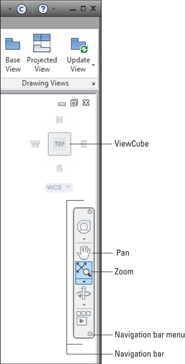
FIGURE 5-1: Belly up to the Navigation bar.
 In AutoCAD, unlike in most other Windows programs, panning and zooming are usually more convenient and faster than scrolling. If you want the traditional Windows scroll bars on the right and bottom borders of the drawing window to scroll, you can turn them on. Choose Options from the Application menu (or type OPtions) to display the Options dialog box. On the Display tab, select or deselect the Display Scroll Bars in Drawing Window check box. The default, and most users’ preference, is not to use scroll bars, thereby regaining the screen space they occupy. That’s why you don’t see them in most figures in this book.
Zoom, Zoom, Zoom
Because zooming is a frequent activity in AutoCAD, you should know some alternative ways to zoom.
In addition to the Zoom button on the Navigation bar I describe earlier in this chapter, you’ll find tool buttons for all the Zoom options in the Navigate panel on the View tab.
As mentioned earlier, the Navigate panel on the View tab is turned off by default.
Click the small down arrow in the lower-right corner of the panel and a menu with the other options opens, as shown in Figure 5-2.
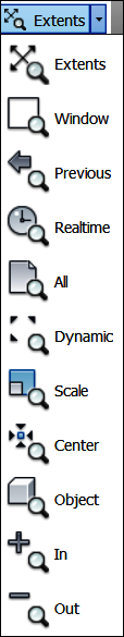
FIGURE 5-2: A menu for magnifying.
The Zoom command has 11 options. The most important ones are described in this list:
-

 Extents and All: The Zoom Extents button (with the four-headed arrow and the magnifying glass) zooms out just far enough to show all objects in the current drawing. The Zoom All button (showing the sheet with the folded-over corner) does almost the same thing: It zooms to show the rectangular area defined by the drawing limits set with the LIMITS command, or it zooms to show the extents — whichever is larger. These two options are especially useful when you zoom in too close or pan off into empty space and want to see the entire drawing again. Limits and extents are slightly different. Limits are set by the Limits command. You can configure AutoCAD to not allow you to draw anything outside the limits, but this usually causes more problems than it solves. Extents are defined by the smallest imaginary rectangle that will just surround every object in your drawing. A good April Fool’s trick is to sneak up to another person’s computer and draw a tiny circle by typing the location coordinates as something like 10000,10000. The next time the person does a Zoom Extents, his or her drawing will seem to disappear. Use Zoom All or Zoom Extents and then save the drawing before you close it to ensure that:
 - The next person who opens the drawing can see the full drawing as soon as he or she starts working.
- Any objects that you accidentally copied beyond the drawing limits show up so that you can delete or move them.
- The drawing preview that appears in the Select File dialog box and on the Start screen displays the full drawing rather than a tiny, unidentifiable corner of it.
-
 Window: This option, which is useful for zooming in quickly and precisely, zooms to a section of the drawing that you specify by clicking two points. The two points define the diagonal of a window around the area you want to see. The Zoom command’s Window option is not a click-and-drag operation, unlike in most other Windows programs and — confusingly — unlike in the Zoom/Pan Realtime Zoom Window option. To use the Zoom command’s Window option, you click one corner, release the mouse button, and then click the other corner.
  Realtime: Enables you to zoom in and out by starting a real-time zoom and then dragging the magnifying-glass cursor up (to zoom in) or down (to zoom out).
 Previous: Use this option to undo the last zoom or pan sequence (or both), returning to where you started. You can repeat this option to step through previous views, even if you create or edit objects after changing the view.
 Object: This option zooms in close enough to show selected objects as large as they can be displayed onscreen. Using Zoom Object is similar to examining selected objects under the AutoCAD microscope.
Entering the keyboard command sequences Z A, Z P, or Z W (note the mandatory space between the letters) is usually faster than trying to find the corresponding zoom tools on the Ribbon or various toolbars. Z is the command alias for the Zoom command, while A, P, and W start the All, Previous, and Window options, respectively. These three command sequences, in combination with the wheel mouse, typically account for more than 99 percent of your panning and zooming needs. (I almost never use any Ribbon or navigation bar options.)
I cover another important Zoom option when discussing paper space viewports in Chapter 12.
A View by Any Other Name
If you repeatedly have to zoom and pan to the same area, you can quickly see what you want to see by using a named view. After you name and save a view of a particular area of a drawing, you can return to that area quickly by restoring the view. You use the View command, which displays the View Manager dialog box, to create and restore named views.
Follow these steps to create a named view:
- Zoom and Pan until you find the area of the drawing to which you want to assign a name.
-
Start the View command from the keyboard. Or on the View tab on the Ribbon, click View Manager in the Views panel.
If the Views panel is not visible, right-click anywhere in the View tab, click Show Panels, and then click Views.
The View Manager dialog box opens.
-
Click New.
The New View/Shot Properties (New View in AutoCAD LT) dialog box appears, as shown in Figure 5-3.
- Type a name in the View Name text box.
-
(Optional) Type a new category in the View Category text box, or select an existing one from the drop-down list.
You create your own view categories to organize views and certain display characteristics of views. This feature is used mainly in sheet sets. If you aren’t using them, you can leave the default value, <None>, in the View Category box or clear the current value. (A discussion of sheet sets is beyond the scope of this book.)
-
Make sure that the View Type drop-down list is set to Still.
The Still option creates a static thumbnail image of the objects in the area that is defined by the named view for use in ShowMotion. Visit the online Help system if you want to know more about the Cinematic and Recorded Walk options that you can choose from this drop-down menu, which are used mainly in 3D work.
AutoCAD LT doesn’t support view types, so if you’re working with AutoCAD LT, skip Step 6. The New View dialog box in AutoCAD LT omits the View Type list box, most of the Settings drop-down options, and the Background area.
-
In the Boundary area, select the Current Display radio button, if it isn’t selected already.
If you want to save a different view boundary, select the Define Window radio button instead, click the Define View Window button that appears to the right of it, and pick two corners of the region’s boundary (as though you’re zooming windows). -
If you really want to get fancy, click the down arrow in the lower-left corner.
A detailed description of all the options is beyond the scope of this book.
-
Confirm or change the choices.
If you select the Save Layer Snapshot with View check box, when you later restore the view, AutoCAD also restores the layer visibility settings (On/Off and Freeze/Thaw) that were in effect when you created the view. I discuss layer visibility settings in Chapter 9. The Live Section and Visual Style settings are intended primarily for 3D drawings; these two settings aren't included in AutoCAD LT.
-
Click OK.
The New View/Shot Properties (New View in AutoCAD LT) dialog box closes, and you see the new named view in the list in the View Manager dialog box.
-
Click OK.
The View Manager dialog box closes.

FIGURE 5-3: Save a view in the drawing.
To restore a named view, follow these steps:
-
From the View tab on the Ribbon, click View Manager from the View panel.
Alternatively, type View and press Enter. The View Manager dialog box appears.
- In the Views list, expand either Model Views or Layout Views (depending on where you saved the view).
- Double-click the name of the view you want to restore, and then click OK to close the dialog box.
In both AutoCAD and AutoCAD LT, you can set named views to be current without having to open the View Manager dialog box. From the Views panel on the View tab, simply choose a named view to restore from the drop-down list.
You also can plot the area defined by a named view. See Chapter 16 for instructions on plotting views.
Degenerating and Regenerating
As you zoom and pan around the drawing, you may wonder how the image you see onscreen is related to the DWG file that AutoCAD saves on the hard drive. Well, maybe you don’t wonder about it, but I tell you in this section anyway.
When you draw and edit objects, AutoCAD stores all their geometrical properties (that is, location and size) in a highly precise form — technically, double floating-point precision. The program always maintains this precision when you save the DWG file. For reasons of computer performance, however, AutoCAD does not use that high-precision form of the data to display the drawing onscreen. Instead, AutoCAD converts the highly precise numbers in the DWG file into slightly less precise integers in order to create the view you see onscreen.
The happy consequence of this conversion is that zooming, panning, and other display changes happen a lot faster than they would otherwise. The unhappy consequence is that the conversion can make circles and arcs look like polygons. AutoCAD solves this problem by regenerating the drawing (also known as performing a REgen operation).
In most cases, AutoCAD regenerates drawings automatically whenever it needs to. You sometimes see command-line messages such as Regenerating model or Regenerating layout, indicating that AutoCAD is handling the regenerating for you.
If, on the other hand, you see the command-line message Regen queued, AutoCAD is warning you that it’s not performing a regeneration, even though one might be advisable. In addition, you might see the warning message About to regen -- proceed?. AutoCAD is saying, “What the drawing looks like onscreen now may not exactly match the real version of the drawing database that’s stored when you save the drawing. I’ll update the display version at the next regeneration.”
You can control whether regenerations happen automatically by using the REGENMODE system variable. See the online Help system for more information on this variable, and see Chapter 23 for general information on system variables.
The REgenAll command, available only from the command line, regenerates all viewports in a paper space layout. If you run the REgenAll command in model space, it has the same effect as the ordinary REgen command.
If you zoom in a long way in a large drawing that has small circles and arcs and you find them converted into hexagons, simply run the REgen command. You can also minimize this effect in the future by running the VIEWRES command and increasing the value from the default of 1,000 to as high as 20,000 although doing so can also slow down a complex drawing. This value is stored in the current drawing, so you can set up the template file (covered in Chapter 4) to cover most of your work.
Almost every new release of AutoCAD, has improved graphics performance. The program has come a long way from the so-called high-resolution 640 x 480 16-color Tecmar Graphics Master adapter, which I started with.