Chapter 7
Dangerous Curves Ahead
IN THIS CHAPTER
![]() Rounding the curves with circles, arcs, splines, and clouds
Rounding the curves with circles, arcs, splines, and clouds
![]() Employing eccentric ellipses
Employing eccentric ellipses
![]() Dunking for donuts
Dunking for donuts
![]() Making your points
Making your points
Although straight-line segments predominate in many CAD drawings, even the most humdrum, rectilinear design is likely to have a few curves. And if you’re drawing Audi car bodies or Gaudí buildings, those drawings will contain a lot of curves! In this chapter, I cover the AutoCAD curve-drawing commands. Your drawings should also have a point; in fact, they may have several points, so at the end of this chapter, I fill you in on creating point objects in AutoCAD.
Throwing Curves
Curves are used to represent many different types of features in a drawing. A circle is used to show a hole in a steel beam, but can also be used for a bicycle tire. After circles, the next most commonly used curve objects are arcs. Arcs can be found in drawings where two pieces of steel meet to show fillets or even in curved lips on countertops. The design of the ark probably included arcs. Other curve types that you can create are filled circles, ellipses, and splines.
AutoCAD supports the following curve commands, all of which can be found on the Draw panel of the Home tab:
 Circle: Draws circles. (You were expecting hyperbolic paraboloids?)
 Arc: Draws circular arcs with center points and fixed radii, not arcs cut from ellipses, parabolas, or another complex curve
 ELipse: Draws ellipses and elliptical arcs.
 SPLine: Draws smoothly flowing curves of a variety of shapes.
 DOnut: Draws filled-in rings and circles (but not the jelly, unfortunately).
 REVCLOUD: Draws freeform clouds, the most common application of which is to indicate revised areas in the drawing.
 Can’t find a command? Some commands may be hidden in slideout panels in the Ribbon interface. Many Ribbon panels display a down-facing arrowhead beside the name of the panel. Click the arrowhead to see a collection of related but less-used commands. Still can’t find the command? Some Ribbon command buttons may be hidden under others in the same category. AutoCAD remembers the last one you used. For example, you may find any one of the 11 Arc options on top of the heap.
Going Full Circle
![]() AutoCAD offers several ways to define circles. In the following list, the information in parentheses indicates which characters to type at the command line to initiate an option after you start the Circle command. On the other hand, the drop-down list below the Circle button in the Draw panel on the Home tab of the Ribbon starts the Circle command and then feeds it the appropriate option. Center point/radius and center point/diameter are likely to cover most of your needs.
AutoCAD offers several ways to define circles. In the following list, the information in parentheses indicates which characters to type at the command line to initiate an option after you start the Circle command. On the other hand, the drop-down list below the Circle button in the Draw panel on the Home tab of the Ribbon starts the Circle command and then feeds it the appropriate option. Center point/radius and center point/diameter are likely to cover most of your needs.
You can define circles in AutoCAD using these options:
- Radius: This setting is the default. Simply pick the center point, and then specify a radius by either typing a value or dragging the circle to the size you want.
- Diameter (D): Pick the center point and then define the diameter. Even though Radius is the default setting, the vast majority of circles you draw are defined by diameter.
- 2-Point (2P): Choose this option to draw a circle where the distance between two specified points is equal to the diameter of the circle. If you’re using the command line, enter 2P to choose this option; it’s spelled out as 2-Point on tooltips.
- 3-Point (3P): Choose this option to draw a circle through any three specified points.
- Tangent-Tangent-Radius (Ttr): Pick this option to draw a circle tangent to two existing drawing objects and having a specified radius.
-
Tangent-Tangent-Tangent: This option lets you draw a circle tangent to three valid existing drawing objects. By valid, I mean that it’s mathematically possible to construct a circle tangent to the three selected objects.
 Note that you can’t create a T-T-T circle by typing a command option at the command line, because no such command option even exists. This method is a menu macro — the only way to run it is to choose Tan, Tan, Tan from the Circle button’s drop-down list in the Draw panel on the Home tab.
 AutoCAD can draw circles tangent to lines, arcs, polylines, or other circles. You can mix and match, so a Ttr circle can be tangent to a line and to an arc.
Figure 7-1 illustrates these six ways to draw circles. Whether these additional methods are useful depends on the kinds of drawings you make and how geometry is defined in your industry. Become familiar with the default center point/radius method, and then experiment with other methods. Or you can always draw circles using the default method and move them into position using object snaps by referencing points on other geometry.
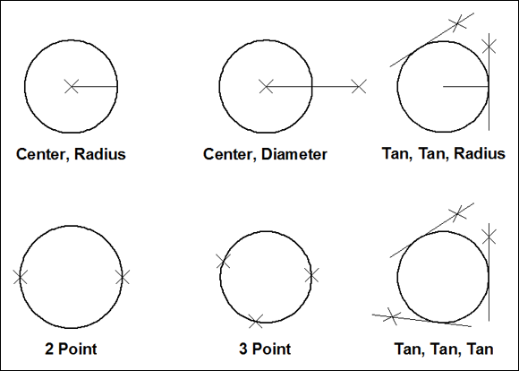
FIGURE 7-1: Pi R squared: Circles R round; pizzas are flat and round.
 Watch the command line. Pressing Enter repeats the last command; it doesn’t repeat the options of the last command. If you draw a circle by using the Ttr option, for example, pressing Enter doesn’t repeat that method; instead, it repeats the Circle command in its default radius mode.
Arc-y-ology
An arc is simply a piece of a circle. On the other hand, if you want a boat full of animals, you can use AutoCAD to design an ark.
![]() AutoCAD offers you an easy way to define arcs. Just start the Arc command, and then specify three points onscreen to define the arc: where to start the arc, how much to curve it, and where to end it. Easy, right?
AutoCAD offers you an easy way to define arcs. Just start the Arc command, and then specify three points onscreen to define the arc: where to start the arc, how much to curve it, and where to end it. Easy, right?
The trouble is that you nearly always need to specify arcs more precisely than is possible by using this method. AutoCAD helps you specify such arcs by allowing a total of 12 generous option combinations.
To experiment with all the available options, start the Arc command, and specify a start point or choose the Center option. AutoCAD prompts you first for the center point and then for the start point. AutoCAD normally draws arcs in a counterclockwise direction, so pick a start point in a clockwise direction from the endpoint.
On the other hand, after you pick the first point, AutoCAD offers two more options: the included angle and the chord length (the straight-line distance) from the start point to the end point.
To get a feel for how these permutations can be strung together to create different arc-drawing methods, click the down arrow below the Arc button on the Draw panel of the Ribbon to unfurl the drop-down menu, as shown in Figure 7-2. Using the Ribbon is also the most direct way to use these options, at least until you’re truly familiar with the program and you’re adept at entering keyboard shortcuts.

FIGURE 7-2: A deluge of Arc options, and the results of using some of them.
The Arc command draws counterclockwise from the start point. Over the years, so many people (novice and expert alike) have been confused by “arcs go counterclockwise” that AutoCAD 2014 introduced this option: If you press and hold down the Ctrl key while selecting the end point, AutoCAD draws the arc in a clockwise direction. A bit of experimenting and cursing will show you what I mean.
As usual, whenever AutoCAD asks for the first point, you can simply press Enter to automatically select the last point you specified, even if it’s from a different command. Arc has an added twist, however: If the previous point was at the end of a line, a polyline, or another arc, the new arc automatically starts from that point and is tangent to the previous object.
The converse is also true. Draw an Arc and start the Line command. When the command line asks for a starting point, press Enter to make the new line tangent to the end of the arc.
You probably don’t need to use the Arc command often. The Fillet, TRim, and BReak commands (discussed in Chapter 11) cover the vast majority of arc-creation needs.
Solar Ellipses
In case you’ve forgotten your ninth grade math, an ellipse is sort of a squished circle although it may be more accurate to say that a circle is an unsquished ellipse. Please excuse the technical jargon. Mathematically, an ellipse is defined by a major (long) axis and a minor (short) axis. These axes determine the ellipse’s length, width, and degree of curvature. An elliptical arc is an arc cut from an ellipse.
![]()
![]() The AutoCAD ELlipse command provides a straightforward way to draw an ellipse: You specify the two endpoints of one of its axes and then specify an endpoint on the other axis. Like the Arc command, however, the ELlipse command offers several other options:
The AutoCAD ELlipse command provides a straightforward way to draw an ellipse: You specify the two endpoints of one of its axes and then specify an endpoint on the other axis. Like the Arc command, however, the ELlipse command offers several other options:
- Arc: Generates an elliptical arc, not a full ellipse. You define an elliptical arc just as you define a full ellipse. The methods I discuss in this section for creating an ellipse apply to either one.
- Center: Requires that you define the center of the ellipse and then the endpoint of an axis. You can then either enter the length of the other axis or specify that a rotation around the major axis defines the ellipse. If you choose the latter option, you can enter (or drag the ellipse to) a specific rotation angle for the second axis that, in turn, completely defines the ellipse.
- Rotation: Specifies an angle that defines the curvature of the ellipse — small angles create wide ellipses (0 degrees creates a circle, in fact), and large angles make thin ellipses. After dinner, when your plate is empty, hold it vertically to look at it straight on. It looks like a circle. Slowly rotate the plate about its vertical axis until you’re looking at it edge-on. Between these two views, you will see every possible ellipse as defined by the rotation angle — and your dinner guests will begin to wonder about you.
![]() The following command line example creates an ellipse by using the default endpoints of the axes method. Enter ELlipse and press Enter or click the Ellipse button on the Ribbon:
The following command line example creates an ellipse by using the default endpoints of the axes method. Enter ELlipse and press Enter or click the Ellipse button on the Ribbon:
Specify axis endpoint of ellipse or [Arc/Center]: Pick or type the first endpoint of one axis.
Specify other endpoint of axis: Pick or type the other endpoint of one axis.
Specify distance to other axis or [Rotation]: Pick or type the endpoint of the other axis.
Figure 7-3 shows an ellipse and an elliptical arc.

FIGURE 7-3: To make an omelet, sometimes you have to break a few ellipses.
You can create elliptical arcs (as opposed to the circular arcs that the Arc command draws) by using the Arc option of the ELlipse command; it can draw a respectable representation of a snowball trajectory, neglecting air resistance. Alternatively, you can draw a full ellipse and use the TRim and BReak commands, discussed in Chapter 11, to cut a piece from it.
Splines: Sketchy, Sinuous Curves
Most people use CAD programs for precision drawing tasks: straight lines, carefully defined curves, and precisely specified points, for example. You may believe that AutoCAD is not the appropriate program to free your inner artist (unless your inner artist is Mondrian) — nonetheless, even meticulously created CAD drawings sometimes need free-form curves. In fact, the advent of processes such as computer numerical control (CNC) machining and 3D printing mean that many consumer goods and even quite a few industrial products are taking on smoother free-form shapes. The AutoCAD spline object is just the tool for the job.
You can use AutoCAD splines in one of two ways:
- Wing it. Eyeball the location and shape of the curve, and don’t worry about making it just so. That’s the free-form, sketchy, less-than-precise approach described in this section.
- Be precise. Specify the control points and curvature characteristics precisely.
Beneath the easygoing, informal exterior of the AutoCAD spline lies the truly highly precise, mathematically defined entity known as the Non-Uniform Rational B-Spline curve — the NURBS curve – wherein a B-Spline is a generalization of the Bézier curve. You can always go to http://mathworld.wolfram.com/B-Spline.html to learn far too much about B-splines. Mathematicians and mechanical and industrial designers often care deeply about the precise characteristics of the curves they work with. For these people, the AutoCAD SPLine and SPLINEDIT commands include a number of advanced options. Look up spline curves in the AutoCAD online Help system if you need precision splines.
Drawing a spline is straightforward, if you ignore the advanced options. Follow these steps to draw a free-form curve by using the SPLine command:
- Start a new drawing.
-
Click the Spline Fit button on the Draw panel slideout of the Home tab, or type SPL and press Enter.
AutoCAD starts the SPLine command and prompts you to specify the start point of the spline. The command line shows:
Current settings: Method=Fit Knots=ChordSpecify first point or [Method/Knots/Object]: -
Specify the start point by clicking a point or typing coordinates.
AutoCAD prompts you to specify additional points:
Enter next point or [start Tangency/toLerance]: -
Specify additional points by clicking or typing coordinates.
After you pick the second point, press the down-arrow key to display additional options at the Dynamic Input tooltip. You can turn on Dynamic Input from the status bar or by pressing the F12 key. The command line displays:
Enter next point or [end Tangency/toLerance/Undo/Close]: Because you’re drawing a free-form curve, you usually don’t need to use object snaps or other precision techniques to pick spline points, except perhaps at the start and end of the spline. I discuss precision techniques in Chapter 8. -
Press Enter after you choose the endpoint of the spline.
AutoCAD draws the spline.
You can specify the start and end tangency of the spline to control the curvature of the start points and endpoints of the spline. If all you want is a swoopy, free-form curve, picking only points works well.
Figure 7-4 shows examples of splines.
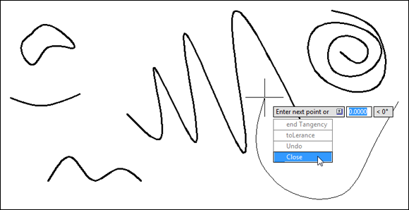
FIGURE 7-4: A slew of splines.
After you draw a spline, you can grip-edit it to adjust its shape. (See Chapter 11 for information about grip-editing.) If you need finer control over spline editing, look up the SPLine Edit command in the AutoCAD online help system.
The Polyline Edit (PEdit) command can convert a straight-line-segmented polyline into a spline curve form. I cover polylines in Chapter 6, and I touch on PEdit in Chapter 11.
Donuts: Circles with a Difference
Don’t tell Homer Simpson, but there’s no such thing as a donut in AutoCAD. A donut in AutoCAD is simply a closed polyline consisting of two 180-degree arc segments that you create with (what else?) the DOnut command. By the way, the rectangles and regular polygons described in Chapter 6 are also polyline objects. A common use for the DOnut command is drawing component-mounting pads on printed-circuit boards; a common use for donuts is as a snack during your coffee break.
When you start the DOnut command, AutoCAD prompts you for the inside diameter and the outside diameter (the size of the hole and the size of the donut) as measured across their widest points. After you’ve entered these values, AutoCAD prompts you for the center point of the donut. But one donut is rarely enough, so AutoCAD continues prompting you for additional center points until you press Enter. It’s the AutoCAD equivalent of saying, “No, really — I’m full now.”
![]() The following example draws a regulation-size donut, with a 1.5-inch hole and a 3.5-inch outside diameter. Enter DOnut and press Enter or click the Donut button on the Ribbon. You’ll find this button on the slideout panel below the Draw panel of the Home tab of the Ribbon.
The following example draws a regulation-size donut, with a 1.5-inch hole and a 3.5-inch outside diameter. Enter DOnut and press Enter or click the Donut button on the Ribbon. You’ll find this button on the slideout panel below the Draw panel of the Home tab of the Ribbon.
Specify inside diameter of donut <0.5000>: 1.5
Specify outside diameter of donut <1.0000>: 3.5
Specify center of donut or <exit>: Pick or type the center point of one or more donuts.
You can use the DOnut command to create a filled circle, also known as a jelly-filled donut. (Seriously!) Simply specify an inside diameter of 0 (zero). Figure 7-5 shows both kinds of donuts.

FIGURE 7-5: Donuts, plain and jelly-filled.
If you’re Canadian, the DOughnut command also works but TimHortons doesn’t (unless you use the ALIASEDIT command from Express Tools to create it as a new alias).
Revision Clouds on the Horizon
In many industries, designers and drafters customarily submit a set of drawings at different project milestones or stages of completion and then submit them again later with revisions, such as corrections, clarifications, and requested changes. Usually, the recipients of these drawings easily locate information that has changed, and a common drafting convention calls attention to revised items by drawing free-form clouds around them. The REVCLOUD command makes quick work of drawing these clouds.
Drawing revision clouds is easy, after you understand that you click only once in the drawing area. That single click defines the starting point of the cloud’s perimeter. Then you simply move the cursor around and the cloud takes shape. When you return to a spot near the point you first clicked, AutoCAD automatically closes the cloud.
![]() The following command line example shows you how to draw a revision cloud. Press the REVCLOUD button on the Markup panel of the Annotate tab, or enter REVCloud and press Enter:
The following command line example shows you how to draw a revision cloud. Press the REVCLOUD button on the Markup panel of the Annotate tab, or enter REVCloud and press Enter:
Minimum arc length: 0.5000 Maximum arc length: 0.5000 Style: Normal Type: Freehand
Specify first point or [Arclength/Object/Rectangular/Polygonal/ Freehand/Style/Modify] <Object>:
If the Type is indicated as anything other than Freehand, type F and press Enter.
Pick a point along the perimeter of your future cloud.
Guide crosshairs along cloud path… Sweep the crosshairs around to define the cloud's perimeter.
Don’t click again. Simply move the crosshairs around without clicking. AutoCAD draws the next arc segment of the cloud when the crosshairs reach the minimum arc length distance from the end of the previous arc segment.
Continue moving the crosshairs around until you return close to the point where you first clicked. AutoCAD will automatically draw one last arc to close the loop.
AutoCAD 2016 added three Type options to revision clouds:
- Object: Pick an existing rectangle, polyline, circle, line, or arc, and it turns into a revision cloud.
- Rectangular: Pick two points, and AutoCAD draws a rectangular revision cloud.
- Polygonal: Pick a series of points, and AutoCAD connects them with straight-line wavy sections.
If the revision cloud’s arcs are too small or too large, erase the cloud, restart the REVCLOUD command, and use the command’s Arc Length option to change the minimum and maximum arc lengths. The default minimum and maximum lengths are 0.5 (or 15 in metric drawings). If you make the minimum and maximum lengths equal (the default setting), the lobes are approximately equal. If you make them unequal, the lobe size will vary more, and you’ll create fluffier clouds. Finally, if you change the Style to Calligraphy, each arc section will taper down its length. Fortunately, these options are more than most non-meteorologists need.
Figure 7-6 shows various revision cloud types and styles.
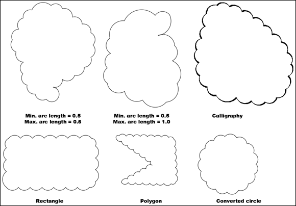
FIGURE 7-6: Today’s forecast: Revision cloudy.
Here are a few tips for using revision clouds:
- Create a cloud layer. Place a revision cloud on its own layer (as described in Chapter 9) so that you can choose to plot with or without the clouds visible. In the days of paper and pencils, revision clouds were sketched on the back of the drafting vellum so that they could easily be erased.
- Turn off Ortho mode. To more easily control the shape of a revision cloud, turn off Ortho mode before you start the command.
- Include the revision number. Common practice is to delete revision clouds with each new release of a drawing, but your company’s policy may be to leave them on, tagged with the revision number. A good way to handle this requirement is to use a new revision cloud layer for each new release.
Scoring Points
I considered skipping a description of points in this book, but I didn’t want you to complain that AutoCAD For Dummies was pointless.
The word point describes two different elements in AutoCAD:
- A location in the drawing that you specify (by typing coordinates or clicking with the mouse)
- An object that you draw by using the POint command
Throughout this chapter, and most of this book, whenever I tell you to specify points, I’m usually referring to the location. This section tells you how to draw POint objects.
A POint object in AutoCAD can serve one of two purposes:
- Identify a specific location in a drawing to other people viewing the drawing: A point can be displayed onscreen, as either a tiny dot or another symbol, such as a cross enclosed in a circle.
- Serve as a precise object snap location: Think of it as a construction point. For example, when you’re laying out a new building design, you might draw point objects at several engineering survey points and then snap to those points as you sketch the building’s shape with the PLine command. You use NODe Object Snap mode to snap to AutoCAD point objects. I discuss Snap modes in Chapter 11.
The factor that complicates AutoCAD point objects is their almost limitless range of display options, provided to accommodate these two purposes and possibly some others that I haven’t figured out yet. You use the Point Style dialog box, shown in Figure 7-7, to specify how points should look in the current drawing.
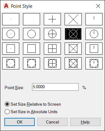
FIGURE 7-7: You use the Point Style dialog box to control how point objects appear onscreen.
To open the Point Style dialog box, open the Utilities panel slideout on the Home tab, or type its command name, DDPTYPE, which has to be one of the least intuitive command names in all of AutoCAD. The upper half of the dialog box shows the available point display styles. Most of the choices do much the same thing — just select one.
Avoid the first two choices if you want point objects to show up onscreen and on plots. The first choice, a single-pixel dot, is hard to see onscreen, and the second choice, which is invisible (a stealth point?), is impossible to see. The single-pixel dot, which is the default display style, works well if you use point objects as object snap locations and want to omit obtrusive points on plots.
The remaining settings in the Point Style dialog box control the size at which points appear onscreen at different zoom magnifications. The default settings often work well, but if you’re not satisfied with them, click the Help button in the dialog box to find out how to change them.
![]() After you specify the point style, placing POints onscreen is easy. Simply type POint at the command line and press Enter to see this prompt:
After you specify the point style, placing POints onscreen is easy. Simply type POint at the command line and press Enter to see this prompt:
Current point modes: PDMODE=0 PDSIZE=0.0000
Specify a point: Pick or type the coordinates of a location in the drawing.
The PDMODE and PDSIZE items listed in the command line are system variables that correspond to the point display mode and display size options in the Point Style dialog box. If you want to know exactly how the system variables correspond to the dialog box choices, you have all the makings of a successful CAD nerd. Click the Help button in the Point Style dialog box to find out more about system variables — not about yourself.