
Analog Demystified
To get our heads around the concept of what analog is, we should compare the difference between analog and digital signals beginning with Figure 6-1.
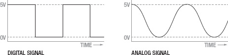
Figure 6-1. Digital versus analog signals
Looking at these two graphs that show the effect of the different signals types over time, you can see that where a digital signal abruptly shifts from high to low, an analog signal can gradually move through a multitude of steps in between these two extremes. This varying, or analog signal, is what we can use to determine how cold it is, how much pressure is being exerted, or to change the brightness of a light or the speed of a motor. In order for the digital microcontroller that likes 1s and 0s to be able to input and output analog signals we need to use some additional hardware built onto the chip to convert or interpret these signals for us.
In order to receive an analog input, we need to use the microcontroller's analog to digital converter, usually called an A/D converter or ADC, to convert a continuous analog voltage applied to one of the analog pins into a digital integer proportional to the amount of voltage at that pin. This is a specialized bit of hardware that is connected to 6 of Arduino's general I/O pins, marked on the board as A0–A5. The Arduino ADC has a 10-bit resolution, meaning that it will return a linear value from 0 to 1023 corresponding to 0v and +5v respectively. With this resolution, the Arduino ADC can read levels of voltage down to 4.88 millivolts per level. Keep in mind, however, that where an analog signal is a continuous signal, the ADC will only take a single reading at the very instant that the function is called.
Because it is a digital device, the Arduino is actually incapable of providing a true analog output. Instead, it approximates an analog signal by turning on and off a pin very quickly in a process called pulse width modulation (PWM). This happens so fast it is nearly imperceptible to the eye, instead looking like a dim LED or a slow motor. The hardware that does this is connected to pins 3, 5, 6, 9, 10, and 11 on the Arduino Uno and has an 8-bit resolution, meaning that values between 0 and 255 will simulate voltages between 0v and +5v. While not a smooth continuous analog signal, by alternating the amount of time that the pin is on, or its pulse width, in relation to the time off, it will emulate an analog signal. The average voltage created by quickly alternating between on and off is called the duty cycle as illustrated in Figure 6-2.

Figure 6-2. Pulse width modulation duty cycle
Figure 6-2 shows how a PWM signal that is on, or +5v, for 75% of the time and off, or 0v, for 25% will simulate an analog voltage of +3.75v. This would be referred to as a 75% duty cycle. Likewise, a duty cycle of 15%, where the pin is on for 15% of the time and off 85% of the time, would result in only an average of +0.75v. This is how we can use PWM to give an LED the appearance of fading or with the right hardware to change the speed of a motor. Now that we have a handle on how analog works on the Arduino, let's look at our next project.