Project 8: Decision Machine
Holding our completed project in your hands, you might ask it a simple question before giving it a gentle shake and at that moment a forecast will mystically appear from the murky depths of its display. If that sounds familiar, it's because we loosely found inspiration for this project in a classic, sometimes irreverent, fortune-telling icon. Our prototype design uses an accelerometer to recreate the familiar rotate or shake to activate the device, and an LCD to provide us with the short but erudite answers to our imagined yes-or-no questions. To make it interesting, we will use arrays throughout our project to give us something to talk about in this chapter and to demonstrate how arrays work in our code.
Hooking It Up
With only few components to hook up, this project is not overly complex, although you will need lots of hookup wires. To display our fortune, we are using a 16 × 2 backlit character liquid crystal display or LCD. Ours has a black background with bright white text for effect and can display two rows of 16 characters each. This display uses the venerable HD44780 interface controller that has been around for ages, making it super easy to display text using the Arduino. Our circuit is fairly standard, using six digital pins to interface with the LCD with two little differences. First, we need to connect a 2.2 kilohm resistor from the contrast pin marked V0 in the schematic to ground. This pin controls the contrast for the LCD and is usually connected to a potentiometer to allow for manually adjusting the contrast of the screen. By using a single resistor, we keep things a little simpler. Secondly, to add theatricality, we are connecting the positive or anode pin of the LED backlight to PWM pin 11. With the analogWrite() function, we can fade the answer in and out of existence to simulate the smarmy answers emerging from the murky depths of the display. As usual, we could substitute many other versions of this LCD in different colors or even sizes, as long as it uses the same interface chip.
To detect the customary shake or rotation of the device after a question has been asked, we will use a 3-axis analog accelerometer, which fittingly enough is a device used to measure acceleration or the change in speed or movement along multiple axes. Our particular version is the ADXL335 from Analog Devices that provides an analog voltage corresponding to acceleration in the X, Y, or Z-axis. Because the chip is so small and not very breadboard friendly, we are using the breakout board available from SparkFun Electronics. This breakout board is the first device that needs pin headers or wires soldered to the device to work with our breadboards. For more on this topic, refer to the section on soldering in Chapter 12 With these in place, the connection is simple enough with an output from each of the three axes to three analog in pins marked A0, A1, and A2. Because this device runs on +3.3 volts we need to connect its positive power pin marked VCC to the Arduino interface board's 3.3V output pin. A number of other analog accelerometers would work just as well, but the code might need to be modified for fewer axes or if the accelerometer used some other communication protocol.
One last thing to be aware of is that to simplify wiring a little bit, we are making use of the ground bus on the side of the breadboard, usually marked by a blue line and a “-” sign. The neat thing about this row of pins is that they connect horizontally along the length of the board unlike the other pins that we have used so far. Not all breadboards have these, so you might need to adjust your wiring appropriately. Remember to take your time with the wiring to make sure the wires go to the correct pins. Figures 8-1 and 8-2 show how to hook up this project.

Figure 8-1. Decision Machine schematic
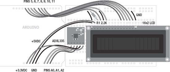
Figure 8-2. Decision Machine illustration
Uploading the Source Code
While you might think this sketch is a bit intimidating and lengthy, in reality it's not too bad because most of it is white space. Half of the source code is tied up in listing the 20 possible answers that could be displayed each time the device is shaken or rotated. The rest builds on prior projects to come before it by using many of the functions and structures used in past sketches. We've stuck with some answers that might seem familiar as a starting point, but you should definitely make up your own answers. To get things to line up in the center of the screen, each answer is written as two lines of 16 characters using spaces as appropriate to center each line on the screen.
To compartmentalize our code a bit, we have created three new functions. The first function, named getReading(), reads the three analog inputs for each of the axes on the accelerometer. The second, oldReading(), keeps track of the last sensor readings so that we can determine if a threshold has been crossed. Finally, getAnswer() generates a random answer from the 20 possible, gets the message text to be displayed, and then sends that message out to the LCD display. To create a sense of drama, this function will also fade the display up to full brightness and then back again to darkness to simulate the response bubbling up from the aether within. Before we get into how this all works, we need to wire up the circuit, upload the source code in Listing 8-1, and see what happens.
Listing 8-1. Decision Machine Source Code
#include <LiquidCrystal.h>


char* allAnswers[] = {

"  As I see it,  ",

"      yes       ",


"     It is      ",

"    certain     ",
"     It is      ",

"  decidedly so  ",


"      Most      ",

"     likely     ",


"    Outlook     ",

"     good       ",


"  Signs point   ",

"    to yes      ",


"    Without     ",

"    a doubt     ",


"      Yes       ",

"                ",


"      Yes -     ",

"   definitely   ",


"    You may     ",

"   rely on it   ",


"   Reply hazy,  ",

"    try again   ",


"    Ask again   ",

"     later      ",


"   Better not   ",

"  tell you now  ",


"    Cannot      ",

"  predict now   ",


"  Concentrate   ",

" and ask again  ",


"  Don't count   ",

"     on it      ",


"    My reply    ",

"     is no      ",


"  My sources    ",

"    say no      ",


"  Outlook not   ",

"    so good     ",
"      Very      ",

"  doubtful      "   };


LiquidCrystal lcd(5, 6, 7, 8, 9, 10);


const int backlight = 11;

const int axisPin[] = {A0, A1, A2};


const int threshold = 60;

const int brightness = 175;


int axis[3];

int oldAxis[3];


void setup() {

  lcd.begin(16, 2);

  randomSeed(analogRead(A5));

  getReading();

  oldReading();

}


void loop() {

  getReading();

  if (abs(axis[0]-oldAxis[0]) > threshold ||

      abs(axis[1]-oldAxis[1]) > threshold ||

      abs(axis[2]-oldAxis[2]) > threshold) {

   getAnswer();

   delay(500);

   getReading();

   oldReading();

  }

  delay(125);

}


void getReading() {

  for (int i=0; i<3; i++) axis[i] = analogRead(axisPin[i]);

}


void oldReading() {

  for (int i=0; i<3; i++) oldAxis[i] = axis[i];

}


void getAnswer() {

  int thisAnswer = random(40);

  while (thisAnswer % 2 != 0) thisAnswer = random(40);


  lcd.setCursor(0, 0);

  lcd.print(allAnswers[thisAnswer]);

  lcd.setCursor(0, 1);

  lcd.print(allAnswers[thisAnswer+1]);
  for (int i=0; i<=150; i++) {

    analogWrite(backLight, i);

    delay(30);

  }

  for (int i=150; i>=0; i--) {

    analogWrite(backLight, i);

    delay(30);

  }

  lcd.clear();

}
Source Code Summary
With that out of they way, we should have an Arduino connected to a breadboard through a slew of wires and … nothing actually happens. That is at least until we shake the thing or turn it upside down when an answer will illuminate briefly before fading away again. Now, let's see how it does that.
Inclusions and Declarations
The first line enables the LiquidCrystal library that gives us some easy to use code for talking to LCDs:
#include <LiquidCrystal.h>
We'll get to libraries in more depth when we talk about LiquidCrystal among other hardware libraries in the next chapter. Following this line is the first of our declarations:
char* allAnswers[] = {

"  As I see it,  ",

"      yes       ",


"    It is       ",

"   certain      ",

.

.

.

"    Very        ",

"  doubtful      "   };
This page-long list of curious two-line answers is called a character array and contains all of the possible 20 answers that our Decision Machine might display. Each answer is spaced so that it will appear in the center of the LCD and some extra white space has been added to make each answer easier to read in code at the cost of extra paper. Each answer will be addressed by an index number elsewhere in our sketch. After defining our array of answers, we now need to set up the pins that we plan to use, as follows:
LiquidCrystal lcd(5, 6, 7, 8, 9, 10);

const int backlight = 11;

const int axisPin[] = {A0, A1, A2};
Like our previous sketches, these lines of code are the I/O pin numbers that we will use with our hardware. The first line tells the LiquidCrystal library which of the pins the LCD is connected to. The backlight pin is the built in LED on the LCD that we will fade in and out. Finally, axisPin[] is a numerical array that contains the three analog input pins used by the accelerometer.
const int threshold = 60;

const int brightness = 175;
These two lines are other configurable variables that determine how much movement needs to be detected before an answer is generated and the total brightness in the LCD backlight in the first and second line respectively.
int axis[3];

int oldAxis[3];
The last of our global variable declarations, axis[] and oldAxis[] are two arrays that we will use to keep track of which axis has been read and what the old values were the last time we read them. This will help to determine how much movement has been detected in shaking or rotating the device.
setup() and loop()
Our setup() function is fairly small:
lcd.begin(16, 2);

randomSeed(analogRead(A5));

getReading();

oldReading();
We begin with a function that starts up the LCD and tells it how big it is, in this case 16 ? 2 characters. We then seed the random function with a reading from analog in pin A5 with nothing connected to it. Next, we take a quick reading from the accelerometer and set these as the old values using two of our functions, getReading() and oldReading(). We will look at these more after we talk about the loop() function.
getReading();

  if (abs(axis[0]-oldAxis[0]) > threshold ||

      abs(axis[1]-oldAxis[1]) > threshold ||

      abs(axis[2]-oldAxis[2]) > threshold) {
Because we have sufficiently compartmentalized our code using functions, the loop() function is also fairly compact. We begin with reading the sensor values first. The second, third, and fourth lines will check to see if our threshold has been exceeded on any axis by subtracting the old values from the newest values and testing the difference. We've used the abs() function to get the absolute value of this difference because we could have positive or negative values here, but we only want to know the difference. Using abs() saves us from having to also check if the old values are larger than the new values because it's only the amount the values change that we are really interested in.
getAnswer();

delay(500);

getReading();

oldReading();
If a sufficient amount of movement has been detected then we will launch our third function getAnswer() to generate a random message on the LCD. After that has completed, we pause for a half second to give the accelerometer a chance to calm down and then we make another reading and move the new values to the old reading just like we did in setup() to create a baseline for our sensor readings.
delay(125);
The last line in loop() is just a short eighth of a second delay to slow things down just enough. You probably have noticed that nowhere in this sketch do we know what the actual values of the sensor are. That's not really important only the amount of change, either smaller or larger, in the sensor value. So, let's look at our three new functions.
Functions
Of our three new functions, the first one that we've used is getReading():
void getReading() {

  for (int i=0; i<3; i++) axis[i] = analogRead(axisPin[i]);

}
This function is a simple for loop that will read each analog pin as defined by the axisPin[] array and assign those readings to each of the 3 positions in the axis[] array. More on how that works briefly.
void oldReading() {

  for (int i=0; i<3; i++) oldAxis[i] = axis[i];

}
Like the last function, oldReading() uses a for loop to assign the current values in the axis[] array to the same index positions in the oldAxis[] array. This way we can keep track of the old readings so that we can detect when a sufficient amount of change has occurred.
void getAnswer() {

  int thisAnswer = random(40);

  while (thisAnswer % 2 != 0) thisAnswer = random(40);
Our final function has a lot going on beginning with choosing a random number in the range of 0 to 39. Even though we only have 20 answers, each answer is split into two lines so we want to start with an even number when displaying the first half of an answer. This means that we need to get 40 answers and then using a while loop, we can check to see if the random value is an odd or even number. By dividing the random number by 2, we know that we've got an even number when it is equal to 0. If it were an odd number we would start displaying our decision in the middle of our message so instead we have it try again at getting a random even number before moving on.
lcd.setCursor(0, 0);

lcd.print(allAnswers[thisAnswer]);

lcd.setCursor(0, 1);

lcd.print(allAnswers[thisAnswer+1]);
Once we have a number for our answer, these four lines will print the first line of the answer, move to the second line of the display, add one to our answer index, and then display the second line of our answer.
for (int i=0; i<=brightness; i++) {

    analogWrite(backLight, i);

    delay(30);

  }

  for (int i=brightness; i>=0; i--) {

    analogWrite(backLight, i);

    delay(30);

  }

  lcd.clear();
So far, all of this code has happened and still nothing can be seen on the screen! To actually see the answer, we need to fade the backlight from 0 or off all the way up to the brightness level determined at the top of the sketch. Once we hit the brightness level, we fade it back down to off again and clear the LCD. We could just connect the LED pin to +5v instead, but where would the fun be in that? This little addition to the code creates much more intrigue and theatricality. Try it without it and I bet you won't like it as much.
With that rather convoluted explanation out of the way, let's back up and talk more specifically about how arrays work. We will also look at some different kinds of arrays and then discuss how these arrays affect the memory usage on the Arduino microcontroller. Hopefully after looking at the way the memory works, there will be reason enough for going back to figure out how we can utilize program memory better.