
Analog Functions
The analog functions are a little different from the digital ones. First, as we discussed earlier, they do not need to be set up using pinMode() beforehand. Second, we are dealing with integer numbers that range from 0 to 255 or 0 to 1023, rather than digital states like HIGH and LOW, so we need to keep that in mind while working with them. So anyway, let's proceed onward with a discussion of the analog functions.
analogRead()
The counterpart to the digitalRead() function, analogRead() is equally as simple at first. Its syntax follows:
analogRead(pin)
When we call this function, we need to specify the analog pin that we are reading data from, in the format of A0–A5. The “A” is placed in front of the pin number to remind us that we are using one of the analog input pins, also marked on the board A0–A5. The reading returns a 10-bit value with a range of integers from 0 to 1023 corresponding to the input voltage on the pin.
Also like the digitalRead() function, what we do with this value depends on the context in which we use the function. This includes assigning the reading to a variable to be used later in the code or to use the function in place of a variable. A common usage of this function to assign a value to a variable would appear as follows:
Or we might use the function inside another. Say for instance, we wanted our pin 13 LED to blink slowly when it was dark and quickly when there was light. With a light sensor connected to pin A0, our code could look as follows:
delay(analogRead(A0));
Here we will delay for the amount of time as specified by the integer received from analog input pin A0 in an amount from 0 to a little over 1 second. To extrapolate this into a full code example, have a look at Listing 6-2.
Listing 6-2. analogRead() Example
int analogValue = 0;

int ledPin = 13;


void setup() {

  pinMode(ledPin, OUTPUT);

}


void loop() {

  analogValue = analogRead(A0);

  digitalWrite(ledPin, HIGH);

  delay(analogValue);

  digitalWrite(ledPin, LOW);

  delay(analogValue);

}
This is the basic blink sketch, except now the LED will blink slowly when an analog sensor provides a low-voltage reading and blink quickly when the sensor provides a higher voltage reading. This works by adding an analogRead() statement that assigns an analog value to the variable analogValue that we use as a length of time in the delay() function. What analog sensor is used for in this example is up to you, but our wind sensor from our project would work great. So, now that we can read these values, let's look at how can we output analog values.
analogWrite()
The function analogWrite() will allow us to access the pulse width modulation hardware on the Arduino microcontroller. The basic syntax for this function follows:
analogWrite(pin, duty cycle)
In using this function we need to give it two pieces of information. The first is the pin number, which can only include one of the following pins on the Arduino Uno: 3, 5, 6, 9, 10, and 11. These are marked as PWM on the interface board. Other versions of the Arduino may have fewer or more PWM pins available, so double-check your hardware's documentation. The second bit of information is the duty cycle expressed as an 8-bit numerical integer ranging between the values of 0 and 255. The value 0 corresponds to off or 0% duty cycle and 255 is basically full on or 100% duty cycle. Any value in between these two endpoints provides a corresponding duty cycle approximating an analog output.
It is a common practice to express the duty cycle value using a variable instead of a constant value. One way that we could do this would be to use a for loop, as in the following code sample:
for (int i=0; i<=255; i+=5) {

  analogWrite(5, i);

  delay(20);

}
This sample code uses a for loop to increment a counter, i, in steps of five beginning with 0 and ending with 255. This value expressed as a variable is then output to PWM pin 5 using analogWrite() followed by a brief 20-millisecond delay. If connected to an LED, this would have the effect of starting with the LED off and gradually increasing brightness until the LED was at full brightness. Likewise, if we used our fan circuit, the fan would start at off and increase in speed until it is spinning at full speed.
We could even combine analog output with analog input, as in the following simple sketch in Listing 6-3.
Listing 6-3. analogWrite() Example
int analogValue = 0;

int ledPin = 5;


void setup() {

}


void loop() {

  analogValue = analogRead(A0) / 4;

  analogWrite(ledPin, analogValue);

  delay(20);

}
This simple little sketch is the most basic form of our source code for the project, although if you try it you'll see it doesn't work quite as well. This code simply takes an analog reading and routes that value to an analog output. Again, there are no statements needed in the setup() function because we are using only analog functions.
One challenge that we face when using a value from an analog input and sending it to an analog output, is that the analogRead() function returns a value in the range of 0 to 1023, while analogWrite() only works with values in the range of 0 to 255. To get around this, when assigning the value to the variable analogValue in the first line of this most recent loop() function, we take the reading from analog pin A0 and divide this by 4 before assigning to our variable. All should work fine because 1024, the total number of possible values in a 10-bit reading, divided by 4 will result in 255, which is the maximum number of values that we can use in the 8-bit PWM function.
Now depending on the sensor we are using on our analog input, this may not result in either the most accurate or the prettiest results. To fix this, we will need to make use of some techniques and functions, some of which were used in our project earlier, to find out what our readings actually are and increase their accuracy, beginning with the next analog function and proceeding on through the rest of the chapter.
analogReference()
By using the analogRead() function, the Arduino assumes a voltage range of between 0v and +5v. Increasingly though, more and more sensors are using lower operating voltages from +3.3v to as low as +1.8v, and as a result, will only return values up to their maximum operating voltages. The Arduino interface board, however, has a convenient pin called AREF located near digital pin 13 along with a function called analogReference() to give the Arduino's ADC a reference voltage other than +5v. This function will effectively increase the resolution available to analog inputs that operate at some other range of lower voltages below +5v. The syntax for this function follows.
analogReference(type)
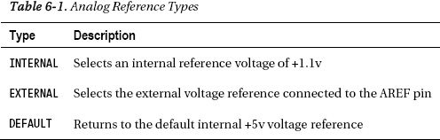
The function is only called once in a sketch, but must be declared before analogRead() is used for the first time, making it a suitable candidate for placing in the setup() function. The type specified relates to the kind of reference voltage that we want to use. There are three possible reference voltage types on the Arduino Uno to be used for analogReference(), as listed in Table 6-1.
While there are many reasons and methods for using a different voltage reference, many of these get very complex very quickly. The one we are most interested in providing is an external +3.3v reference when we use an accelerometer sensor to detect movement, discussed in greater detail in a later chapter. In order to get accurate readings from this sensor, we will make the following statement once at the beginning of our source code:
analogReference(EXTERNAL);
We will then need to connect the AREF pin to the output pin labeled 3.3V using a jumper wire. This will use the Arduino's Uno secondary onboard voltage regulator to provide an accurate external analog reference of +3.3v. With this setup, it is important to call the analogReference() function before the analogRead() function, or it is possible to short the internal and external voltages—perhaps damaging the microcontroller. Finally, it is also important to remember to never connect the AREF pin to a voltage source greater than +5v because it could also damage the microcontroller.