
CHAPTER 8
3D Game Programming Basics
In Chapter 2, we talked about 2D coordinate systems, including a special case of such systems: the screen coordinate system. When dealing with 3D coordinate systems, however, a lot more is involved with defining a 3D virtual object and transforming such an object into a 2D representation on the screen.
This chapter covers the basics of creating 3D games. First, you'll learn the fundamental concepts, and then you'll see how to apply them in a simple XNA project. This will prepare you for creating a complete 3D game in the next chapters.
Note XNA 3.0 currently does not support creating 3D games for Zunes.
3D Coordinate Systems and Projections
When dealing with three Cartesian dimensions, two types of coordinate systems are used: left-handed and right-handed. These names refer to the z axis's position relative to the x and y axes. To determine this position, point the fingers of one hand to the x axis's positive direction and move them in a counterclockwise direction to the y axis's positive position. The z axis's direction is the direction your thumb points to. Figure 8-1 illustrates this concept.
To put it a different way, in the left-handed coordinate system, the z value gets bigger (the positive direction) when you go from the screen to a point away from you (considering that the x axis and the y axis are on the computer screen). The right-handed 3D system is the opposite: the z values increase toward you from the screen.
The XNA Framework works, by default, in a right-handed coordinate system (which, it's worth noting, is different from DirectX's default). This means that negative values for the z axis are visible, and the more negative they are for a given object, the farther the object is from the screen. Positive values are not shown, unless you change your camera position, as you'll see later in this chapter.
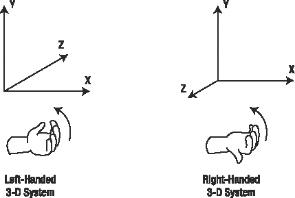
Figure 8-1. The Cartesian 3D coordinate systems
Now that you understand 3D coordinate systems, the next step to explore is how you can map 3D objects from this system to your computer (or Xbox 360) 2D screen.
Fortunately, XNA does all the hard mathematical work for this mapping, but you still need to understand the concept of projections and how they apply to XNA to issue the basic instructions for how to present the objects on the screen.
Similarly to other gaming libraries, XNA supports two different types of projections:
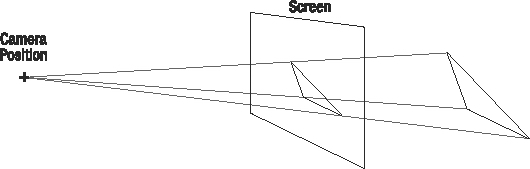
- Perspective projection:
- The most common type of projection, perspective projection takes the z distance into account and adjusts the objects accordingly. This projection makes objects appear smaller when far from the screen. Depending on the position, the objects also appear deformed, as in the real world. For example, the sides of a cube that are closer to the screen seem bigger than the farther ones. Figure 8-2 shows a graphical representation of the perspective projection.
Figure 8-2. Perspective projection
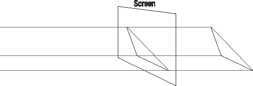
- Orthogonal projection:
- In this type of projection, the z component is just ignored, and the objects don't get bigger when closer to the screen or smaller when they are farther away. This projection is mostly used for 2D games (which may use "fake" 3D, just to put some sprites over others), to create head-up displays (HUDs, which are 2D interface elements such as life indicators, windows, and so on) or simpler 3D games. Figure 8-3 illustrates orthogonal projection.
Figure 8-3. Orthogonal projection
You'll see later in this chapter how to use each projection type in XNA. However, before you start coding, you need to understand how 3D objects are represented in a game, which is the topic of the next section.
Vertices and Primitives
The most basic part of a 3D object is a vertex. Mathematically, vertices are represented solely by their 3D coordinates (which are mapped to the Vector3 data type in XNA), but in XNA, they include extra information—such as color, texture, and normal vector information—depending on the vertex format used. Table 8-1 presents the default vertex definitions provided by the XNA Framework, which can be extended by the game developer if desired.
Table 8-1. Vertex Format Structure Definition in XNA
| Vertex Format | Description |
VertexPositionColor |
Defines a vertex with position and rendering color |
VertexPositionTexture |
Defines a vertex with position and texture coordinates, which specify how to map a given texture over this vertex, with (0, 0) being the upper-left coordinate of the texture, and (1, 1) the bottom-right limit of the texture |
VertexPositionColorTexture |
Defines a vertex with position, color, and texture coordinates |
VertexPositionNormalTexture |
Defines a vertex with position and the normal vector |
Along with the vertices' position and additional data, when creating 3D objects, you also need to specify how XNA will connect these vertices, according to different drawing primitives.
Note Drawing primitives are one of the three basic geometric primitives (points, lines, and triangles) used by XNA to render a collection of vertices. Depending on the primitive type chosen, the same set of vertices (known as the vertex buffer or vertex stream) will be rendered differently.
The triangle is used as a base to create any other 2D or 3D objects. This is because a primitive defined with only three points is guaranteed to be in a single plane and to be convex. (A line connecting any two points inside a triangle is always fully inside the triangle, which doesn't happen in some figures with four vertices.) These characteristics are the key to performing the fastest rendering possible by the graphics cards, which always use triangles as the base rendering primitives.
So, for example, if you want to draw a square on the screen, you'll use two triangles. If you want to create a cube, you'll use 12 triangles (2 for each facet), as shown in Figure 8-4.
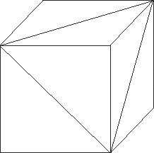
Figure 8-4. A cube made with triangles
In XNA, the graphics device object has a method named DrawPrimitives that is used to draw a vertex buffer according to a specific primitive type, defined by the PrimitiveType enumeration:
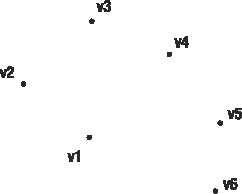
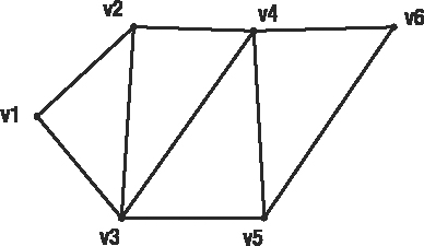
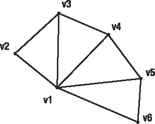
PointList: Each vertex is rendered isolated from the others, so you can see a list of floating points. Figure 8-5 presents a set of vertices rendered as a point list.
Figure 8-5. Vertices rendered as a point list
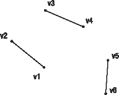
LineList: The vertices are rendered in pairs, with lines connecting each pair. This call fails if you do not pass a vertex buffer with an even number of vertices. Figure 8-6 illustrates the use of a line list primitive type.
Figure 8-6. The same vertices rendered as a line list
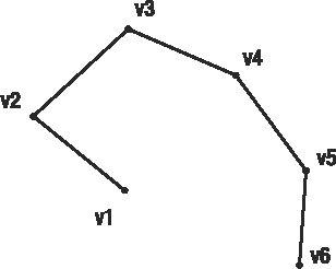
LineStrip: All the vertices in the buffer are rendered as a single, connected line. This can be useful when debugging, because this primitive type allows you to see a wireframe image of your objects, regardless of the number of vertices. Figure 8-7 presents a line strip primitive type sample.
Figure 8-7. The same vertices rendered as a line strip
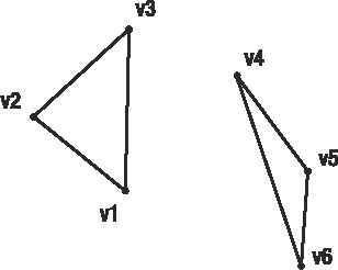
TriangleList: The vertices are rendered in groups of three, as isolated triangles. This provides you with the greatest flexibility when rendering complex scenes, but there's the drawback of having duplicated vertices if you want to draw connected triangles. Figure 8-8 shows the use of the triangle list primitive type to render vertices.
Figure 8-8. The same vertices rendered as a triangle list
TriangleStrip: You use this primitive type when drawing connected triangles. It's more efficient for rendering scenes, because you don't need to repeat the duplicated vertices. Every new vertex (after the first two) added to the buffer creates a new triangle, using the last two vertices. Figure 8-9 presents a triangle strip primitive type example.
Figure 8-9. The same vertices rendered as a triangle strip
TriangleFan: In this primitive, all the triangles share a common vertex—the first one in the buffer—and each new vertex added creates a new triangle, using the first vertex and the last one defined. Figure 8-10 illustrates the triangle fan type.
Figure 8-10. The same vertices rendered as a triangle fan
Note When drawing triangles, you need to take special care with the triangle vertex ordering if you want XNA to know which triangles are facing the camera and which ones are not. This is important when drawing complex objects such as a donut, for example, to prevent back polygons from showing. To determine the "front" side of a triangle, follow its vertices, from the first to the last one according to their definition order, with the fingers of your right hand. Your thumb will point to the front side of the triangle, just as you saw with the right-handed coordinate system (see Figure 8-1). Drawing only the triangle front faces is XNA's default behavior. You can change this behavior by setting the GraphicsDevice.RenderState.CullMode property.
Vectors, Matrices, and 3D Transformations
Before you're ready to create your first 3D program, you need to understand a few more concepts. 3D vectors and matrices are possibly the most important concepts in 3D game creation.
Vectors
Along with storing the positional values, vectors provide many helper methods that will come in handy when creating your games. Vector3 is the most commonly used vector in 3D games, and some of its most important methods are as follows:
Vector3.Distance: Given two points, returns afloatrepresenting the distance between them.Vector3.AddandVector3.Subtract: Add and subtract two vectors. You can also use the common plus (+) and minus (-) signs to perform addition and subtraction operations onVector3.Vector3.MultiplyandVector3.Divide: Multiply and divide two vectors, or a vector by afloatvalue.Vector3.Clamp: Constrains the vector components into a given range—useful when defining lights or matrices' values that support only values within a given range.Vector3.Lerp: Calculates the linear interpolation between two vectors.Vector3.SmoothStep: Interpolates two vectors according to afloatgiven as a weight value.
Additionally, Vector3 offers a series of shortcuts for special vectors, such as Vector.Zero for an empty vector, Vector3.Up for the (0, 1, 0) vector, Vector3.Right for the (1, 0, 0) vector, and others. Vector2 and Vector4 provide similar methods and shortcuts. Many of these methods and shortcuts are used when defining matrices and executing 3D operations.
Matrices
Matrices are the basis for defining rotation, scaling, and translation of an object in the 3D world. Because matrices are used to define any 3D transformations, they are also used to define the operations needed to simulate the projections (discussed earlier in the chapter) and to transform the 3D scene according to the camera position and facing direction.
You'll see examples of each of these uses when creating your sample program. For now, let's see the use of transformation matrices to do a simple translation, and then extrapolate the idea for more complex operations. This will help you understand the importance of the use of matrices in 3D programs.
Suppose you want to move a triangle up the y axis, as shown in Figure 8-11.
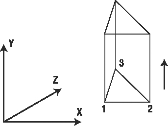
Figure 8-11. Moving a triangle on the y axis
Let's assume that the coordinates of the triangle vertices are as follows:
| Vertex | X | Y | Z |
| 1 | 50 | 10 | 0 |
| 2 | 70 | 10 | 0 |
| 3 | 55 | 25 | 0 |
To translate 40 units over the y axis's positive direction, all you need to do is to add 40 to each y position, and you have the new coordinates for the vertices, shown here:
| Vertex | X | Y | Z |
| 1 | 50 | 50 | 0 |
| 2 | 70 | 50 | 0 |
| 3 | 55 | 65 | 0 |
You can achieve the same results by representing each vertex as a matrix with one row and four columns, with the vertex coordinates as the first three columns and 1 as the value in the last one. You then multiply this matrix to a special matrix, constructed to produce the translation transformation to the vertex matrix.
Figure 8-12 presents the same operation applied to the first vertex.
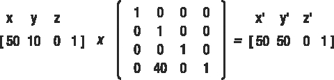
Figure 8-12. Applying a matrix multiplication to a 3D vertex
A little explanation about multiplication for matrices is in order. To calculate the resulting matrix, you must take each value in the row of the first matrix, multiply it by each of the values in the corresponding column in the second matrix, and then sum all of the results. So, in the previous sample, the calculations are as follows:
- x' = (50 × 1) + (10 × 0) + (0 × 0) + (1 × 0) = 50
- y' = (50 × 0) + (10 × 1) + (0 × 0) + (1 × 40) = 50
- z' = (50 × 0) + (10 × 0) + (0 × 1) + (1 × 0) = 0
Put simply, you can perform translations by putting the desired values for translation over the x, y, and z positions in the last row of the transformation matrix. You can perform scaling by replacing the 1s on the diagonal with fractional values (to shrink) or values bigger than 1 (to expand), and perform rotation around any axis using a combination of sine and cosine values in specific positions in the matrix.
So, what's the big deal about using matrices? One of the biggest benefits is that you can perform complex operations by multiplying their corresponding transformation matrices. You can then apply the resulting matrix over each vertex on the 3D model, so you can perform all operations on the model by multiplying its vertices for only one matrix, instead of calculating each transformation for each vertex. For example, usually you will need to rotate, scale, and translate an object to position it in your 3D scene, and then perform new operations according to the object's movement around the scene. In this situation, instead of calculating all operations for each vertex, you multiply the transformation matrices and calculate only one operation per vertex: multiplying it by this resulting matrix.
Even better, all graphics cards have built-in algorithms to multiply matrices, so this multiplication consumes little processing power. Considering that complex 3D objects may have thousands of vertices, doing the transformations with as low a processing cost as possible is a must, and matrices allow this.
Fortunately, you don't need to understand all these mathematical details to use matrices and execute 3D transformations in your program. All game programming libraries (from OpenGL to DirectX) offer ready-to-use matrix manipulation functions, and XNA is no exception. Through the Matrix class, many matrix operations are available, such as the following:
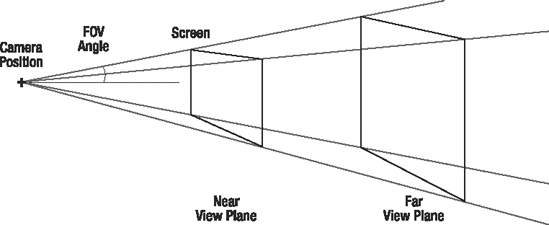
Matrix.CreateRotationX, Matrix.CreateRotationY, andMatrix.CreateRotationZ: Each of these creates a rotation matrix for each of the axes.Matrix.Translation: Creates a translation matrix (one or more axes).Matrix.Scale: Creates a scale matrix (one or more axes).Matrix.CreateLookAt: Creates a view matrix used to position the camera, by setting the 3D position of the camera, the 3D position it is facing, and which direction is "up" for the camera.Matrix.CreatePerspectiveFieldOfView: Creates a projection matrix that uses a perspective view, by setting the angle of viewing (field of view), the aspect ratio (the ratio used to map the 3D projection to screen coordinates, usually the width of the screen divided by the height of the screen), and the near and far planes, which limit which part of the 3D scene is drawn. See Figure 8-13 to better understand these concepts. Similarly, you have two extra methods,CreatePerspectiveOffCenterandCreatePerspective, which create matrices for perspective projection using different parameters.
Figure 8-13. A perspective projection definition
Note When creating projection matrices, XNA methods also expect you to pass the aspect ratio as a parameter. This ratio is needed because the pixels are not squared (normally they are more tall than wide), so a sphere can appear like an egg if the aspect ratio is not correctly defined. A concept closely related to the aspect ratio is the viewport, which is the portion of the 3D scene that will be drawn when rendering the scene. Because the viewport is a property of the device, in XNA, the aspect ratio is usually defined as
device.Viewport.Width / device.Viewport.Height.Matrix.CreateOrthographic: Creates a matrix used in orthogonal, or orthographic, projection. This method receives the width, height, and near and far planes that define the orthographic projection, and has a similar method namedCreateOrthographicOffCenter, which creates the orthogonal projection matrix where the center of the 3D scene does not map to the center of the screen.
You'll see the use of some of these functions in this chapter's sample code, and others in the next chapters, where you'll create a complete 3D game.
Lights, Camera . . . Effects!
If you thought that defining and playing around with a camera and lights were activities reserved for complex games, think again. XNA makes it simple to deal with a camera, lights, and special effects, but you do need to know the basics about these to create even a simple 3D game. After all, without a camera and lights, how can you see what was constructed in your 3D scene? This section will provide a high-level view of these features.
XNA's BasicEffect class fulfills all your needs for not only basic games, but also for some complex games. This class offers properties and methods that let you define the final details to render your 3D scene. The following are some of the most important properties of this class:
View: The view matrix, which defines the camera position and direction. Usually created usingMatrix.CreateLookAt.Projection: The projection matrix that's used to map the 3D scene coordinates to screen coordinates. Usually created throughMatrix.CreatePerspective, Matrix.CreateOrthographic, or a similar method.World: The world matrix, which is used to apply transformations to all objects in the 3D scene.LightingEnabled: IfFalse, the scene is rendered using a base light that illuminates all sides of all objects equally. IfTrue, the light properties ofBasicEffectwill be used to light the scene.AmbientLightColor: Defines the color of the ambient light, which illuminates all sides of all objects equally. It's used only when rendering ifLightingEnabledis set toTrue.DirectionalLight0, DirectionalLight1, andDirectionalLight2: Define up to three directional lights used by the effect when rendering. Each directional light is defined by its specular color (color of the light that will have a perfect, mirror-like reflection), its diffuse color (color of the light that will be reflected diffusely), and the light direction. These properties are used only ifLightingEnabledis set toTrue.FogColor, FogStart, andFogEnd: Let you define "fog" for the scene, so objects in the fog range appear to be seen through a dense smoke. You can specify the fog color, along with the distance in which the fog begins and ends.
Along with these properties, one important method of BasicEffect is EnableDefaultLighting, which turns on a single, white directional light without requiring any extra light configuration.
The following code fragment presents a blueprint for what your program needs to do to render the scene properly, assuming that effect is a BasicEffect object that was properly initialized:
effect.Begin();

foreach(EffectPass CurrentPass in effect.CurrentTechnique.Passes)

{

   CurrentPass.Begin();

   // Include here the code for drawing the scene using this effect

   CurrentPass.End();

}

effect.End();
In this code, you tell the effect to Begin its processing, then loop through a collection of all EffectPass objects of the current technique used (there's also a collection of effect techniques). You also need to start and end each of the passes of the technique. Finally, you need to tell the effect to End the processing.
At first glance, the previous code might seem a bit too much for a simple rendering effect. However, you need to remember that BasicEffect is a special case of the Effect class, which is powerful and flexible, and gives programmers all the control they need to manipulate advanced effect techniques, such as the use of custom-made shaders (discussed in the next chapter).
Because BasicEffect is simpler, but is still an Effect, you must use the previous code in every program you create. However, you don't need to worry about which types of techniques a program can use, or which passes can compose each of these techniques. You'll just use this code as a blueprint, because for now, the important point is the convenience BasicEffect can provide programmers through its properties.
When creating the sample 3D game in the next chapter, you will learn more about effects. Chapter 9 explains shaders, techniques, and passes in detail.
Drawing the 3D Axis in XNA
To demonstrate the concepts discussed so far in this chapter, in this section, you'll create code to draw a line over each of the 3D axes, and the letters X, Y, and Z near these lines, so you can see for yourself the results of creating and manipulating a 3D scene.
The steps for creating and rendering 3D objects in XNA can be summarized as follows:
- Define the vertex type you'll use (position plus color, texture, and so on).
- Create an array of vertices and fill it with the vertices' data.
- Create a vertex buffer and fill it with the vertices previously created.
- Define the effect to be used, with projection and view matrices and the light sources, if any.
- Inform the device which vertices you'll use.
- Using the effect, draw the vertex buffer using a specific primitive type.
If something is not quite clear in the following code listings, browse back through the discussions in the previous pages before entering the code.
To better organize your code, create a new class named cls3Daxis. This class has some methods with the same names of the by now well-known Game1.cs class, provided for you when you create a new XNA Windows Game project: LoadContent, UnloadContent, and Draw, so you can call these methods from the main game class ones.
Create the new class and include code for three private properties: device, vertexBuffer, and effect, also creating the class constructor with code to receive and store the graphics device. You'll need the graphics device for the rendering operations, and you must also create the vertex buffer and the effect at the class level, so you can create them in the LoadContent method and release them in UnloadContent. The initial code for the class is as follows:
class cls3DAxis

{

   private GraphicsDevice device;

   private VertexBuffer vertexBuffer;

   private BasicEffect effect;


   public cls3DAxis(GraphicsDevice graphicsDevice)

   {

     device = graphicsDevice;

   }

}
Coding the Vertices and the Vertex Buffer
You'll now code a private helper method for this class, named Create3Daxis, which creates the 3D axis and fills the vertex buffer. This enables you to fulfill the first three steps of the process for creating and rendering 3D objects, as outlined at the beginning of this section.
The next code sample presents a first version of the method, which simply creates three lines representing each of the 3D axes, going from an axisLength negative position to an axisLength positive position in each axis. For example, if axisLength is 1, for the x axis, you'll draw a line from (−1, 0, 0) to (1, 0, 0).
private void Create3DAxis()

{

    // Size of 3D axis

    float axisLength = 1f;

    // Number of vertices we'll use

    int vertexCount = 6;


    VertexPositionColor[] vertices = new VertexPositionColor[vertexCount];

    // X axis

    vertices[0] = new VertexPositionColor(new Vector3(-axisLength, 0.0f, 0.0f),

        Color.White);

    vertices[1] = new VertexPositionColor(new Vector3(axisLength, 0.0f, 0.0f),

        Color.White);

    // Y axis

    vertices[2] = new VertexPositionColor(new Vector3(0.0f, -axisLength, 0.0f),

        Color.White);

    vertices[3] = new VertexPositionColor(new Vector3(0.0f, axisLength, 0.0f),

        Color.White);

    // Z axis

    vertices[4] = new VertexPositionColor(new Vector3(0.0f, 0.0f, -axisLength),

        Color.White);

    vertices[5] = new VertexPositionColor(new Vector3(0.0f, 0.0f, axisLength),

        Color.White);


    // Fill the vertex buffer with the vertices

    vertexBuffer = new VertexBuffer(device,

                                  vertexCount * VertexPositionColor.SizeInBytes,

                                  BufferUsage.WriteOnly);

    vertexBuffer.SetData<VertexPositionColor>(vertices);

}
For this example, you used a vertex defined by its position and color, and defined all vertex colors as white. When drawing these vertices, you'll use the line list primitive type, so every pair of vertices, in the order they were defined, will become a line.
In the last part of the previous code, you created the vertex buffer, passing the graphics device, the size of the vertex buffer (calculated by multiplying the number of vertices by the size of each vertex, given by VertexPositionColor.SizeInBytes), and the behavior of your buffer. (BufferUsage.WriteOnly means that you'll just write the vertices and use them later, without performing any updates directly on the contents of the vertex buffer.)
After creating the buffer, in the last code line, you set the vertices' data by calling the SetData method of the vertex buffer, which receives the array of vertices you created and the vertices' format (also called custom vertex format or flexible vertex format, since developers can define their own formats as needed).
To add the letters over the positive edge of each of the axes, you need to create new line segments that will form each letter. In such cases, the best you can do is to draw a little sketch so you can calculate the vertices' position for every line, in every letter. Look at the distances presented in Figure 8-14, and compare them with the next code sample, which presents the complete Create3Daxis function. Make sure you understand how the X, Y, and Z letters are drawn.
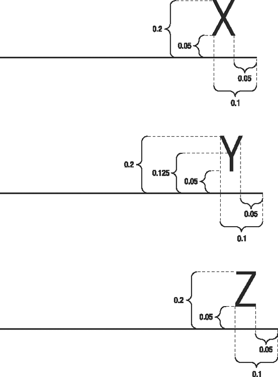
Figure 8-14. A sketch showing the dimensions to create each axis letter
In case you're wondering how we came up with the values presented in Figure 8-14, the answer is easy: trial and error! If you don't like the way the characters look, just adjust the values until you find the desired effect.
private void Create3DAxis()

{

    // Size of 3D axis

    float axisLength = 1f;

    // Number of vertices we'll use

    int vertexCount = 22;


    VertexPositionColor[] vertices = new VertexPositionColor[vertexCount];

    // X axis

    vertices[0] = new VertexPositionColor(

                  new Vector3(-axisLength, 0.0f, 0.0f), Color.White);

    vertices[1] = new VertexPositionColor(

                  new Vector3(axisLength, 0.0f, 0.0f), Color.White);

    // Y axis

    vertices[2] = new VertexPositionColor(

                  new Vector3(0.0f, -axisLength, 0.0f), Color.White);

    vertices[3] = new VertexPositionColor(

                  new Vector3(0.0f, axisLength, 0.0f), Color.White);

    // Z axis

    vertices[4] = new VertexPositionColor(

                  new Vector3(0.0f, 0.0f, -axisLength), Color.White);

    vertices[5] = new VertexPositionColor(

                  new Vector3(0.0f, 0.0f, axisLength), Color.White);


    // "X" letter near X axis

    vertices[6] = new VertexPositionColor(

                  new Vector3(axisLength - 0.1f, 0.05f, 0.0f), Color.White);

    vertices[7] = new VertexPositionColor(

                  new Vector3(axisLength - 0.05f, 0.2f, 0.0f), Color.White);

    vertices[8] = new VertexPositionColor(

                  new Vector3(axisLength - 0.05f, 0.05f, 0.0f), Color.White);

    vertices[9] = new VertexPositionColor(

                  new Vector3(axisLength - 0.1f, 0.2f, 0.0f), Color.White);


    // "Y" letter near Y axis

    vertices[10] = new VertexPositionColor(

                  new Vector3(0.075f, axisLength - 0.125f, 0.0f), Color.White);

    vertices[11] = new VertexPositionColor(

                  new Vector3(0.075f, axisLength - 0.2f, 0.0f), Color.White);

    vertices[12] = new VertexPositionColor(

                  new Vector3(0.075f, axisLength - 0.125f, 0.0f), Color.White);

    vertices[13] = new VertexPositionColor(

                  new Vector3(0.1f, axisLength - 0.05f, 0.0f), Color.White);

    vertices[14] = new VertexPositionColor(

                  new Vector3(0.075f, axisLength - 0.125f, 0.0f), Color.White);

    vertices[15] = new VertexPositionColor(

                  new Vector3(0.05f, axisLength - 0.05f, 0.0f), Color.White);

    // "Z" letter near Z axis

    vertices[16] = new VertexPositionColor(

                  new Vector3(0.0f, 0.05f, axisLength - 0.1f), Color.White);

    vertices[17] = new VertexPositionColor(

                  new Vector3(0.0f, 0.05f, axisLength - 0.05f), Color.White);

    vertices[18] = new VertexPositionColor(

                  new Vector3(0.0f, 0.05f, axisLength - 0.1f), Color.White);

    vertices[19] = new VertexPositionColor(

                  new Vector3(0.0f, 0.2f, axisLength - 0.05f), Color.White);

    vertices[20] = new VertexPositionColor(

                  new Vector3(0.0f, 0.2f, axisLength - 0.1f), Color.White);

    vertices[21] = new VertexPositionColor(

                  new Vector3(0.0f, 0.2f, axisLength - 0.05f), Color.White);


    // Fill the vertex buffer with the vertices

    vertexBuffer = new VertexBuffer(device,

                  vertexCount * VertexPositionColor.SizeInBytes,

                  ResourceUsage.WriteOnly,

                  ResourceManagementMode.Automatic);

    vertexBuffer.SetData<VertexPositionColor>(vertices);

}
You also need to create code in the LoadContent method to call the Create3Daxis, and to free the vertex buffer property in the cls3Daxis class, within the UnloadContent method, as shown in the next code sample.
public void LoadContent()

{

    // Create the 3D axis

    Create3DAxis();

}

public void UnloadContent()

{

    if (vertexBuffer != null)

    {

        vertexBuffer.Dispose();

        vertexBuffer = null;

    }

}
This concludes the code for creating and freeing up (disposing of) the memory resources used for drawing the 3D axis's vertices. However, you can't run the program yet. You still need to code the basic effect that defines how the rendering is done, and to include calls for the cls3Daxis class in the program's main class, Game1.
In the next section, you'll finish the cls3Daxis class, setting the effect properties you need to display the axis.
Coding a Basic Effect and Rendering the 3D Scene
You learned earlier in this chapter that BasicEffect is a class XNA provides to help you create effects for rendering 3D scenes. BasicEffect includes many properties that let you define the camera position, the projection to be used, and the light sources used, for example.
The next code sample shows the complete code for the LoadContent method, including creation and configuration for a simple basic effect, which will suffice for the examples in this chapter. All of the functions and properties used in this code were explained earlier in this chapter; so this might be a good time for you to refer back to the discussions of the projection types and the view and projection matrices.
public void LoadContent()

 {

    // Create the effect that will be used to draw the axis

    effect = new BasicEffect(device, null);


    // Calculate the effect aspect ratio, projection, and view matrix

    float aspectRatio = (float)device.Viewport.Width / device.Viewport.Height;

    effect.View = Matrix.CreateLookAt(new Vector3(0.0f, 2.0f, 2.0f), Vector3.Zero,

                          Vector3.Up);

    effect.Projection = Matrix.CreatePerspectiveFieldOfView(

                       MathHelper.ToRadians(45.0f),

                       aspectRatio, 1.0f, 10.0f);

    effect.LightingEnabled = false;


    // Create the 3D axis

    Create3DAxis();

}
In the CreateLookAt method, you're creating the camera two units up (y axis) from the (0, 0, 0) position, and two units outside the screen boundaries (z-axis negative values are on the screen—visible values—and positive values are outside the screen boundaries); "looking at" the Zero vector (0, 0, 0), and setting the y axis as "up" with Vector3.Up.
You then create a perspective projection matrix, "looking" in a 45-degree angle as the field of view. The rendering happens for objects from 1 to 10 units from the screen (z values from −1 to −10).
Finally, you disable lighting, so the whole scene is rendered with a simple and omnidirectional default light, which does not generate any gradients or shades.
The UnloadContent method also needs to be completed to include the disposal of the effect object, as follows:
public void UnloadContent()

{

    if (vertexBuffer != null)

    {

        vertexBuffer.Dispose();

        vertexBuffer = null;

    }

    if (effect != null)

    {

        effect.Dispose();

        effect = null;

    }

}
Now that you've set up the vertex buffer and the effect, you need to code the Draw method of the cls3Daxis class, which will use the effect to draw the scene, following the blueprint code presented earlier, in the "Lights, Camera . . . Effects!" section.
In the next code fragment, you configure the device to use the vertex format you are using (vertices defined by their position and color). Then, you send the device vertex stream to your vertex buffer, defining the starting point in this stream (start reading from the first vertex) and the size of each vertex element. Once the device is configured, you enter the drawing loop, and call device.DrawPrimitives for every pass of the current effect technique (as explained earlier in this chapter), stating that you are drawing 11 lines (made of 22 vertices).
public void Draw()

{

    // Create a vertex declaration to be used when drawing the vertices

    device.VertexDeclaration = new VertexDeclaration(device,

                                    VertexPositionColor.VertexElements);

    // Set the vertex source

    device.Vertices[0].SetSource(vertexBuffer, 0, VertexPositionColor.SizeInBytes);


   // Draw the 3D axis

    effect.Begin();

    foreach(EffectPass CurrentPass in effect.CurrentTechnique.Passes)

    {

       CurrentPass.Begin();

       // We are drawing 22 vertices, grouped in 11 lines

       device.DrawPrimitives(PrimitiveType.LineList, 0, 11);

       CurrentPass.End();

    }

    effect.End();

}
This code concludes the cls3Daxis class. All you need to do now is call this class's methods from within the Game1 main class, and you'll be able to see the 3D axis.
Coding the Main Program Calls
In the previous section, you created the cls3Daxis class, which provides methods with the same names of the main class of XNA programs: LoadContent, UnloadContent, and Draw.
To use this class, let's now create a new, empty XNA Windows Game project. As you know, the Game1 class is generated for you automatically. You need to define an object of the cls3Daxis class, initialize it, and call the corresponding methods on the Game1 class. The code for the updated methods is as follows:
GraphicsDeviceManager graphics;


// 3D objects

cls3DAxis my3DAxis;


protected override void Initialize()

{

    my3DAxis = new cls3DAxis(graphics.GraphicsDevice);

    base.Initialize();

}


protected override void LoadContent()

{

     // Create the 3D axis

     my3DAxis.LoadGraphicsContent();

}


protected override void UnloadContent()

{

      // Free the resources allocated for 3D drawing

     my3DAxis.UnloadContent();

}


protected override void Draw(GameTime gameTime)

{

    graphics.GraphicsDevice.Clear(Color.CornflowerBlue);

    // Draw the 3D axis

    my3DAxis.Draw();

    base.Draw(gameTime);

}
The result of running this code, shown in Figure 8-15, might not look as you expected. You see only the x and y axes, and this certainly doesn't seem too much like 3D. This is because the camera position is aligned with the z axis, so this axis is hidden behind the y axis, and the letter Z is not drawn, because it's behind the camera.
You could simply adjust the camera position in the cls3Daxis class, but let's do a little better, while exploring a new concept: the world matrix.
The world matrix, as explained when we talked about effects, is a property of the Effect class that contains transformations that are applied to all scene objects when rendering.
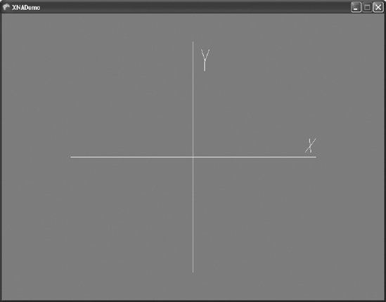
Figure 8-15. The 3D axis
Let's use the world matrix to make this 3D axis drawing spin, so you can see the result of rotating a 3D scene. You can do this in three easy steps:
- Create a new property in the
cls3Daxisclass to store the current world matrix, defaulting to an identity matrix (a matrix that doesn't perform any transformation):
public Matrix worldMatrix = Matrix.Identity; - Include a new line in the
Drawmethod of this class to update the effect'sWorldproperty to this matrix, so the effect receives the updated matrix and is able to use it to transform the axis drawing:
effect.World = worldMatrix; - Include a new line in the
Updatemethod of theGame1class to update thecls3Daxis worldMatrixproperty, incrementing the world rotation angle in every update:
my3DAxis.worldMatrix *= Matrix.CreateRotationY(0.01f) *


                                         Matrix.CreateRotationX(0.01f);
If you run your program now, you will see the nice result of spinning the 3D axis, as shown in Figure 8-16.
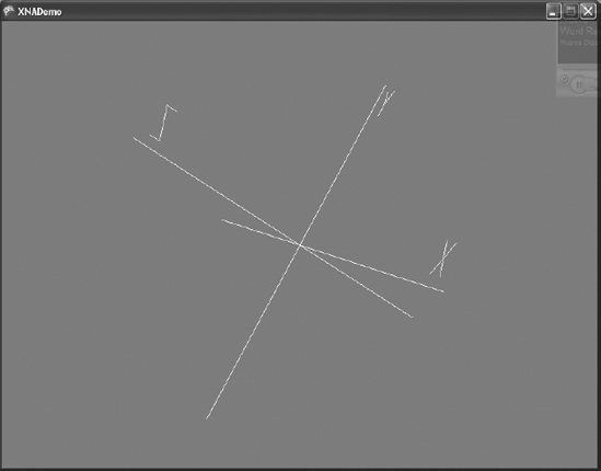
Figure 8-16. The spinning 3D axis
Models and Meshes
Playing around with vertices and drawing primitives is somewhat cool, and it's important to help you understand what's happening behind the scenes when you draw a 3D model. But if you want to create a game with complex 3D objects, this approach would hardly be the best choice.
In Chapter 1, you learned that XNA's Content Pipeline supports many file formats, including 3D object definition X and FBX files. These files store the definition of 3D objects, known as a 3D model or simply a model.
As a simple definition, you can say a model is a hierarchy of meshes, which can be rendered independently. A mesh is a collection of interconnected vertices, along with some rendering information.
XNA provides special classes to manipulate models and meshes: Model and ModelMesh. Using these classes will let you load and manipulate 3D models created in tools like Maya and 3ds Max in your game. This way, you can use much more sophisticated 3D models than you could possibly create inside your program working vertex by vertex. These models can store extra information such as colors, textures, and even animations that can be used by XNA.
To create a program that manipulates models, you must first load a model as new content into your sample program.
To do this, right-click the project in the Content folder in the Solution Explorer window, choose Add ![]() Existing Content, and select an X or FBX file. In this section's example, you'll use the
Existing Content, and select an X or FBX file. In this section's example, you'll use the Cube.X file, a simple file with a cube definition that comes with the DirectX Software Development Kit (SDK), which can be downloaded from the Microsoft site (http://www.microsoft.com/directx).
Tip You can use other models with the same code, but you may need to adjust the view and projection matrices depending on the model; or perform some transformation over the model in order to see it entirely on the game screen. After finishing this chapter's example, try loading and performing the necessary adjustments to use other models, so you'll better understand the view, projection, and transformations matrices before playing around with a full game.
Once the content is in your project, you must declare a model variable to hold the reference to this content, at the Game1 class level:
Model myModel;
In the LoadContent method, you need to include a single line that loads the model:
myModel = Content.Load<Model>("Cube");
Finally, you must include a loop in the Draw method to run through all meshes in the model and draw each one. Although there is only one mesh in this simple model, using this approach makes the code ready to draw complex models:
// Loop through each mesh of the model

foreach (ModelMesh mesh in myModel.Meshes)

{

    // Draw the current mesh

    mesh.Draw();

}
If you run your program now, you will see the mesh already loaded, along with the spinning 3D axis created in the previous section, as shown in Figure 8-17.
The image in Figure 8-17 is not very exciting, because two details prevent the image from appearing like a cube. The camera is upright on one of the cube faces, so all you see is a square. Also, there's no lighting enabled, so every face is illuminated exactly the same way. There's no shading to help you see the difference between one face and another. To work around these problems, you need to rotate the model to a better position (and maybe do some scaling, so it doesn't hide the axis), and apply lights to the model rendering.
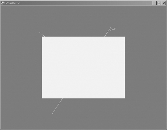
Figure 8-17. The first view of a 3D model (cube)
Remember the BasicEffect class you used in the previous section? With BasicEffect, you can apply transformations to the object (through the World property), set the Projection and the View matrices (which are a must for every effect), and turn on a default light source with little effort, as you saw when we talked about effects earlier in this chapter. You can use the same projection and camera view matrices you used for cls3Daxis. A rotation of 45 degrees in both the x and y axes will turn the cube so you can see three of its faces.
Remember that a model is composed of many meshes. To use the effect to render the 3D object, you must loop through all the meshes to apply the effect to all of them.
Additionally, a mesh has a collection of effects, so it can render different parts of the mesh with different effects—a useful thing for complex meshes. Because you might have many effects for a single mesh, you need to have a second loop, running through all effects of each mesh, to be certain you'll apply the same effect in all mesh parts.
In a simple model such as your cube, you have only one mesh and only one effect on this mesh. Nonetheless, you'll create generic code that allows you to use the same program for more complex models.
The final code with the effect creation and use follows. Place it in the LoadContent method:
// Calculate the aspect ratio for the model

float aspectRatio = (float)graphics.GraphicsDevice.Viewport.Width /

                           graphics.GraphicsDevice.Viewport.Height;


// Configure basic lighting and do a simple rotation for the model

//  (so it can be seen onscreen)

foreach (ModelMesh mesh in myModel.Meshes)

    foreach (BasicEffect effect in mesh.Effects)

    {

        // Rotate and make the model a little smaller (50%)

        effect.World = Matrix.CreateScale(0.5f) *

            Matrix.CreateRotationX(MathHelper.ToRadians(45.0f)) *

            Matrix.CreateRotationY(MathHelper.ToRadians(45.0f));

        // Set the projection matrix for the model

        effect.Projection = Matrix.CreatePerspectiveFieldOfView(

                    MathHelper.ToRadians(45.0f),

                    aspectRatio, 1.0f, 10.0f);

        effect.View = Matrix.CreateLookAt(new Vector3(0.0f, 0.0f, 3.0f),

                  Vector3.Zero, Vector3.Up);

        effect.EnableDefaultLighting();

    }
Figure 8-18 presents the result of running the program with the newly created effect.
Note You don't need to bother to load textures if your model uses them. Model files already include information about the textures they use. Because this information includes the path where the texture files should be located, you just need to know this path and then copy the texture files to the corresponding path. You can find out the texture paths by examining the model files (in a text editor, for example) or by including the model in the project and compiling it. XNA Game Studio presents the Content Pipeline path errors stating where the model looked for the textures.
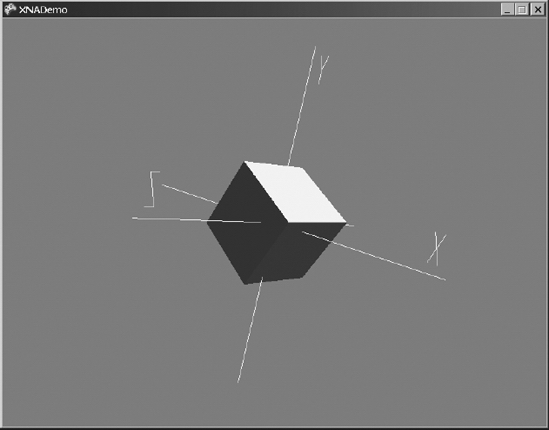
Figure 8-18. The rotated, scaled, and lightened cube
Summary
In this chapter, you learned the basics of 3D graphics programming. Although XNA provides you with many built-in classes and methods that reduce the program's complexity, there are still a lot of concepts to understand.
Be sure you understand the following concepts before you go on to the next chapter:
- What vertices are and what type of information can be used when defining them
- What a vertex buffer is and how to use it
- Why matrices are important, and how to use them to perform transformations in 3D objects
- What the projection matrix is, which types of projections XNA supports, and how to use them
- What the view matrix is and how you create it in XNA
- What the world matrix is, and how to use it to perform operations in all 3D scenes
- What models and meshes are, and how to load and render them in XNA
In the next chapters, you'll create a complete 3D game, so you'll be able to better exercise and explore these concepts.