
CHAPTER 9
Rendering Pipeline, Shaders, and Effects
In this chapter, you'll learn some of the concepts related to the rendering pipeline, shaders, and effects. The rendering pipeline is responsible for rendering a 3D scene into a 2D image, which can then be drawn on the screen. You can use shaders to program some stages of the rendering pipeline, and use effects to describe a combination of shaders and configurations for the fixed stages of the rendering pipeline. This flexibility allows you to create custom visual effects, improving the visual aspect of the final image.
Rendering Pipeline
To visualize a 3D scene on the screen, the scene must be transformed into a 2D image. The process that transforms a 3D scene into an image is called rendering. Figure 9-1 shows a high-level diagram of the rendering pipeline used by XNA.
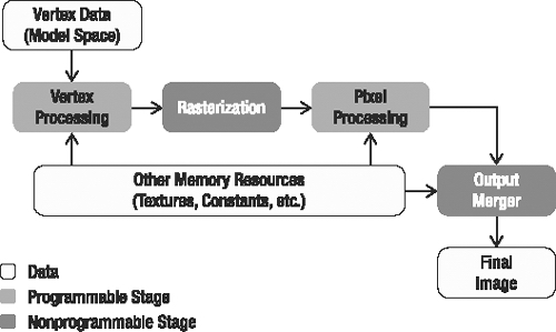
Figure 9-1. XNA rendering pipeline
An object in a 3D scene is described through its mesh, which is the collection of its vertices (and indices, if applicable). The vertices in a mesh can have many different attributes, such as position, color, normal, and texture coordinate, as explained in Chapter 8.
As illustrated in Figure 9-1, at the beginning of the rendering process, the vertices of the object's mesh are sent to the rendering pipeline, where they go through the stages of vertex processing, rasterization, and pixel processing. At the end of this process, many pixels are generated, ready to be stored in the scene's final image. Since many triangles of one object can compete for the same pixels on the screen, the last stage in the rendering pipeline—the output merger—decides which pixels are closest to the camera. The output merger stores those pixels in the final image and decides which pixels are to be discarded. This decision is based on the distance between the camera and the object, so only the closest objects are displayed, but this decision can also be influenced by transparency information.
In the old versions of the DirectX and OpenGL application programming interfaces (APIs), all the stages of the rendering pipeline were fixed (preprogrammed). This meant that a fixed set of effects was available to game programmers. This forced all games to use the same rendering processes, allowing them to change only a few predefined parameters. The result was the release of many game titles with similar graphics.
From DirectX 8.1 onward, it became possible to program some of the stages of the rendering pipeline through the creation of small programs called shaders. Shaders allow you to define which data is input and output from each programmable stage of the graphics processing unit (GPU), and, more important, the processing that is happening within each stage. Using shaders, you can create many new effects for games that weren't possible using the fixed pipeline.
In XNA, you use shaders to render any object to the screen. To ease game development without needing to program your own shaders, XNA provides some helper classes that contain a basic set of shaders and effects. For example, you can use the SpriteBatch class to draw 2D sprites, and the BasicEffect class to draw 3D models. These two classes use shaders in a way that's transparent to you. As their names imply, these classes support only basic rendering. The SpriteBatch class will render your images just as they've been saved on disk, but don't ask it to add any spotlights, reflective objects, or effects like rippling in your images. The BasicEffect class can render your 3D world using only basic lighting. If you want to program some fancier effects, you can create your own shaders.
Shaders
Shaders are small programs that execute inside the GPU and define how the data received from your XNA program is processed in the programmable stages of the rendering pipeline. Shaders are most commonly written in the High Level Shading Language (HLSL).
Two shaders are generally applied: a vertex shader and a pixel shader. The rasterization stage is executed between the vertex shader and the pixel shader.
Vertex Shader
The shader used in the vertex processing stage, shown in Figure 9-1, is called the vertex shader. The basic task of the vertex shader is to read the original coordinates of the vertices from your XNA program, transform them to 2D screen coordinates, and present them to the next stage. Additionally, along with manipulating coordinates, you can also choose to process other attributes of each vertex, such as its color, normal, and so on.
Vertex shaders allow you to execute many tasks, such as solids deforming, skeletal animation, and particle motion.
Rasterization
In the rasterization stage, your GPU determines which screen pixels each triangle occupies. All of these pixels are sent to the pixel shader (discussed next), allowing you to do one final phase of processing.
Figure 9-2 illustrates a rasterized triangle, which generates many pixels. Note especially that the vertex attributes are linearly interpolated between all the generated pixels.
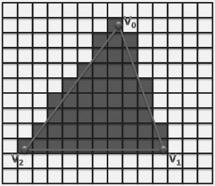
Figure 9-2. Triangle rasterization. The gray quads represent the pixels generated.
Pixel Shader
The main task of the pixel shader is to receive a pixel as input, calculate the final color of the pixel, and pass it on to the output merger. Each pixel can provide the pixel shader with a wide variety of data, generated by your vertex shader and linearly interpolated by the rasterizer. This allows your pixel shader to adjust the color of the pixel according to the lighting conditions, add reflections, perform bump mapping, and more. You can also use a pixel shader to apply postprocessing effects over an entire rendered scene, such as brightness, contrast and color enhancements, saturation, and blur.
Additionally, the pixel shader can change the depth of the pixel. This depth is used by the output merger to decide which pixels are drawn and which are not drawn. By default, this depth indicates how far the originating triangle is from the camera. However, if you want to influence the decision of the output merger, you can specify this value yourself.
High-Level Shading Language
XNA natively supports shader programming through Microsoft's HLSL. HLSL has a few built-in functions, which include math operations, texture access, and flow control. The types of data that HLSL supports are similar to those used in the C language, with the exception of vectors, matrices, and samplers.
HLSL Data Types
HLSL supports many different data types, including scalars, vectors, and matrices. Table 9-1 shows the scalar data types present in the language. Note that it is possible to create vectors and matrices for all the scalar types present in the language, such as float2, float4, bool3×3, double2×2, and so on.
| Type | Value |
bool |
true or false |
int |
32-bit signed integer |
half |
16-bit floating point |
float |
32-bit floating point |
double |
64-bit floating point |
Another data type present in HLSL is the sampler type, which is used to sample data from textures. Different sampler types, such as sampler1D, sampler2D, and sampler3D, are used to sample 1D, 2D, and 3D textures, respectively. Associated with the sampler type are a few states, which specify the texture to be sampled, the type of filtering used, and how the texture is addressed (wrapped).
Samplers should be defined at the top of your HLSL code file. Here is an example of a sampler for a 2D texture:
// Declares the input texture

texture skyTexture;


// Declares the sampler used to sample the skyTexture

sampler2D skySampler = sampler_state

{

    Texture = skyTexture;


    MinFilter = Linear;

    MagFilter = Linear;

    MipFilter = Linear;

    AddressU = Wrap;

    AddressV = Wrap;

    AddressW = Wrap;

}
The texture state represents the texture to be sampled, which can be read only through the use of a sampler. MinFilter, MagFilter, and MipFilter are the filtering states, and AddressU, AddressV, and AddressW are the addressing states.
Note The documentation for the DirectX SDK includes a complete reference for HLSL. You can access this reference at http://msdn2.microsoft.com/en-us/library/bb509638.aspx.
Uniform and Varying Inputs
HLSL has two types of input data types:
- Uniform input data:
This is the data that is constant for all vertices/pixels in a shader during the processing of its entire input data. For example, during the rendering of a tree, its texture, the world matrix, and lighting conditions are constant. The uniform input data in a shader is set from within your XNA application.
- Varying input data:
This is the data that is changed in each execution of a shader. For example, during the rendering of a tree, the vertex shader needs to process all vertices of the tree. This means that the information carried inside the vertex is changed for each cycle of the vertex shader. Unlike with the uniform input data, you declare the varying input data using semantics, as discussed in the next section.
Semantics
Semantics are predefined words that HLSL uses to map input and output data to variable names. For example, each vertex of your 3D objects might contain one float4 containing the 3D position, and another float4 containing two texture coordinates. How is your vertex shader supposed to know which of them to use as the position?
The solution is to add the POSITION0 semantic in the vertices' processing stage to map the position attribute of each vertex to a varying variable, as follows:
float4 vertexPosition : POSITION0;
The semantics are required in all varying input data (received from the application or passed between the rendering stages). For example, all the data output from the vertex shader that will be used in the pixel shader must be associated with a semantic. You will see some examples of using semantics in the "Creating a Simple Shader" section later in this chapter.
Semantics are not case-sensitive and are specified after the variables' names using a colon (:). Tables 9-2 and 9-3 show some vertex shader semantics.
Table 9-2. Input Vertex Shader Semantics
| Input | Description | Type |
POSITION[n] |
Vertex position in object space | float4 |
COLOR[n] |
Diffuse and specular color | float4 |
NORMAL[n] |
Normal vector | float4 |
TEXCOORD[n] |
Texture coordinate | float4 |
TANGENT[n] |
Tangent vector | float4 |
BINORMAL[n] |
Binormal vector | float4 |
BLENDINDICES[n] |
Bones blend indices | int4 |
BLENDWEIGHT[n] |
Bones blend weight | float4 |
Table 9-3. Output Vertex Shader Semantics
| Output | Description | Type |
POSITION[n] |
Position of a vertex in homogenous space | float4(X, Y, Z, W) |
COLOR[n] |
Diffuse or specular color | float4 |
TEXCOORD[n] |
Texture coordinates | float4 |
FOG |
Vertex fog | float |
You use the input vertex shader semantics for varying data received by the vertex shader. Some commonly used semantics are POSITION, COLOR, NORMAL, and TEXTURE. You use the TANGENT and BINORMAL semantics if the vertex has tangent or binormal vectors, which you'll need when you want to do some bump mapping in your effect. You use the BLENDINDICES and BLENDWEIGHT semantics when the vertices are linked to bones. Bones are used to deform the vertices of a mesh (as explained in Chapter 12).
The POSITION semantic is the only required output of the vertex shader. If you want to pass other data from the vertex shader to the pixel shader, TEXCOORD[n] should be used.
The [n] is an optional integer that defines the number of the resource to be used. For example, if a model has three textures, the [n] of its TEXCOORD semantic can be 0, 1, or 2; so, TEXCOORD0, TEXCOORD1, and TEXCOORD2 are valid input semantics for the vertex shader. Table 9-4 shows some pixel shader semantics.
Table 9-4. Pixel Shader Semantics
| Input | Description | Type |
COLOR[n] |
Diffuse or specular color | float4 |
TEXCOORD[n] |
Texture coordinates | float4 |
COLOR[n] |
Output color | float4 |
DEPTH[n] |
Output depth | float |
Because the pixel shader is executed after the rasterization stage, the available input semantics are the pixel color and some texture coordinates. The texture coordinates address the texture positions that are mapped into the current pixel, and these coordinates can be used to transfer data from your vertex shader to your pixel shader.
The final data output from the pixel shader is the pixel color and depth, where the output of the pixel color is obligatory, and the output of the pixel depth is optional.
Functions
HLSL allows the creation of functions with syntax like the C language, where each function has a declaration and a body. The function declaration contains the function name and return type, and might have a list of parameters. Also, the return type of a function may have a semantic associated with it.
The following is a function used as the entry point for the pixel shader:
float4 simplePS(float4 inputColor : COLOR0) : COLOR0

{

    return inputColor * 0.5f;

}
Because the simplePS function is used as the entry point to the pixel shader, its parameters must have a semantic associated. In this case, the simplePS function scales the received color parameter by a factor of 0.5 and returns it as the final pixel color. Note that the parameters of the function can have other modifiers, such as in, out, and inout, which are used to define input, output, and input/output parameters.
We'll demonstrate how to define the functions that will be used as the entry point for the vertex and pixel shaders in the "Techniques, Passes, and Effects" section later in this chapter.
A small set of intrinsic functions are built into HLSL. These include math operations, texture access, and flow control. These functions don't necessarily map directly to the GPU assembly instructions. In fact, many of these functions are mapped to a combination of GPU assembly instructions, and they're likely to provide the best implementation for their task. Table 9-5 lists commonly used HLSL functions.
Table 9-5. Commonly Used HLSL Functions
Creating a Simple Shader
In this section, you'll put together what you've learned, and create your first shader using HLSL. As a good habit, you should start by declaring the uniform and varying variables:
// Matrix received from the application - Uniform

// (World * View * Projection)

float4×4 matWVP : WorldViewProjection;


// Struct used for the input vertex - Varying

struct vertexInput

{

    float4 position : POSITION0;

};


// Struct used to pass the VS output to the PS input - Varying

struct vertexOutput

{

    float4 hposition : POSITION;

    float3 color : COLOR0;


};
Your shader will expect the matWVP matrix to be set by your XNA application. This world-view-projection matrix is created by the camera, and it should be set by your XNA program. It is needed when your vertex shader transforms 3D positions to 2D screen coordinates.
You use the vertexInput struct to define the information that the vertex shader can expect. As you can see, this vertex shader will be capable of processing all vertices that contain position data.
You use the vertexOutput struct to define the kind of data that is passed from the vertex shader to the rasterizer, and after linear interpolation, to the pixel shader. Your vertex shader will generate the mandatory position, as well as a color.
An important note here is that the vertex position output by the vertex shader is not accessible by the pixel shader. This 2D screen position is required by the rasterizer, so a good way to remember that you cannot access it from your pixel shader is to keep in mind that it is "consumed" by the rasterizer. If you need this 2D screen position in your pixel shader, you should pass it as an additional TEXCOORDINATE[n] semantic.
Next, declare the vertex shader itself:
// Vertex shader code

pixelInput SimpleVS(vertexInput IN)

{

    pixelInput OUT;


    // Transform the vertex position

    OUT.hposition = mul(IN.position, matWVP);

    OUT.color = float3(1.0f, 1.0f, 0.0f);

    return OUT;

}
The vertex shader is called on each vertex rendered by your XNA application. This vertex is accepted by your shader as a vertexInput object and processed into a pixelInput object. In the SimpleVS function, you calculate the output 2D screen position by transforming (multiplying) it by the matWVP matrix. The output vertex color is set to yellow, RGB (1, 1, 0).
Next, you define the pixel shader:
// Pixel shader code

float4 SimplePS(pixelInput IN) : COLOR0

{

    return float4(IN.color.rgb, 1.0f);

}
This pixel shader simply returns the color received from the vertex processing stage. This color will be used as the final pixel color.
Great! Now you have defined a vertex shader and a pixel shader. In your XNA application, however, you don't specify separately which vertex shader and pixel shader should be used to render your triangles to the screen. Instead, you specify which technique to use.
Techniques, Passes, and Effects
In its most basic form, a technique is nothing more than the combination of a vertex shader and a pixel shader. The following is a technique that uses the vertex shader and pixel shader you just defined:
technique basicTechnique

{

    pass p0

    {

        VertexShader = compile vs_2_0 SimpleVS();

        PixelShader = compile ps_2_0 SimplePS();

    }

}
A technique also defines for which shader model the shader should compile. In this case, you're using the shader model 2.0 for both shaders. Higher models allow more complex shaders and more functionality, but require that the GPU support them.
As you can see, both shaders are encapsulated in what is called a pass. One pass reads in all vertices that should be drawn with the technique, processes them, processes the resulting pixels, and renders these pixels to the backbuffer, where they are waiting to be presented to the screen after all of the pixels have been processed. For some techniques, you may want to do this process twice during the same frame for all vertices. Therefore, such techniques will have two passes, each with a vertex shader and pixel shader.
For some more advanced effects, you'll want to use multiple techniques. You'll use a first technique to transform your scene into an intermediate image, which can be used by another technique as input.
The combination of all shaders and techniques used is called an effect. A simple effect will contain a vertex shader, a pixel shader, and a technique. A more advanced effect (such as shadow mapping or deferred rendering) will contain several of each.
The differentiation between effect, techniques, and shaders facilitates the shaders' programming, making it possible to reuse shader code in different techniques, and also to create different techniques targeting low-end and high-end GPUs.
Since you will usually keep all shaders and techniques corresponding to the same effect in one file, XNA calls each HLSL code file an effect. This allows XNA to treat effects as game assets, just like models and textures. All the effects are processed through the XNA Content Pipeline, generating manageable objects that the content manager can load at runtime.
Effect Class
At this point, you have created and coded your first complete effect in an .fx file. This means you can close the .fx file and move to your XNA project. The next step is to load this effect into your XNA program, so you can use it to render something to the screen. In your XNA program, the effect should be loaded into an object of the Effect class (just as an image would be loaded into an object of the Texture2D class). This Effect class allows you to configure the effect's uniform parameters, select the current effect technique, and use the effect for rendering. The following code illustrates how to load and configure an effect with XNA:
// XNA Effect object

Effect effect;


// Load the effect

effect = content.Load<Effect>("/effects/simpleEffect");


// Set the technique

effect.CurrentTechnique = lightEffect.Techniques["basicTechnique"];


// Configure uniform effect parameters

effect.Parameters["matWVP "].SetValue(worldViewProjectionMatrix);
This code initially loads the simpleEffect effect from the HLSL code file using the content manager's content.Load method. Then it defines which technique of the effect will be used; in this case, the basicTechnique technique you defined earlier. Finally, it sets the only uniform effect parameter defined in the HLSL code file: matWVP.
The following code shows how to draw an object using the loaded effect:
// First begin the effect

effect.Begin();


// Remember that the effect can have many passes

foreach (EffectPass pass in effect.CurrentTechnique.Passes)

{

    pass.Begin();

    // PUT YOUR DRAWING CODE HERE

    pass.End();

}


// Finally, end the effect

effect.End();
To draw a 3D object, you first need to begin the effect you want to use to render it, and then go through all the passes of the selected technique. For each pass, you need to begin the pass, draw the object, and end the pass. Finally, you need to end the effect. The effect pass is represented by XNA's EffectPass class, while its techniques are accessed through the CurrentTechnique property of the Effect class. If you want to change an effect parameter after the beginning of a pass, you need to call the CommitChanges method of the Effect class to update the changes.
The steps previously shown are necessary only if you're going to draw a model by yourself. When you load a 3D model from disk, the model comes with its effects stored inside its ModelMesh objects.
Effect Helper Classes
When an effect is loaded through the content manager, you don't know what parameters or techniques it has. Also, to modify an effect parameter, you must first query this parameter inside the effect, and then modify it. So, you might configure an effect parameter called lightPosition like this:
effect.Parameters["lightPosition"].SetValue(new Vector3(0.0f, 40.0f, 0.0f));
In this code, when you alter the value of the lightPosition parameter, a query is made inside the effect for the lightPosition parameter. This presents two problems: the computational overhead required to query for this parameter and the possibility of a query for an invalid parameter. Using helper classes, you can avoid these problems.
To ease the management of custom-created effects, you can create a unique helper class for each effect. Each effect helper class will store a reference for all the effect parameters, avoiding the overhead of constant querying for the parameters. The following code shows how to store a reference for the effect parameter and change its value:
EffectParameter param1 = effect.Parameters["lightPosition"];


// Render loop

{

    param1.SetValue(new Vector3(0.0f, 40.0f, 0.0f));

    // Draw model

    ... ...

}
Materials
Materials are classes that you should create to store the parameters used to configure an effect. For example, you can render two surfaces using an effect that applies a texture to each of them. In this case, the material of each surface is its texture, which you use to configure the effect used to render the surfaces. So, if the two surfaces share the same material, you could set the desired effect and the desired material, and render both surfaces in sequence by avoiding changing the effect that is currently set or its parameters.
The following are the two basic material classes that you'll create:
LightMaterial: This class will store the surface properties used for lighting (diffuse color, specular color, and specular power).TextureMaterial: This class will stores a texture map and tile used to apply a texture to a surface.
You could use these two basic material classes to create more complex types of materials, such as a multitexturing material.
Here is the complete code for the LightMaterial class:
public class LightMaterial

{

    // Material properties - diffuse and specular color

    Vector3 diffuseColor;

    Vector3 specularColor;

    // Specular power (Shininess)

    float specularPower;


    // Properties

    public Vector3 DiffuseColor

    {

        get { return diffuseColor; }

        set { diffuseColor = value; }

    }

    public Vector3 SpecularColor

    {

        get { return specularColor; }

        set { specularColor = value; }

    }


    public float SpecularPower

    {

        get { return specularPower; }

        set { specularPower = value; }

    }

    public LightMaterial (Vector3 diffuseColor, Vector3 specularColor,

        float specularPower)

    {

        this.diffuseColor = diffuseColor;

        this.specularColor = specularColor;

        this.specularPower = specularPower;

    }

}
You store the light's diffuse and specular colors as an XNA Vector3 in the diffuseColor and specularColor attributes of the LightMaterial class, respectively. You store the light's specular power (or shininess) as a float value, in the specularPower attribute of the class. Note that the (X, Y, Z) components of the color vector represent a color in the RGB format. You also need to create properties to set and retrieve the light's diffuse color, specular color, and specular power.
Here is the complete code for the TextureMaterial class:
public class TextureMaterial

{

    // Texture

    Texture2D texture;

    // Texture UV tile

    Vector2 uvTile;


    // Properties

    public Texture2D Texture

    {

        get { return texture; }

        set { texture = value; }

    }

    public Vector2 UVTile

    {

        get { return uvTile; }

        set { uvTile = value; }

    }


    public TextureMaterial(Texture2D texture, Vector2 uvTile)

    {

        this.texture = texture;

        this.uvTile = uvTile;

    }

}
You store the texture as an XNA Texture2D in the texture attribute of the TextureMaterial class. The texture UV tile, which is used for bump mapping, is stored as an XNA Vector2 in the uvTile attribute of the class. As in the LightMaterial class, you need to create properties to set and retrieve the texture and its UV tile.
Shader Authoring Tools
During shader development, you constantly need to modify your shader, adjust its parameters, and test it using different assets (models, textures, and so on). This process can be slow and tiring if you need to recompile and execute your game every time you change something in one of its shaders. To help you during shader development, you can use a shader authoring tool.
One of the best tools available for shader authoring is NVIDIA's FX Composer, available from the NVIDIA developer web site (http://developer.nvidia.com). FX Composer, is a cross-platform integrated development environment (IDE) for shader authoring. It supports a few shader languages, including HLSL, and many types of asset formats, such as COLLADA, FBX, X, 3DS, and OBJ. Using FX Composer, you can watch the results of your shader in real time while you're developing and modifying it. Other features of FX Composer include scene management and shader performance analysis.
Summary
In this chapter, you learned about the rendering pipeline, its stages, and how to use them to process the description of a 3D scene and output a 2D image.
You also learned how to create shaders to program the programmable stages of the GPU, and the relationship between shaders, techniques, and effects.
Finally, you learned how to load, configure, and use effects with XNA. After the Content Pipeline processes the effects, you can easily load and use them to render your 3D objects.
Now that you've reviewed some basic concepts of shaders and effects, you can start drawing some 3D models. In the following chapters, you'll create more complex effects to render 3D models. For each effect, you'll also create a new helper effect class that will use the created material classes.