
CHAPTER 11
Generating a Terrain
In this chapter, you'll learn how to create a 3D terrain for your game. Terrains are an excellent way to represent outdoor environments. They can be generated at random or stored in and loaded from a 2D grayscale image, called a height map.
The chapter explains how you can create a terrain based on a height map. In each grid point or vertex of your terrain, you will also provide extra information such as the normal and tangent. This information will be needed by your effect, where you implement correct lighting on your terrain and enhance its appearance.
To give a photorealistic look to the terrain, you're also going to implement multitexturing in your HLSL effect (HLSL effects were introduced in Chapter 9). To top off your HLSL effect, you'll apply the more advanced normal mapping technique to it, which increases the visual detail of the terrain without adding extra triangles.
At the end of the chapter, you'll create some auxiliary methods for the terrain: one used to query the height of a position over the terrain, and another to check the collision between a ray and the terrain. Both will be very useful for creating a terrain-based game, as you'll do in Chapter 13.
Height Maps
Height maps are 2D maps used to store the height of a terrain. They're usually stored in grayscale images, where each point of the image stores the terrain's height at that position as a grayscale value. The more white a pixel is, the higher the corresponding point in the terrain should be. Figure 11-1 shows a sample height map.
To construct a terrain from a height map, you first need to build a vertex grid with the same dimensions as the height map, and then use the height value of each point (pixel) on the height map as the height (y coordinate) of a vertex on the vertex grid.
Besides its position, each vertex on the grid should contain other attributes needed in your effects, such as the normal of that point and the texture coordinates. Figure 11-2 illustrates a vertex grid with 6 × 6 vertices created over the world plane x,z, where the y height axis appears to be protruding from the page.
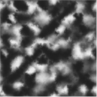
Figure 11-1. An example of a height map
How Height Maps Work
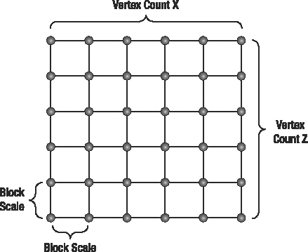
Figure 11-2. A 6 × 6 vertex grid created over the x,z plane
In a vertex grid, the distance between all vertically and horizontally neighboring vertices should be the same. This distance is represented by the block scale, as shown in Figure 11-2. A small distance between the vertices allows smooth transitions between the vertices' heights over the vertex grid, but you'll need a lot of vertices for a large terrain. A big distance between the vertices allows for larger terrains, but can yield sharp transitions between the vertices' heights. For a height map containing 256 × 256 pixels, if the distance between each pair of vertices (vertically and horizontally) is 1 meter, the total size of the generated terrain will be 255 × 255 meters.
As the terrain's height map is usually stored in 8-bit images, its height values vary between 0 and 255, where 0 (black color) represents the lowest possible height for a vertex and 255 (white color) represents the highest possible height. You can lower or raise this interval using a scale factor, which you use to multiply the height values stored in the height map by, adjusting its range. Figure 11-3 shows a 3D terrain built from the height map of Figure 11-1, rendered in wireframe (top) and solid (bottom).
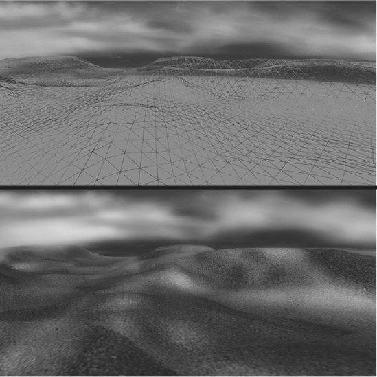
Figure 11-3. Terrain generated from the height map in Figure 11-1 in wireframe (top) and solid rendering (bottom)
Note that the rendered terrain in Figure 11-3 is shown correctly illuminated and textured. To achieve this effect, you need to store the normal and the texture coordinate for each vertex, as explained in this chapter.
Generating a Height Map
You can build or obtain height maps in different ways. You can find many different kinds of height maps on the Internet, including height maps of real places (such as cities or even landscapes from other planets). Because height maps are grayscale images, you can use any image editor tool to build or edit your own height maps. However, one of the simplest and fastest ways to build height maps is through the use of procedural-generation tools.
Note All image formats supported by the XNA Content Pipeline are valid formats for height maps. This means that you can use almost any image you find as height map, and edit it using the program of your choice.
One such procedural-generation tool is Terragen (http://www.planetside.co.uk/terragen/). Terragen allows the generation of a height map from various user-defined parameters, such as terrain size, realism, smoothing, glaciation, and canyonism. Terragen is free to use for noncommercial applications. An artist could refine the height map generated by Terragen at a later time.
Another tool you can use to create height maps is EarthSculptor (http://www.earthsculptor.com/). EarthSculptor has some internal tools for 3D modeling of terrains, and it allows you to save the terrain model as a height map image, ready to be imported into your XNA project.
Creating the Terrain Class
In this section, you'll create the class to handle the terrain, named Terrain, where you'll initially create methods to load a height map, generate the corresponding 3D mesh, and draw it.
Loading the Terrain Height Map
You start by creating the Load method of your Terrain class, which should load a height map from disk and create the corresponding VertexBuffer and IndexBuffer. As the height map is stored as an image file, you can import it into XNA as you would import any other image: using the Content Pipeline.
.Texture2D heightMapTexture = Content.Load<Texture2D>(heightMapFileName);

int heightMapSize = heightMapTexture.Width*heightMapTexture.Height;

heightMap = new Color[heightMapSize];

heightMapTexture.GetData<Color>(heightMap);


this.vertexCountX = heightMapTexture.Width;

this.vertexCountZ = heightMapTexture.Height;
In this code, you load the image into a Texture2D object, the same way you would load any other image into your XNA project. Next, you find how many pixels the image contains, which you need to create an array capable of storing that many Color objects in the next line. Finally, you transfer all data from the image into your heightMap array, which you can easily access when you define the coordinates for your vertex grid.
You also store the size of the image, as you'll use this information to define the size of your vertex grid. vertexCountX defines the number of vertices per row (over the x axis) of the vertex grid, and vertexCountZ defines the number of vertices per column (over the z axis).
You store the height map colors in the heightMap variable, which is an attribute of your Terrain class. Note that you'll also need the height map data to be able to query the height of a position over the terrain, which you'll do at the end of this chapter.
Now that you have the height map data ready, you can generate the terrain's mesh. You create the GenerateTerrainMesh method, as described in the next section, to generate the terrain's mesh, which is composed of indices and vertices. The GenerateTerrainMesh method must be called after the height map has been loaded.
// Generate terrain mesh

GenerateTerrainMesh();
You can also store the transformations that are currently set on the terrain (translate, rotate, and scale) inside the Terrain class, using the Transformation class you created in Chapter 10. To do that, add a new attribute of type Transformation to the Terrain class, and name it transformation. Then, when the terrain's height map is loaded, you must instantiate a new Transformation:
transformation = new Transformation();
Next, you should load a custom effect for the terrain and encapsulate it in a TerrainEffect object. As described in Chapter 9, you should create a helper class for each effect that you create, to make it easier to manage and modify the effect parameters. The TerrainMaterial class is another class you create to configure the terrain effect:
// Load effect

effect = new TerrainEffect(

    Game.Content.Load<Effect>(TerrainEffect.EFFECT_FILENAME));

terrainMaterial = new TerrainMaterial();
The custom effect that we'll show you for the terrain provides a more realistic rendering using multitexturing and normal mapping, as discussed later in this chapter.
Finally, the VertexDeclaration needs to be declared once at startup, so that you're ready to tell your graphics card what kind of data is contained in your vertices:
// Load vertex declaration once

this.vertexDeclaration = new VertexDeclaration(GraphicsDevice,

     VertexPositionNormalTangentBinormalTexture.VertexElements);
Following is the complete code for the Load method of the Terrain class:
public void Load(ContentManager Content, string heightMapFileName,

                  float blockScale, float heightScale)

{

    if (!isInitialized)

        Initialize();

    // Load heightMap file

    Texture2D heightMapTexture = Content.Load<Texture2D>(heightMapFileName);

    int heightMapSize = heightMapTexture.Width*heightMapTexture.Height;

    heightMap = new Color[heightMapSize];

    heightMapTexture.GetData<Color>(heightMap);


    this.vertexCountX = heightMapTexture.Width;

    this.vertexCountZ = heightMapTexture.Height;

    this.blockScale = blockScale;

    this.heightScale = heightScale;


    // Generate terrain mesh

    GenerateTerrainMesh();

    transformation = new Transformation();


    // Load effect

    effect = new TerrainEffect(

        Game.Content.Load<Effect>(TerrainEffect.EFFECT_FILENAME));

    terrainMaterial = new TerrainMaterial();


    // Load vertex declaration once

    this.vertexDeclaration = new VertexDeclaration(GraphicsDevice,

      VertexPositionNormalTangentBinormalTexture.VertexElements);


}
The Load method receives as parameters the height map's file name; the block scale, which represents the distance between the vertices; and a height scale value, used later to scale the height of the terrain. The last two parameters are stored in the Terrain class, in the attributes blockScale and heightScale, respectively.
Generating the Terrain's Mesh
The Load method shown in the previous section calls the GenerateTerrainMesh method, which still needs to be defined. To generate the terrain's mesh, you need to generate its vertices and indices. Each vertex of the grid contains a 3D coordinate and stores some attributes needed for rendering, such as the normal and the texture coordinate. The indices define the order in which the vertices should be combined to generate triangles. You should generate the mesh's indices prior to its vertices, because you can calculate some of the vertex attributes, such as the vertex normal, only if you know which vertices are used by which triangles.
Creating a Custom Vertex Format
XNA comes with a few predefined vertex structures (such as VertexPositionColor and VertexPositionColorTexture), but even the most complex vertex structure (VertexPositionNormalTexture) can store only a 3D position, a normal, and a texture coordinate. For your terrain, each vertex will need to store more information: a 3D position, normal, tangent, and texture coordinate (see the "An Overview of Terrain Techniques" section later in the chapter for an explanation of why you need all of these). This means that you need to define a custom vertex structure, capable of storing all this data for each vertex as it's transferred to your graphics card. The code for this custom vertex structure follows:
public struct VertexPositionNormalTangentBinormalTexture

{

    public Vector3 Position;

    public Vector3 Normal;

    public Vector2 TextureCoordinate;

    public Vector3 Tangent;

    public Vector3 Binormal;


    public static readonly VertexElement[] VertexElements = new VertexElement[]

    {

        new VertexElement(0, 0, VertexElementFormat.Vector3,

         VertexElementMethod.Default, VertexElementUsage.Position, 0),

        new VertexElement(0, 12, VertexElementFormat.Vector3,

          VertexElementMethod.Default, VertexElementUsage.Normal, 0),

        new VertexElement(0, 24, VertexElementFormat.Vector2,

          VertexElementMethod.Default,VertexElementUsage.TextureCoordinate, 0),

        new VertexElement(0, 32, VertexElementFormat.Vector3,

          VertexElementMethod.Default, VertexElementUsage.Tangent, 0),

        new VertexElement(0, 44, VertexElementFormat.Vector3,

          VertexElementMethod.Default, VertexElementUsage.Binormal, 0)

    };

    public static readonly int SizeInBytes = sizeof(float) * (3 + 3 + 2 + 3 + 3);

}
The VertexPositionNormalTangentBinormalTexture structure has all the attributes that you need for a vertex of your terrain: position, texture coordinate, normal, tangent, and binormal. This structure also declares a VertexElement array that contains the format of the vertex data, which has the type, size, and location of each element in the vertex stream. This is required, so the GPU on your graphics card knows where to find each attribute in the data stream.
Creating the GenerateTerrainMesh Method
You'll create two separate methods to generate the mesh's indices and vertices, respectively named GenerateTerrainIndices and GenerateTerrainVertices. You'll call these methods from the GenerateTerrainMesh method (which you will create now) to generate the mesh's vertices and indices. Then you'll create a vertex buffer (VertexBuffer) to store the mesh's vertices and an index buffer (IndexBuffer) to store the mesh's indices. Use the following code for the GenerateTerrain method:
private void GenerateTerrainMesh()

{

    numVertices = vertexCountX * vertexCountZ;

    numTriangles = (vertexCountX - 1) * (vertexCountZ - 1) * 2;

    // You must generate the terrain indices first

    int[] indices = GenerateTerrainIndices();


    // Then generate terrain vertices

    VertexPositionNormalTangentBinormal[] vertices =

        GenerateTerrainVertices(indices);


    // Create a vertex buffer to hold all the vertices

    vb = new VertexBuffer(GraphicsDevice, numVertices *

        VertexPositionNormalTangentBinormal.SizeInBytes, BufferUsage.WriteOnly);

    vb.SetData<VertexPositionNormalTangentBinormal>(vertices);


    // Create an index buffer to hold all the indices

    ib = new IndexBuffer(GraphicsDevice, numTriangles * 3 * sizeof(int),

        BufferUsage.WriteOnly, IndexElementSize.ThirtyTwoBits);

    ib.SetData<int>(indices);

}
Generating the Mesh's Indices
In this section, you'll create the GenerateTerrainIndices method to generate the indices of the terrain's mesh. The mesh's indices define in which order the vertices should be combined to generate triangles. Figure 11-4 shows the indices of the vertices in a grid and how they are combined to form triangles.
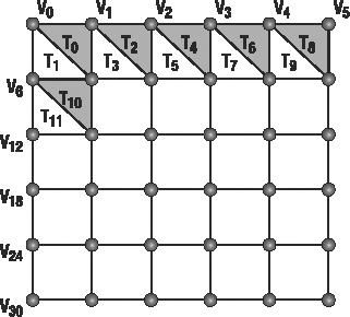
Figure 11-4. Indexing grid vertices to create triangles
Each quad in the terrain has two triangles: a gray triangle and a white triangle. In the first quad of the grid, the gray triangle is constructed from vertices 0, 1, and 7, while the white triangle uses vertices 0, 7, and 6.
Note that the order of the triangle's vertices is important. It should be clockwise relative to the viewer/camera, because the XNA rendering pipeline assumes that counterclockwise rendered triangles are facing backward, and culls them (removes them from the 2D screen output) by default.
Notice that there is a mathematical pattern between the indices used to create the triangles. The indices of the first and second triangles of every quadrant follow the same order, as shown in this equation:
![]()
In the equation, the VertexCountX variable is equal to the number of vertices per row in the vertex grid. Using this equation, you can loop through all the quads of the vertex grid, generating the indices of its triangles.
You'll generate the mesh's indices as an array of integers that have three values for each triangle, indicating the vertices used for constructing that triangle. Following is the code for the GenerateTerrainIndices method. Notice that it corresponds to the preceding equation.
private int[] GenerateTerrainIndices()

{

    int numIndices = numTriangles * 3;

    int[] indices = new int[numIndices];


    int indicesCount = 0;

    for (int i = 0; i < (vertexCountZ - 1); i++)

    {

        for (int j = 0; j < (vertexCountX - 1); j++)

        {

            int index = j + i * vertexCountZ;


            // First triangle

            indices[indicesCount++] = index;

            indices[indicesCount++] = index + 1;

            indices[indicesCount++] = index + vertexCountX + 1;

            // Second triangle

            indices[indicesCount++] = index + vertexCountX + 1;

            indices[indicesCount++] = index + vertexCountX;

            indices[indicesCount++] = index;

        }

    }

    return indices;

}
Generating the Position and Texture Coordinate of the Vertices
Now your indices are defined, but you still need to create your vertices. Remember that each vertex of your terrain grid should store its 3D position, a texture coordinate, a normal, and a tangent.
In this section, you'll create the GenerateTerrainVertices method to generate the mesh's vertices. You'll place the terrain vertices over the world's x,z plane, centering the terrain at the world position (0, 0). To do that, you first need to calculate half the terrain size along the x and z axes, and then set the terrain's start position at minus its half size along the x and z axes (-halfTerrainWidth, -halfTerrainDepth).
You can calculate the terrain size through the terrain attributes: vertexCountX, which stores the number of vertices of the terrain along the x axis; vertexCountZ, which stores the number of vertices of the terrain along the z axis; and blockScale, which stores the distance between the vertices in the x and z axes. After calculating the terrain size, you just need to divide it by two, as shown next:
float terrainWidth = (vertexCountX - 1) * blockScale;

float terrainDepth = (vertexCountZ - 1) * blockScale;

float halfTerrainWidth = terrainWidth * 0.5f;

float halfTerrainDepth = terrainDepth * 0.5f;
You can generate the terrain's vertex grid beginning at the terrain's start position and going over each row of the vertex grid, placing the vertices (going from -x to +x), where each row is placed in a different grid column (going from -z to +z). In this way, the grid's vertices have their position coordinates incremented along the x and z axes according to the block scale that you defined (see Figure 11-2, earlier in the chapter). While placing the vertices, you'll use the previously stored height map data to set the vertex height along the y axis. Remember that you've stored colors inside your mapHeight array, which means you need to reshape each color into a single height value. For now, you'll simply take the red color component of each color as height for a vertex. You'll also scale the height of the terrain by multiplying the height of each vertex by a scale factor: the heightScale attribute of the Terrain class. You can use the following code to correctly position the vertices over the terrain's vertex grid:
for (float i = -halfTerrainDepth; i <= halfTerrainDepth; i += blockScale)

    for (float j = -halfTerrainWidth; j <= halfTerrainWidth; j += blockScale)

        vertices[vertexCount].Position = new Vector3(j,

               heightMap[vertexCount].R * heightScale, i);
Each vertex also has a U and V texture coordinate that should vary between (0, 0) and (1, 1), where (0, 0) corresponds to the top left, (1, 0) to the top right and (1, 1) to the bottom right of the texture. Figure 11-5 shows the texture coordinates of some vertices in a grid.
To calculate the correct texture coordinate for each vertex in the terrain, you first need to calculate the increment of the texture coordinate in the UV axis. You do so by dividing the maximum texture coordinate value (1.0) by the number of vertices minus 1, in each axis:
float tu = 0; float tv = 0;

float tuDerivative = 1.0f / (vertexCountX - 1);

float tvDerivative = 1.0f / (vertexCountZ - 1);
Then you scroll through all vertices, setting each vertex's texture coordinate and incrementing it.
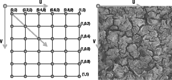
Figure 11-5. The texture coordinates for a grid of vertices (left) and the UV axes over a texture map (right)
In addition to the position and texture coordinate, you still need to calculate the normal, tangent, and binormal for each vertex. To do that, you will create the GenerateTerrainNormals and GenerateTerrainTangentBinormal methods, which you call at the end of the GenerateTerrainVertices method. First, here is the complete code for the GenerateTerrainVertices method:
private VertexPositionNormalTangentBinormalTexture[] GenerateTerrainVertices(

                                                int[] terrainIndices)

{

    float halfTerrainWidth = (vertexCountX - 1) * blockScale * 0.5f;

    float halfTerrainDepth = (vertexCountZ - 1) * blockScale * 0.5f;


    // Texture coordinates

    float tu = 0;

    float tv = 0;

    float tuDerivative = 1.0f / (vertexCountX - 1);

    float tvDerivative = 1.0f / (vertexCountZ - 1);


    int vertexCount = 0;

    VertexPositionNormalTangentBinormalTexture[] vertices =

    new VertexPositionNormalTangentBinormalTexture[vertexCountX * vertexCountZ];


    // Set vertices position and texture coordinate

    for (float i = -halfTerrainDepth; i <= halfTerrainDepth; i += blockScale)

    {

        tu = 0.0f;

        for (float j = -halfTerrainWidth; j <= halfTerrainWidth; j += blockScale)

        {

            vertices[vertexCount].Position =

            new Vector3(j, heightMap[vertexCount].R * heightScale, i);

            vertices[vertexCount].TextureCoordinate = new Vector2(tu, tv);


            tu += tuDerivative;

            vertexCount++;

        }


        tv += tvDerivative;

    }


    // Generate vertice's normal, tangent and binormal

    GenerateTerrainNormals(vertices, terrainIndices);

    GenerateTerrainTangentBinormal(vertices, terrainIndices);


    return vertices;

}
Generating the Normal Vectors of the Vertices
In your HLSL effect that will render the terrain, you'll want to make sure your terrain is correctly lit. In order to perform lighting calculations, you'll need to know the normal vector in each vertex.
The normal vector of each vertex in a triangle is equal to the normal vector of the triangle, which is the vector perpendicular to the triangle. So, to calculate the normal of the vertices in a triangle, you need to calculate the normal of the triangle. You could calculate the triangle normal by taking a cross product between two vectors formed by its vertices, such as (v1-v0) and (v2-v0), because the cross product returns a vector perpendicular to these two vectors.
In a vertex grid, most vertices are shared among up to six triangles. Because of this, the normal in each shared vertex is the mean of the normals of the triangles that use the vertex. Thus, you need to sum the normal vectors of each triangle adjacent to the triangle you're working with. Then you must normalize this normal of each vertex, making the normals a unitary length but keeping the direction. Normal vectors are used in lighting calculations, and they must be of unitary length to yield correct lighting. You use the following code for the GenerateTerrainNormals method to generate the normals of the terrain's vertices:
private void GenerateTerrainNormals(VertexPositionNormalTangentBinormal[] vertices,

    int[] indices)

{

    for (int i = 0; i < indices.Length; i += 3)

    {

        // Get the vertex position (v1, v2, and v3)

        Vector3 v1 = vertices[indices[i]].Position;

        Vector3 v2 = vertices[indices[i + 1]].Position;

        Vector3 v3 = vertices[indices[i + 2]].Position;

        // Calculate vectors v1->v3 and v1->v2 and the normal as a cross product

        Vector3 vu = v3 - v1;

        Vector3 vt = v2 - v1;

        Vector3 normal = Vector3.Cross(vu, vt);

        normal.Normalize();


        // Sum this normal with the current vertex normal of the three vertices

        vertices[indices[i]].Normal += normal;

        vertices[indices[i + 1]].Normal += normal;

        vertices[indices[i + 2]].Normal += normal;

    }


    // After calculating all the normals, normalize them

    for (int i = 0; i < vertices.Length; i++)

        vertices[i].Normal.Normalize();

}
Generating the Tangent and Binormal Vectors of the Vertices
The custom effect you'll create for the terrain uses a technique named normal mapping, which increases the visual details of the terrain, without adding extra triangles. Before you can start coding the normal mapping technique, every mesh's vertex must have tangent, binormal, and normal vectors. While the normal vector of a vertex is perpendicular to the terrain in that vertex, the tangent and binormal vectors touch (but not intersect!) the terrain in that vertex. The tangent, binormal, and normal vectors are also perpendicular to each other, and they form what is called the tangent base. Figure 11-6 illustrates the tangent, binormal, and normal vectors for different points of two different surfaces.
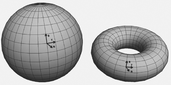
Figure 11-6. Tangent, binormal, and normal vectors
You can calculate the tangent vector of each vertex in the vertex grid: it's the vector that starts at one vertex and ends in the next vertex of the grid. This way, the tangent vector is oriented with the grid's x axis. Note that the tangent vector of the last vertex in a line on the grid is calculated as a vector that starts in the penultimate vertex of the line and ends in the last vertex.
Since all three vectors need to be perpendicular to each other, you can obtain the binormal vector using a cross product between the vertices' tangent and normal. Figure 11-7 shows the tangent, binormal, and normal vectors of a flat grid of vertices.
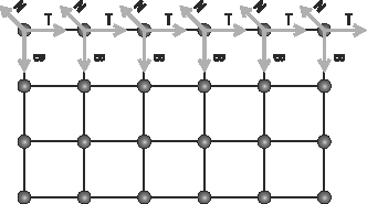
Figure 11-7. Tangent, binormal, and normal vectors of some vertices in a flat grid
Use the following code for the GenerateTerrainTangentBinormal method to calculate the vertices' tangent and binormal vectors:
public void GenerateTerrainTangentBinormal(

    VertexPositionNormalTangentBinormal[] vertices, int[] indices)

{

    for (int i = 0; i < vertexCountZ; i++)

    {

        for (int j = 0; j < vertexCountX; j++)

        {

            int vertexIndex = j + i * vertexCountX;

            Vector3 v1 = vertices[vertexIndex].Position;


            // Calculate the tangent vector

            if (j < vertexCountX - 1)

            {

                Vector3 v2 = vertices[vertexIndex + 1].Position;

                vertices[vertexIndex].Tangent = (v2 - v1);

            }

            // Special case: last vertex of the plane in the X axis

            else

            {

                Vector3 v2 = vertices[vertexIndex - 1].Position;

                vertices[vertexIndex].Tangent = (v1 - v2);

            }


            // Calculate binormal as a cross product (Tangent x Normal)

            vertices[vertexIndex].Tangent.Normalize();

            vertices[vertexIndex].Binormal = Vector3.Cross(

                vertices[vertexIndex].Tangent, vertices[vertexIndex].Normal);

        }

    }

}
An Overview of Terrain Techniques
At this point, you have all the code you need to read in a height map from an image file on disk, create the corresponding vertices and indices, and load them into a vertex buffer and an index buffer. To render these triangles to the screen, you could use XNA's BasicEffect class, and since you've provided valid normals, the BasicEffect class would add the correct lighting to your terrain. However, there is no way to instruct the BasicEffect class to use multiple textures on your terrain or perform other custom enhancements.
In the remainder of this chapter, we'll show you how to code your own HLSL effect that adds multitexturing and normal mapping to your terrain. For the terrain rendering, you'll create a custom effect that uses multitexturing and normal mapping. Before you get to coding, let's take a look at how these two techniques work.
The Multitexturing Technique
Using multitexturing, you can apply different layers of textures over the terrain, such as sand, grass, rocks, snow, and so on. Then you can generate the terrain's texture by blending the textures together, allowing for smooth transitions from one texture to another. For example, some parts of the terrain could have grass, others rocks, and some parts sand and grass, or snow and rocks, and so on. Figure 11-8 shows how some textures are combined to form a new texture.
In the terrain effect you're going to create, you'll combine the terrain textures based on a separate texture, called the alpha map (or transparency map), which defines the intensity of each texture over the terrain. It is called alpha map because, for each pixel, it contains four values, indicating how much of each of the four base textures needs to be blended to obtain the final color in that pixel. The alpha map is a regular RGBA color texture, with 8 bits per channel, and you're using each of the four color channels to store the intensity of the four different texture layers. This means that this technique uses five textures: four regular textures and one alpha map. For each pixel, the red value of the alpha map tells you how much you need of the first texture, the green value indicates how much you need of the second texture, and so on.
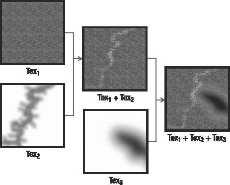
Figure 11-8. Multitexturing—combining three different textures to create a new one
The Normal Mapping Technique
Using the normal mapping technique, you can add the illusion of small-scale details to the terrain's mesh, without needing to increase the complexity of its mesh. You create this illusion by slightly manipulating the lighting in each pixel of your terrain. Variations in lighting are created by the deviated normals. Remember that the amount of lighting falling onto a triangle is determined by the normals of its vertices. Differing the illumination based on deviated normals creates the illusion of a 3D contour, as shown on the right side of Figure 11-9.
For example, consider the case of a stone wall. The default normals would all be pointing outward, perpendicular to the wall. With normal mapping, you adjust the normals in the pixels near the edges of the stones. The closer the pixel to the edge of the stone, the more deviated the normal should be. This example is shown in Figure 11-9.
Obviously, you need to know how much to deviate each normal beforehand. Therefore, the required normal deviations are stored in a normal map, which accompanies a texture. This is why you needed to calculate the tangent, binormal, and normal vectors for each vertex. In such a normal map, each pixel stores the x, y, and z components of the new surface normal inside its R, G, and B color channels.
Notice that the normal x, y, and z axes aren't on the world coordinates. Instead, they're placed in the tangent base coordinates. This way, the normal map is independent of the surface and can be applied to any type of object.
One of the weaknesses of the normal mapping technique is that when the surface is visualized from grazing angles (the angle between the surface normal and a viewer close to 90 degrees), the illusion of normal mapping disappears, and the surface will seem flat.
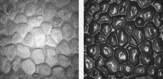
Figure 11-9. Texturing only (left) and texturing plus normal mapping (right)
The terrain effect you'll create for terrain rendering in the next section will support two omnidirectional light sources and multitexturing with four diffuse textures, as this is not so difficult to implement and already provides a nice final result. Later in the chapter, you will expand the effect by adding normal mapping.
Creating the Terrain Effect
To begin creating the terrain effect that uses multitexturing, open a new file and name it Terrain.fx. As good practice, you should start by defining the uniform variables. Remember from the discussion in Chapter 9 that these uniform variables should be set by XNA before the rendering operation starts and remain constant during the rendering of one frame. Also remember that they are globally accessible by your shaders.
Add the following to the top of your Terrain.fx file:
// -------------------------------------------------

// Matrices

// -------------------------------------------------

float4×4 matW   : World;

float4×4 matVI  : ViewInverse;

float4×4 matWVP : WorldViewProjection;


// Materials

// -------------------------------------------------

float3 diffuseColor;

float3 specularColor;

float specularPower;

// Lights

// -------------------------------------------------

float3 ambientLightColor;

float3 light1Position;

float3 light1Color;

float3 light2Position;

float3 light2Color;


// UV tiles: 0-4 diffuse textures

float2 uv1Tile;

float2 uv2Tile;

float2 uv3Tile;

float2 uv4Tile;

float2 uvNormalTile;
These are the uniform variables needed for the entire effect, including both multitexturing and normal mapping. The world matrix is needed to take into account all transformations set on the terrain, such as a relocation, scaling, and rotation of the entire terrain. The ViewInverse matrix is required, as it contains the position of the camera in the 3D world. The WorldViewProjection matrix is needed to transform all 3D coordinates to 2D screen coordinates.
For the terrain material, you need to know the color and shininess of each of your two lights. You also need to know the position and color for each light, as well as how much ambient light there is present in the scene. Finally, the tiling variables allow you to stretch and shrink the textures over the terrain from within XNA.
After the uniform variables, you should define the textures that your effect needs. In total, the terrain effect will use six textures: four regular textures for the diffuse color, an alpha map, and a normal map. As explained in the previous section, the alpha map defines how the diffuse textures will be combined to form the final terrain color. Add the textures to your Terrain.fx file, as follows:
// Textures

// -------------------------------------------------

texture diffuseTexture1;

texture diffuseTexture2;

texture diffuseTexture3;

texture diffuseTexture4;

texture alphaTexture;

texture normalTexture;
This concludes the list of all variables that can be set from within your XNA application. For each texture, you also need a texture sampler, so add these samplers to your Terrain.fx file:
sampler2D diffuseSampler1 = sampler_state {

    Texture = <diffuseTexture1>;

    MagFilter = Linear;

    MinFilter = Linear;

    MipFilter = Linear;

    AddressU = Wrap;

    AddressV = Wrap;

};

sampler2D diffuseSampler2 = sampler_state {

    Texture = <diffuseTexture2>;

    MagFilter = Linear;

    MinFilter = Linear;

    MipFilter = Linear;

    AddressU = Wrap;

    AddressV = Wrap;

};


sampler2D diffuseSampler3 = sampler_state {

    Texture = <diffuseTexture3>;

    MagFilter = Linear;

    MinFilter = Linear;

    MipFilter = Linear;

    AddressU = Wrap;

    AddressV = Wrap;

};


sampler2D diffuseSampler4 = sampler_state {

    Texture = <diffuseTexture4>;

    MagFilter = Linear;

    MinFilter = Linear;

    MipFilter = Linear;

    AddressU = Wrap;

    AddressV = Wrap;

};


sampler2D alphaSampler = sampler_state {

      Texture = <alphaTexture>;

      MinFilter = Linear;

      MagFilter = Linear;

      MipFilter = Linear;

      AddressU = Wrap;

      AddressV = Wrap;

};


sampler2D normalSampler = sampler_state {

      Texture = <normalTexture>;

      MinFilter = linear;

      MagFilter = linear;

      MipFilter = linear;

      AddressU = Wrap;

      AddressV = Wrap;

};
Creating the Vertex Input and Output Structures for the Terrain Effect
Before you start work on your vertex shader, you should define which information is contained inside each vertex sent by XNA, so the vertex shader knows which information to expect. All vertices that XNA sends to your vertex shader contain the vertex position, texture coordinate, and tangent base (tangent, binormal, and normal vectors), so put this struct at the top of your Terrain.fx file.
struct a2v

{

    float4 position   : POSITION;

    float2 uv0        : TEXCOORD0;

    float3 tangent    : TANGENT;

    float3 binormal   : BINORMAL;

    float3 normal     : NORMAL;

};
Next, define which information the vertex shader should generate for each vertex. This is defined by what your pixel shader will need. The final pixel shader will need the coordinates of the six textures used, which would require six float2 objects. However, since the GPU does all the processing in tuples of four, you can gain better performance by storing two float2 objects together in a float4 object, resulting in three float4 objects.
Your pixel shader will need the view vector, the two lighting vectors (all the vectors are in the tangent space), and the normal to perform correct lighting calculations. The rasterizer stage between your vertex shader and pixel shader needs the 2D position of the vertex (as explained in Chapter 9):
struct v2f

{

    float4 hposition        : POSITION;

    float4 uv1_2            : TEXCOORD0;

    float4 uv3_4            : TEXCOORD1;

    float4 uv5_6            : TEXCOORD2;

    float3 eyeVec           : TEXCOORD4;

    float3 lightVec1        : TEXCOORD5;

    float3 lightVec2        : TEXCOORD6;

    float3 normal           : TEXCOORD7;

};
Creating the Vertex Shader for the Terrain Effect
The most basic and only required task of a vertex shader is to calculate the final 2D screen coordinate of every vertex. Whenever you're rendering a 3D scene, this calculation is done by transforming the 3D coordinate of the vertex by combining the world, view, and projection matrices:
OUT.hposition = mul(IN.position, matWVP); // Vertex position in screen space
Now you should calculate the view vector and the two lighting vectors and transform their coordinate to the tangent space (using the tangentSpace matrix). A vector from point A to point B is found by subtracting A from B. The view vector is the vector between the current vertex and the camera (found in the inverse view matrix). A light vector is the vector between the current vertex and the light position:
float3 worldPosition = mul(IN.position, matW).xyz;

OUT.eyeVec = matVI[3].xyz - worldPosition;

OUT.lightVec1 = light1Position - worldPosition;

OUT.lightVec2 = light2Position - worldPosition;
Finally, calculate all the texture coordinates using the default texture coordinate of the surface and some tile factors. Each float4 object stores two texture coordinates, except for the last, which stores a texture coordinate and two zeros.
OUT.uv1_2 = float4(IN.uv0 * uv1Tile, IN.uv0 * uv2Tile);

OUT.uv3_4 = float4(IN.uv0 * uv3Tile, IN.uv0 * uv4Tile);

OUT.uv5_6 = float4(IN.uv0, 0, 0);
The complete vertex processing code follows:
v2f TerrainVS(a2v IN)

{

    v2f OUT;


    OUT.hposition = mul(IN.position, matWVP);

    OUT.normal = IN.normal;


    // Light vectors

    float3 worldPosition = mul(IN.position, matW).xyz;

    OUT.eyeVec = matVI[3].xyz - worldPosition;

    OUT.lightVec1 = light1Position - worldPosition;

    OUT.lightVec2 = light2Position - worldPosition;


    // Multitexturing

    OUT.uv1_2 = float4(IN.uv0 * uv1Tile, IN.uv0 * uv2Tile);

    OUT.uv3_4 = float4(IN.uv0 * uv3Tile, IN.uv0 * uv4Tile);

    OUT.uv5_6 = float4(IN.uv0, 0, 0);


    return OUT;

}
Pixel Processing for the Terrain Effect
All values generated by the vertex shader are interpolated by the rasterizer, a process that can change the length of the vectors passed from the vertex shader to the pixel shader. Therefore, the first thing you need to do in the pixel shader is normalize all the vectors, making sure their length becomes exactly 1.0 again. Remember that this needs to be done to yield correct lighting.
float3 eyeVec = normalize(IN.eyeVec);

float3 lightVec1 = normalize(IN.lightVec1);

float3 lightVec2 = normalize(IN.lightVec2);

float3 halfwayVec1 = normalize(lightVec1 + eyeVec);

float3 halfwayVec2 = normalize(lightVec2 + eyeVec);

float3 normal = normalize(IN.normal);
At this point, you have all the vectors necessary for the lighting calculation. You'll do the lighting calculation using the Phong equation, which is implemented in the phongShading method. This method takes into account the light color, the halfway vector, and the angle between the normal and the light direction. As a result, it returns how much the object should be lit in the diffuseColor output and how much more shiny the object should be in the specularColor output. Put this method immediately after your vertex shader:
void phongShading(in float3 normal, in float3 lightVec, in float3 halfwayVec,

                  in float3 lightColor, out float3 diffuseColor,

                  out float3 specularColor)

{

    float diffuseInt = saturate(dot(normal, lightVec));

    diffuseColor = diffuseInt * lightColor;

    float specularInt = saturate(dot(normal, halfwayVec));

    specularInt = pow(specularInt, specularPower);

    specularColor = specularInt * lightColor;

}
Use the method in your pixel shader to calculate the diffuse and specular lighting contributions of both lights in your scene:
// Calculate diffuse and specular color for each light

float3 diffuseColor1, diffuseColor2;

float3 specularColor1, specularColor2;

phongShading(normal, lightVec1, halfwayVec1, light1Color,

             diffuseColor1, specularColor1);

             phongShading(normal, lightVec2, halfwayVec2, light2Color

, diffuseColor2, specularColor2);
Now you know how much the pixel should be lit, but you still need to know the color of the pixel. You calculate this color by sampling and combining the four diffuse textures that are applied to the terrain according to the values in the alpha map texture. Each component of the alpha map stores a value used to linearly interpolate between the colors of the diffuse textures:
float3 color1 = tex2D(diffuseSampler1, IN.uv1_2.xy);

float3 color2 = tex2D(diffuseSampler2, IN.uv1_2.zw);

float3 color3 = tex2D(diffuseSampler3, IN.uv3_4.xy);

float3 color4 = tex2D(diffuseSampler4, IN.uv3_4.zw);

float4 alpha = tex2D(alphaSampler, IN.uv5_6.zw);


// Combine using the alpha map

float3 combinedColor = lerp(color1, color2, alpha.x);

combinedColor = lerp(combinedColor, color3, alpha.y);

combinedColor = lerp(combinedColor, color4, alpha.z);
Finally, you combine the lighting conditions with the base color of the pixel by multiplying them:
float4 finalColor;

finalColor.a = 1.0f;

finalColor.rgb = combinedColor * ((diffuseColor1 + diffuseColor2) *

    materialDiffuseColor + ambientLightColor) + (specularColor1 +

    specularColor2) * materialSpecularColor;
The complete pixel shader code follows:
float4 TerrainPS(v2f IN) : COLOR0

{

    float3 eyeVec = normalize(IN.eyeVec);

    float3 lightVec1 = normalize(IN.lightVec1);

    float3 lightVec2 = normalize(IN.lightVec2);

    float3 halfwayVec1 = normalize(lightVec1 + eyeVec);

    float3 halfwayVec2 = normalize(lightVec2 + eyeVec);

    float3 normal = normalize(IN.normal);


    float3 color1 = tex2D(diffuseSampler1, IN.uv1_2.xy);

    float3 color2 = tex2D(diffuseSampler2, IN.uv1_2.zw);

    float3 color3 = tex2D(diffuseSampler3, IN.uv3_4.xy);

    float3 color4 = tex2D(diffuseSampler4, IN.uv3_4.zw);

    float4 alpha = tex2D(alphaSampler, IN.uv5_6.xy);


    float3 combinedColor = lerp(color1, color2, alpha.x);

    combinedColor = lerp(combinedColor, color3, alpha.y);

    combinedColor = lerp(combinedColor, color4, alpha.z);


    // Calculate diffuse and specular color for each light

    float3 diffuseColor1, diffuseColor2;

    float3 specularColor1, specularColor2;

    phongShading(normal, lightVec1, halfwayVec1, light1Color,

                 diffuseColor1, specularColor1);

    phongShading(normal, lightVec2, halfwayVec2, light2Color,

                 diffuseColor2, specularColor2);


    // Phong lighting result

    float4 finalColor;

    finalColor.a = 1.0f;

    finalColor.rgb = combinedColor * ((diffuseColor1 + diffuseColor2)

                 * diffuseColor + ambientLightColor)

                 + (specularColor1 + specularColor2) * specularColor;


    return finalColor;

}
Defining the Technique for the Terrain Effect
To finish your effect, you need to define a technique that combines the vertex shader and pixel shader you just defined. Use this code to finalize your Terrain.fx file:
technique TerrainMultiTextured

{

    pass p0

    {

        VertexShader = compile vs_2_0 TerrainVS();

        PixelShader = compile ps_2_0 TerrainPS();

    }

}
In the technique definition, you indicate the technique is rendered in a single pass, which vertex and pixel shader to use, and that both your vertex and pixel shaders can be compiled for shader version 2.0.
Setting the Effect Material
So far, so good, for your HLSL code. To manage the terrain effect in your XNA application, you'll create the TerrainEffect class, which will query and store all of the parameters for the effect. The helper classes help you modify and manage the effect parameters, as explained in Chapter 9. TerrainEffect will be fairly complex, so you'll also create the TerrainMaterial class, to help you configure the terrain effect. (For brevity, we won't show the code for the TerrainEffect class here, but it is available with the rest of the downloadable code for this book.)
The TerrainMaterial class stores the surface material as an attribute of type LightMaterial and the surface textures as attributes of type TextureMaterial. Following is the code for the TerrainMaterial class:
public class TerrainMaterial

{

    // Surface material

    LightMaterial lightMaterial;


    // Diffuse textures

    TextureMaterial diffuseTexture1;

    TextureMaterial diffuseTexture2;

    TextureMaterial diffuseTexture3;

    TextureMaterial diffuseTexture4;


    // Alpha map

    TextureMaterial alphaMapTexture;


    // Normal map

    TextureMaterial normalMapTexture;

    // Properties

    public LightMaterial LightMaterial

    {

        get { return lightMaterial; }

        set { lightMaterial = value; }

    }


    public TextureMaterial DiffuseTexture1

    {

        get { return diffuseTexture1; }

        set { diffuseTexture1 = value; }

    }


    public TextureMaterial DiffuseTexture2

    {

        get { return diffuseTexture2; }

        set { diffuseTexture2 = value; }

    }


    public TextureMaterial DiffuseTexture3

    {

        get { return diffuseTexture3; }

        set { diffuseTexture3 = value; }

    }


    public TextureMaterial DiffuseTexture4

    {

        get { return diffuseTexture4; }

        set { diffuseTexture4 = value; }

    }


    public TextureMaterial AlphaMapTexture

    {

        get { return alphaMapTexture; }

        set { alphaMapTexture = value; }

    }


    public TextureMaterial NormalMapTexture

    {

        get { return normalMapTexture; }

        set { normalMapTexture = value; }

    }


    public TerrainMaterial()

    {

    }

}
To configure the terrain effect, inside the Terrain class, you'll create the SetEffectMaterial method. You'll use this method to configure all the effect parameters, through the TerrainEffect helper class, before the terrain rendering.
In your scene, you'll manage the cameras and lights using the CameraManager and LightManager classes you created in Chapter 10. You can add these classes to the service container of the Game class.
Tip Your main Game object has a Services property, which stores your active game services. A good habit is to make a service out of each main component of your game, such as the camera, light manager, and terrain. This way, during runtime, all components of your game can query the services container for the active camera, the active light manager, and so on. The benefit is that you can do things like suddenly change the active camera from a first-person camera to a third-person camera, without needing to inform the other components in your game. They will simply ask the main Game object for the currently active camera; they don't need to know about any behind-the-scenes changes.
Using the service container, you can get the light manager (LightManager) and obtain the scene lights, which are used by the effect:
// Get the light manager

LightManager lightManager = Game.Services.GetService(

    typeof(LightManager)) as LightManager;


// Get the first two lights from the light manager

PointLight light0 = lightManager[0] as PointLight;

PointLight light1 = lightManager[1] as PointLight;


// Lights

effect.AmbientLightColor = lightManager.AmbientLightColor;

effect.Light1Position = light0.Position;

effect.Light1Color = light0.Color;

effect.Light2Position = light1.Position;

effect.Light2Color = light1.Color;
Also, by using the service container, you can get the camera manager (CameraManager) and obtain the active camera from it, and you can read the terrain transformation from its transformation attribute of type Transformation:
// Get the camera manager

cameraManager = Game.Services.GetService(

    typeof(CameraManager)) as CameraManager;


// Set the camera view and projection

effect.View = cameraManager.ActiveCamera.View;

effect.Projection = cameraManager.ActiveCamera.Projection;

// Set the terrain transformation

effect.World = transformation.Matrix;
Finally, you configure the terrain material and the textures through the LightMaterial and TextureMaterial attributes of the TerrainMaterial classes. Following is the code for the SetEffectMaterial method:
private void SetEffectMaterial()

{

    // Get the light manager

    LightManager lightManager = Game.Services.GetService(

        typeof(LightManager)) as LightManager;


    // Get the first two lights from the light manager

    PointLight light0 = lightManager[0] as PointLight;

    PointLight light1 = lightManager[1] as PointLight;

    // Lights

    effect.AmbientLightColor = lightManager.AmbientLightColor;

    effect.Light1Position = light0.Position;

    effect.Light1Color = light0.Color;

    effect.Light2Position = light1.Position;

    effect.Light2Color = light1.Color;


    // Get the camera manager

    cameraManager = Game.Services.GetService(

        typeof(CameraManager)) as CameraManager;


    // Set the camera view and projection

    effect.View = cameraManager.ActiveCamera.View;

    effect.Projection = cameraManager.ActiveCamera.Projection;


    // Set the terrain transformation

    effect.World = transformation.Matrix;


    // Material

    effect.DiffuseColor = terrainMaterial.LightMaterial.DiffuseColor;

    effect.SpecularColor = terrainMaterial.LightMaterial.SpecularColor;

    effect.SpecularPower = terrainMaterial.LightMaterial.SpecularPower;

    // Textures

    effect.DiffuseTexture1 = terrainMaterial.DiffuseTexture1.Texture;

    effect.DiffuseTexture2 = terrainMaterial.DiffuseTexture2.Texture;

    effect.DiffuseTexture3 = terrainMaterial.DiffuseTexture3.Texture;

    effect.DiffuseTexture4 = terrainMaterial.DiffuseTexture4.Texture;

    effect.NormalMapTexture = terrainMaterial.NormalMapTexture.Texture;

    effect.AlphaMapTexture = terrainMaterial.AlphaMapTexture.Texture;

    // Texture UVs

    effect.TextureUV1Tile = terrainMaterial.DiffuseTexture1.UVTile;

    effect.TextureUV2Tile = terrainMaterial.DiffuseTexture2.UVTile;

    effect.TextureUV3Tile = terrainMaterial.DiffuseTexture3.UVTile;

    effect.TextureUV4Tile = terrainMaterial.DiffuseTexture4.UVTile;

    effect.TextureUVNormalTile = material.NormalMapTexture.UVTile;

}
Drawing the Terrain
At this point, you have stored the vertices that define the position, normal, texture coordinate, and so on. You have defined the indices that connect your vertices to form triangles, which make up the grid of your terrain. And you've created a custom effect that will be used to render the triangles to the screen, sampling their colors from four textures at the same time. Now you're ready to instruct XNA to actually render the terrain.
To draw the terrain, you initially need to call the SetEffectMaterial method, which configures the terrain effect. Then you set the terrain's vertex buffer, the index buffers, and the vertex declaration on the graphics device. You use the vertex declaration to inform the graphics device about the vertex format you're using, so that it can correctly process the vertices:
// Set mesh vertex and index buffer

GraphicsDevice.Vertices[0].SetSource(vb, 0,

    VertexPositionNormalTangentBinormal.SizeInBytes);

GraphicsDevice.Indices = ib;


// Set the vertex declaration

GraphicsDevice.VertexDeclaration = this.vertexDeclaration;
The next step is to begin the effects and go over all the effects' passes, drawing the terrain for each pass. Although your effect has only one pass, it is good practice to loop through all available passes as shown in the following code, so you can easily enhance your effect later. To draw the terrain's mesh, you use the DrawIndexedPrimitives method of XNA's GraphicsDevice. You use this method because you're drawing primitives defined by indices. Following is the complete code for the Draw method from the Terrain class:
public override void Draw(GameTime time)

{

    // Configure TerrainEffect

    SetEffectMaterial();

    // Set mesh vertex and index buffer

    GraphicsDevice.Vertices[0].SetSource(vb, 0,

        VertexPositionNormalTangentBinormal.SizeInBytes);

    GraphicsDevice.Indices = ib;


    // Set the vertex declaration

    GraphicsDevice.VertexDeclaration = this.vertexDeclaration;


    effect.Begin();

    // Loop through all effect passes

    foreach (EffectPass pass in effect.CurrentTechniquePasses)

    {

        pass.Begin();

        // Draw the mesh

        GraphicsDevice.DrawIndexedPrimitives(PrimitiveType.TriangleList,

            0, 0, numVertices, 0, numTriangles);

        pass.End();

    }

    effect.End();

}
Running this application should render your terrain, complete with multitexturing and correct lighting.
Extending the Terrain Effect with Normal Mapping
After adding your terrain effect, you should see a beautifully colored terrain on your screen. To improve this result, you'll extend your effect with normal mapping. At the end of this section, you'll have a normal-mapped, multitextured terrain. As with most effects, this will not change the shape of the terrain, as you will enhance only the visual quality of the image.
Note Here, we briefly cover the changes required to enable your effect with normal mapping. The book Real-Time Rendering, Second Edition, by Tomas Akenine-Möller and Eric Haines (AK Peters, Ltd., 2002) is a good reference for more information about the Phong algorithm and the normal mapping technique.
In the normal mapping technique, you adjust the normal in each pixel, as defined in a predefined normal map. The deviated normals stored in the normal map are specified in tangent space, which means you first need to find the x, y, and z axes of this tangent space. As explained earlier, these are defined by the normal, tangent, and binormal. Because these are different for each vertex, each vertex has a different tangent space, so this space should be calculated for each vertex in the vertex shader.
Vertex Processing for Normal Mapping
Add this code to your vertex shader to calculate the matrix that allows you to transform positions and vectors from world space to tangent space:
float3×3 tangentSpace = float3×3(IN.tangent, IN.binormal, IN.normal);

tangentSpace = mul(tangentSpace, matW);

tangentSpace = transpose(tangentSpace);
Remember that when you perform operations on two vectors, both vectors need to be defined in the same space. Because your normal is defined in tangent space, you'll want to transform all vectors needed for the lighting calculations into tangent space. Replace the corresponding part of your vertex shader with this code:
// Light vectors

float3 worldPosition = mul(IN.position, matW).xyz;

OUT.eyeVec = mul(matVI[3].xyz - worldPosition, tangentSpace);

OUT.lightVec1 = mul(light1Position - worldPosition, tangentSpace);

OUT.lightVec2 = mul(light2Position - worldPosition, tangentSpace);
Finally, you need to pass the texture coordinate for sampling in the normal map. This should be placed in the uv5_6 output, which still has two empty spaces:
OUT.uv5_6 = float4(IN.uv0, IN.uv0 * uvNormalTile);
Pixel Processing for Normal Mapping
In your pixel shader, you need to find the adjusted normal vector. This is done by sampling the RGB color values from the normal map. Color values are constrained to the [0,1] interval; therefore, you need to scale them into the [−1,1] interval for the x, y, and z coordinates:
float3 normal = tex2D(normalSampler, IN.uv5_6.zw);

normal.xy = normal.xy * 2.0 - 1.0;
Finally, the z component of the adjusted normal needs to be found so that the total length of the new normal is exactly 1.0:
normal.z = sqrt(1.0 - dot(normal.xy, normal.xy));
Figure 11-10 shows the final result of the terrain rendering. Notice that the terrain surface is flat. However, the normal map adds the detail of a stone pattern over the entire surface.
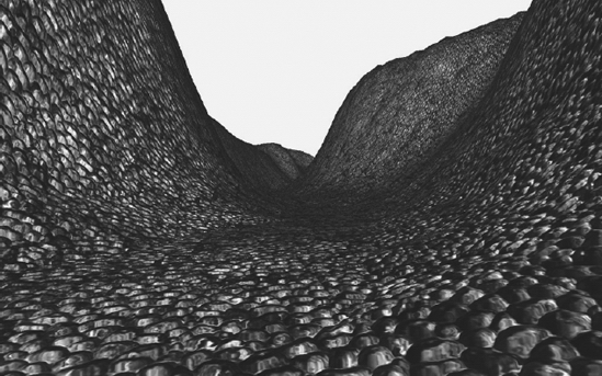
Figure 11-10. Final result of the terrain rendering
Querying the Terrain's Height
To guarantee that all scene objects remain exactly on the terrain, you should be able to query the terrain's height at any position. For example, you would query the terrain's height if you wanted to make sure the feet of a character appeared on the ground properly. You can calculate the height of any position over the terrain starting from the terrain's vertices, whose heights you stored in the height map.
To query the height of the terrain at an arbitrary world position, you first need to calculate this position relative to the terrain's vertex grid. You can do this by subtracting the queried world position from the terrain's origin position, making sure to take the terrain's world translation and rotation into account. Then you need to know in which quad of the terrain grid the position you are querying is located, which you can do by dividing the calculated position (relative to the terrain) by the terrain's block scale. Figure 11-11 shows an object in the world position (52, 48), where its position in the terrain grid is (1, 1).
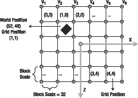
Figure 11-11. Object position relative to the terrain grid
The code to calculate the x,z position of an object over the terrain grid follows:
// Get the position relative to the terrain grid

Vector2 positionInGrid = new Vector2(

    positionX - (StartPosition.X + Transformation.Translate.X),

    positionZ - (StartPosition.Y + Transformation.Translate.Z));


// Calculate the grid position

Vector2 blockPosition = new Vector2(

    (int)(positionInGrid.X / blockScale),

    (int)(positionInGrid.Y / blockScale));
After you calculate in which quad of the grid the position is located, you need to find out in which of the two triangles of this quad it is located. You can do this by calculating the position of the object inside the quad and verifying if its position in the x axis is higher than its position in the z axis. When the object's x position is higher than the z position, the object will be found on the top triangle; otherwise, if the value is smaller, the object will be found on the bottom triangle, as shown in Figure 11-12.
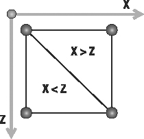
Figure 11-12. A block in the terrain grid. If the x position inside the block is bigger than the z position, the object is in the top triangle. Otherwise, the object is in the bottom triangle.
After finding in which triangle the object is positioned, you can obtain the height of a position inside this triangle through a bilinear interpolation of the height of the triangle's vertices. Use the following code for the GetHeight method to calculate the height of a terrain's position:
private float GetHeight(float positionX, float positionZ)

{

    float height = −999999.0f;

    if (heightmap == null) return height;


    // Get the position relative to the terrain grid

    Vector2 positionInGrid = new Vector2(

        positionX - (StartPosition.X + Transformation.Translate.X),

        positionZ - (StartPosition.Y + Transformation.Translate.Z));


    // Calculate the grid position

    Vector2 blockPosition = new Vector2(

        (int)(positionInGrid.X / blockScale),

        (int)(positionInGrid.Y / blockScale));


    // Check if the object is inside the grid

    if (blockPosition.X >= 0 && blockPosition.X < (vertexCountX - 1) &&

        blockPosition.Y >= 0 && blockPosition.Y < (vertexCountZ - 1))

    {

        Vector2 blockOffset = new Vector2(

            blockPosition.X - (int)blockPosition.X,

            blockPosition.Y - (int)blockPosition.Y);

        // Get the height of the four vertices of the grid block

        int vertexIndex = (int)blockPosition.X +

            (int)blockPosition.Y * vertexCountX;

        float height1 = heightmap[vertexIndex + 1];

        float height2 = heightmap[vertexIndex];

        float height3 = heightmap[vertexIndex + vertexCountX + 1];

        float height4 = heightmap[vertexIndex + vertexCountX];


        // Top triangle

        float heightIncX, heightIncY;

        if (blockOffset.X > blockOffset.Y)

        {

            heightIncX = height1 - height2;

            heightIncY = height3 - height1;

        }

        // Bottom triangle

        else

        {

            heightIncX = height3 - height4;

            heightIncY = height4 - height2;

        }


        // Linear interpolation to find the height inside the triangle

        float lerpHeight = height2 + heightIncX * blockOffset.X +

            heightIncY * blockOffset.Y;

        height = lerpHeight * heightScale;

    }

    return height;

}
Notice that you use this method only to ensure that all scene objects are positioned over the terrain. To produce a realistic interaction between the objects and the terrain (such as bouncing), you would need to implement a physics system.
Ray and Terrain Collision
To detect when an object in the scene intersects a part of the terrain, you need to create some collision test methods. One useful collision test is between a ray and the terrain. For example, if an object is moving in the scene, you can trace a ray in the direction in which this object is moving and get the distance between it and the terrain.
To check the ray and terrain collision, you'll do a collision test between the ray and the terrain's height map, instead of testing the ray against the terrain's mesh (many triangles). The collision test will be divided in two parts. In the first part, you'll do a linear search on the ray until you find a point outside (above) and another inside (below) the terrain. Then you'll perform a binary search between these two points to find the exact collision point with the terrain. Figure 11-13 illustrates the linear search processes, where the nearest points outside and inside the terrain are found.
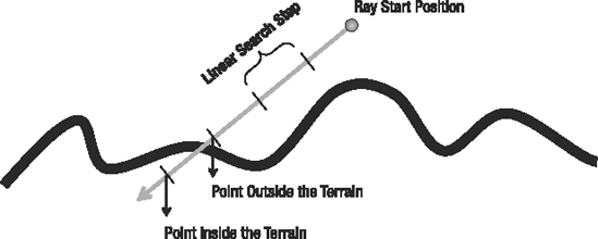
Figure 11-13. Linear search used to find one point inside and another outside the terrain
You can use the following code to perform the linear search on the terrain:
// A good ray step is half of the blockScale

Vector3 rayStep = ray.Direction * blockScale * 0.5f;

Vector3 rayStartPosition = ray.Position;


// Linear search - Loop until you find a point inside and outside the terrain

Vector3 lastRayPosition = ray.Position;

ray.Position += rayStep;

float height = GetHeight(ray.Position);

while (ray.Position.Y > height && height >= 0)

{

    lastRayPosition = ray.Position;

    ray.Position += rayStep;

    height = GetHeight(ray.Position);

}
After the linear search, the lastRayPosition variable stores the position outside the terrain, and the ray variable stores the position inside the terrain. You then need to perform a binary search between these two points to find the closest point to the terrain. You make this search with a fixed number of steps; 32 steps are usually enough for a good level of precision. The code for the binary search follows:
Vector3 startPosition = lastRayPosition;

Vector3 endPosition = ray.Position;


// Binary search with 32 steps. Try to find the exact collision point

for (int i = 0; i < 32; i++)

{

    // Binary search pass

    Vector3 middlePoint = (startPosition + endPosition) * 0.5f;

    if (middlePoint.Y < height) endPosition = middlePoint;

    else startPosition = middlePoint;

}


Vector3 collisionPoint = (startPosition + endPosition) * 0.5f;
You then create the Intersects method to check the intersection of a ray and the terrain. The Intersects method returns the distance between the ray's start point and the terrain's collision point, and if there is no collision with the terrain, the method will return null. Following is the code for the Intersects method of the Terrain class:
public float? Intersects(Ray ray)

{

    float? collisionDistance = null;

    Vector3 rayStep = ray.Direction * blockScale * 0.5f;

    Vector3 rayStartPosition = ray.Position;


    // Linear search - Loop until you find a point inside and outside the terrain

    Vector3 lastRayPosition = ray.Position;

    ray.Position += rayStep;

    float height = GetHeight(ray.Position);

    while (ray.Position.Y > height && height >= 0)

    {

        lastRayPosition = ray.Position;

        ray.Position += rayStep;

        height = GetHeight(ray.Position);

    }


    // If the ray collides with the terrain

    if (height >= 0)

    {

        Vector3 startPosition = lastRayPosition;

        Vector3 endPosition = ray.Position;


        // Binary search. Find the exact collision point

        for (int i = 0; i < 32; i++)

        {

            // Binary search pass

            Vector3 middlePoint = (startPosition + endPosition) * 0.5f;

            if (middlePoint.Y < height) endPosition = middlePoint;

            else startPosition = middlePoint;

        }

        Vector3 collisionPoint = (startPosition + endPosition) * 0.5f;

        collisionDistance = Vector3.Distance(rayStartPosition, collisionPoint);

    }

    return collisionDistance;

}
Summary
This chapter showed you how to create a terrain from a height map and render it to the screen. You first learned what height maps are and how to use them to represent the terrain. Then you learned how to create a vertex grid to represent the terrain's mesh, and how to use the height map values to change the height of the vertices of the grid. You also saw how to calculate the attributes needed for multitexturing, lighting, and normal mapping for each vertex in the vertex grid. You applied these concepts by creating an HLSL effect for the terrain rendering, which implements multitexturing and normal mapping. Additionally, you learned how to create some auxiliary methods to query the height of a position over the terrain and check the collision between a ray and the terrain.