Now that we've got our port expander working with the Raspberry Pi, we can start connecting things to it and create the scripts that will monitor the sensors on the input pins.
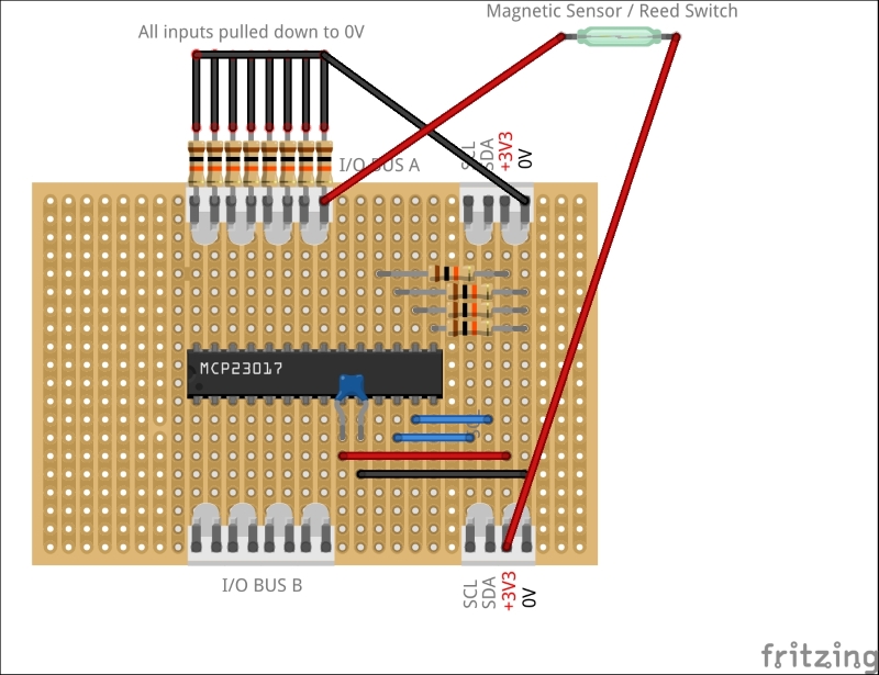
Let's go back to our port expander stripboard that was built in the previous chapter and connect our magnetic sensor. But first, we need to ensure that all of our inputs are pulled low by default using 10Kohm resistors. This prevents them from being in a floating state and giving us spurious data when we read the port's data.
To check the port's input value, we use the i2cget command:
$ sudo i2cget –y 1 0x20 0x12
This should return 0x00, which means all inputs are off (binary %00000000).
Now let's connect one side of our magnetic sensor's reed switch to data pin 0 of BUS A (which we'll call GPA0 for reference), and the other side to our +3.3V line. By default, the switch is normally open (NO), which means that the input is still pulled low by the resistor.
But when you move the accompanying magnet near to the sensor switch (for example, if the door is closed), the switch will close, pulling the input high to the +3.3V line. If you read the port's input value now, by running the same command, you should see that it returns 0x01, indicating that the first bit is high (binary %00000001).