Over the past eight chapters, we've explored the elements and concepts of a full-featured home security system that you'd expect to have installed in your property. It's been presented in a modular fashion so that you can choose which features you want for your system, to allow you to make it as compact and basic or large and complex as you require.
Fundamentally, the idea behind a home security system is to detect whether particular zone inputs are triggered high or low by an external sensor, be that a switch, motion detector, or water detector. At the end of the day, as far as the control software is concerned, the type of sensor is irrelevant and the system software's job is to simply check the state of its inputs and alert accordingly.
In this final chapter, we're going to put all of the concepts together to come up with a security system framework and write the control scripts around it. This is what we will cover:
- Defining a high-level overview of our system, detailing the connected elements
- Building the entire modular security system framework control script, exploring the code in detail
- Delving into some detailed shell scripting techniques to perform certain tasks
- Learning how to make our system automatically start at boot-time
- Preventing the burning out of our SD card by creating a RAM-based file system
So that we don't get lost in this process, the first thing I recommend is to come up with a complete system diagram that we can follow. I do this for any system I design and put together so that it can be built in a structured way, and easily documented and modified.
For the home security system in this chapter, I have come up with the following system diagram that we will look to as a framework. The whole concept is designed to be modular, so you can come up with your own system to suit your requirements and implement it accordingly, using the scripts presented in this chapter.
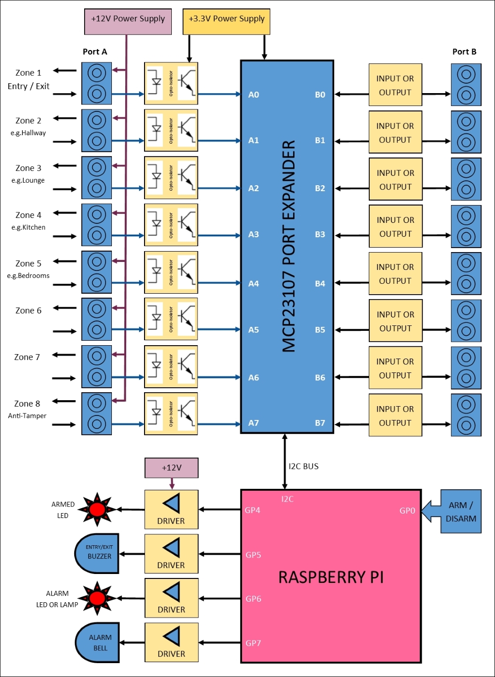
The final home security system diagram
The preceding system diagram comprises the elements and modules that we have discussed in previous chapters. Here's a quick recap of these:
This is the primary power supply to our system, which we will obtain from an external mains adapter that could be battery-backed. This supply needs to be smooth and regulated to ensure that it remains stable for the system as currently drawn.
All of the alarm wiring and sensors will be supplied with this power, as will peripherals such as sounders and bells, which usually operate from a 12V supply. Chapter 5, Adding a Passive Infrared Motion Sensor discussed the merits of using a 12V supply for the alarm circuits.
This supply is a regulated +3.3V supply for the digital port expander circuit; it also provides the logical alarm zone inputs via an opto-coupler. The +3.3V power supply can be derived from either the +12V supply (recommended), or the +5V supply from the Raspberry Pi's GPIO connector, using a voltage regulator chosen according to how much current you need.
Chapter 3, Extending Your Pi to Connect More Things, showed you how to build a +3.3V regulated supply.
This will isolate the +12V zone input power lines from the port expander and GPIO digital inputs, which should only have a maximum of +3.3V presented to them when triggered high.
The circuit for these opto-isolated input modules was discussed and shown in Chapter 5, Adding a Passive Infrared Motion Sensor.
The port expander is our main digital input/output system that will take the alarm zone inputs and transmit them to the Raspberry Pi using the I2C bus, or allow the Raspberry Pi to switch outputs on and off.
We built our MCP23017-based port expander circuit in Chapter 3, Extending Your Pi to Connect More Things and configured the software for it in Chapter 4, Adding a Magnetic Contact Sensor.
The arm/disarm input overrides the arm/disarm soft-switch function on our web-based control panel, and is a switch (key, digital keypad, or otherwise) connected to GP0 directly on the Raspberry Pi's GPIO connector.
Remember to connect any switch circuit appropriately to the GPIO pin to avoid damage to your Raspberry Pi. This was discussed in Chapter 2, Connecting Things to Your Pi with GPIO.
In our system, we have several output devices that are controlled by our Raspberry Pi via output driver circuits. We have an output for an entry/exit buzzer, an armed status LED, an alarm bell, and an alarm LED indicator.
These are switched on and off by our Raspberry Pi GPIO connector via driver circuits that allow us to drive high current and inductive loads using the GPIO pins. These driver circuits, based around TIP120 Darlington transistors, were discussed in Chapter 6, Adding Cameras to Our Security System and Chapter 8, A Miscellany of Things.