VLAN1
</objective> <objective>Access port
</objective> <objective></objective> <objective>Default route
</objective> </feature><feature><title>Concepts and Techniques You’ll Need to Master:</title> <objective>Using the Cisco SDM Express interface for initial router configuration
</objective> <objective>IP Subnetting
</objective> <objective>Using the Cisco SDM interface to configure NAT
</objective> <objective>Using the Cisco SDM interface to configure DHCP
</objective> <objective>Using the SDM interface to configure a default route
</objective> <objective>Testing and troubleshooting LAN and WAN connectivity
</objective> </feature>This chapter walks you through one of the tasks expected of a CCENT: Connecting a small office to the Internet. In our example, we will be using a Cisco 2821 router and a Catalyst 2960 switch, and our Internet connection will be an ADSL modem with an Ethernet interface we can connect the router to.
We will learn a few new things, but most of what you will see here are applied concepts that previous chapters have covered.
To set the stage for this exercise, assume that your head office has shipped a brand new router and switch to you. You have access to some guidance from your boss at the head office, a PC to work with, and all the cables and software you need. (I could make a joke here about this scenario not being very realistic, but that would be gratuitous.)
All right—let’s get started.
You have unpacked the router and switch and set them on your desk, ready to be plugged in.
New Cisco gear has a graphical user interface (GUI) that simplifies some of the more basic configuration tasks and provides useful dashboard views of the current status of the device. The software runs on the built-in web server on new devices and requires Internet Explorer and Java. You will also need to turn off pop-up blockers.
Your boss has sent you some useful information: This new router comes with a factory configuration that allows you to use the SDM right out of the box—it’s perfect for our scenario. When you use SDM for the first time on a router with factory-default settings, it starts with SDM Express, which is a quick-start GUI. We’ll use SDM Express to get to the full SDM. The email from your boss says to do the following to use the factory-configured SDM Express interface:
Connect a crossover cable from interface Gigabit 0/0 to your PC’s network interface card (NIC).
Statically set your PC’s IP address to 10.10.10.2 and the mask to 255.255.255.248.
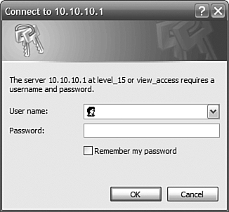
Point your web browser to http://10.10.10.1.
Figure 11.1 shows the results of this three-step operation.
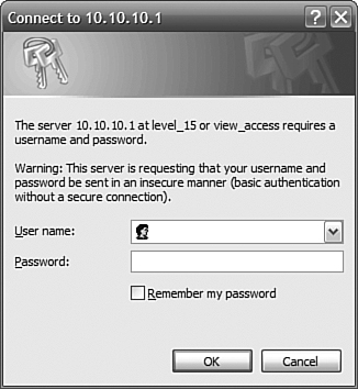
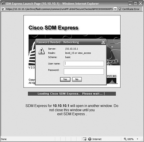
Your instructions say to use the username of cisco and the password cisco. Those are the defaults included from the factory to allow you to use the SDM interface. When you enter those, you are taken to the next screen, as shown in Figure 11.2.
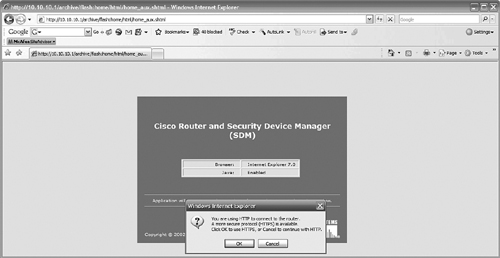
Choose HTTP for now. If the next screen warns about the website’s security certificate, click Continue to This Website. The next window (see Figure 11.3) is another login prompt; enter cisco and cisco again. Don’t worry, we’ll be changing these pretty soon!
Note
You really will need to disable any pop-up blockers, or the Java interface will not work. Along the same lines, whenever you get a security warning from the SDM router, it’s safe to allow access when your brand-new router is sitting on your desk, connected by a crossover cable. You may want to be more cautious when connecting to a router that is remote or that may have been compromised. For our purposes here, this kind of security is not a concern—yet.
You will probably get a couple security messages; it’s OK to allow access and run applications as long as you are in this lab context. Figure 11.4 shows yet another login screen. Use the same password again. Notice that this one is giving you level_15 access; that’s the same as Privileged EXEC.
Tip
You might find it confusing or even irritating that SDM prompts you for passwords so often. Unfortunately, it’s a function of the Java interface. There is a way around it, though: If you have a CCO login account, you can download and install a local copy of the Cisco ASDM Launcher, which replaces the Java interface and stops the duplicate login screens. It’s not strictly necessary, but it is useful.
After you press Enter, the SDM Express interface loads the router config, checks a couple things, and then presents you with the screen shown in Figure 11.5.
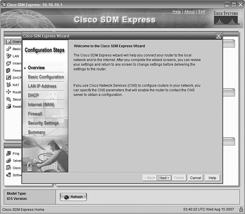
SDM Express is the name for a stripped-down SDM interface that asks you to configure the bare essentials to get your router working, addressed, using DHCP, and connected to the Internet —which is exactly what we want to do here. It also allows you to set up a router firewall, if your IOS version has the capability. That’s a little beyond what we want to do here, but I will say that in the real world you should never connect a router directly to the Internet unless it has a properly configured firewall protecting it!
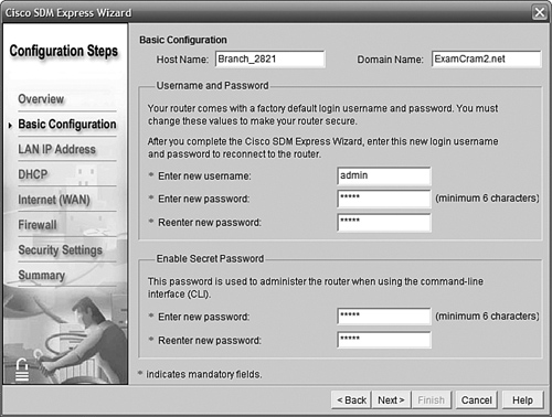
The first screen as shown in Figure 11.6 asks for the basics of the router hostname, the domain name, and new usernames and passwords. The hostname we’ll use is Branch_2821, the domain name will be ExamCram2.net, and we’ll use the username of admin and the password ciscocisco. (The SDM Express security requirements mandate a minimum six-character password.) We’ll use the same password for the enable secret as well, just to save confusion.
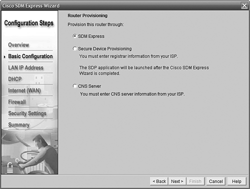
Clicking Next brings us to a screen that asks how we want to configure this router (see Figure 11.7). We’ll choose SDM Express and do it ourselves; the other choices are well beyond our scope but refer to methods of automated configuration in highly managed networks.
The next step is interesting. In it, we are going to change the IP address of the interface that we are actually connected to. That, of course, will break our connection, because we have to also change the address of the PC to match. It’s a bit of a cliffhanger—“Did I do it right?” Don’t panic. We always have the console cable.
Your boss has told you that this branch office LAN will use the last subnet created from 192.168.100.0/28. Because this is a new router, the zero subnets are available. The first IP address in this subnet will be assigned to the router.
Note
This router, a Cisco 2821, has two Gigabit Ethernet interfaces. Gi0/0 is factory configured with the IP address and mask that SDM uses. This will become our LAN interface. Gi0/1 will become our WAN (Internet) interface, but we will have the ADSL modem assign it a dynamic IP address using DHCP.
You didn’t think you were going to get away without subnetting, did you? Try and figure this out without cheating by reading ahead.
OK, for all you cheaters, here’s the solution:
192.168.100.0/28 uses an increment of 16 in the fourth octet. That means we will make 16 subnets from this Class C address, each of which has 14 host IPs available. (We get to keep all 16 subnets because the zero subnets are available.)
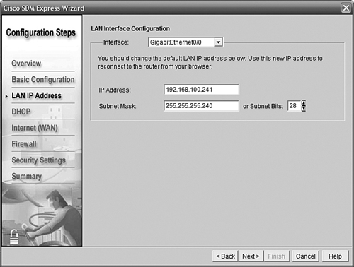
The first subnet is 192.168.100.0/28; the last one is 192.168.100.240/28. We can’t use the first and last IPs (.240 and .255) because they are reserved for the NetID and Broadcast ID. So, the first host ID, which we will give to our router, is 192.168.100.241/28. Notice that in the SDM interface shown in Figure 11.8, you can either type in the mask in decimal or just select the number of mask bits with the arrows.
The next screen deals with setting up this router to be a DHCP server. Remember that DHCP assigns IP addresses, subnet masks, default gateway, and several other options (for example, DNS server IPs) to hosts on the LAN. This is often a role assigned to a server on the LAN, but because our little branch office doesn’t have a server, we’ll take advantage of Cisco’s built-in DHCP service.
To configure the DHCP server, first click the check box that says Enable DHCP Server on the LAN Interface. (In the previous screen, we set Gi0/0 as the LAN interface by not choosing the LAN IP to be on some other interface.) We now have to specify what addresses the DHCP server should hand out by giving it a starting and ending range.
We need to remember that we must stay within the boundaries of our LAN subnet—but notice that SDM has already figured that out for us. By giving an IP address and mask to the LAN interface, SDM calculated our subnet IPs and starts with that whole range as its default. No cheating required!
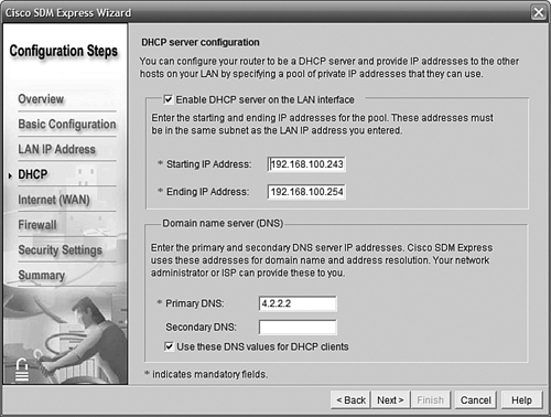
Often with DHCP we want to exclude certain addresses—such as the router itself, and maybe servers or printers that are already statically configured. In our case, we don’t have a server to worry about, but our switch will need an IP for management; we will give it 192.168.100.242/28. After taking the router’s Gi0/0 and the switch into account, that means we must start the range of DHCP addresses (called a scope) at 192.168.100.243; we can let it run all the way to the end of the subnet, to the last available IP of 192.168.100.254.
The ISP will advise us of the correct DNS server IP addresses. For the time being, we’ll use 4.2.2.2 in the first entry. Figure 11.9 shows the result.
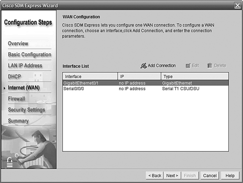
The next screen, shown in Figure 11.10, asks us to choose our WAN interface. You’ll notice that this router has discovered and listed two interfaces: GigabitEthernet0/1 and Serial0/0/0. The serial interface will be used at a later date for the planned VoIP implementation; the boss has asked us to leave it unconfigured for now. We have selected GigabitEthernet0/1 as our WAN interface; highlight it and click Add Connection.
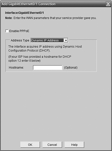
The window that comes up asks us to choose how our WAN interface will get its IP address; our choices are either Static IP Address or Dynamic IP Address. Static IP Address means we have to know what the IP and mask should be and set them manually (the ISP tells us this info). Dynamic IP Address means that we want the interface to get its IP automatically from the ADSL modem. We’ll choose Dynamic IP Address here; in the real world we might well choose Static IP Address if we wanted to access this router remotely or if there were servers in the office that we wanted to reach from the Internet. Usually we would need to specify in the ISP contract that we wanted one or more static IPs, and it might cost a little extra. Figure 11.11 shows the dialog box in action.
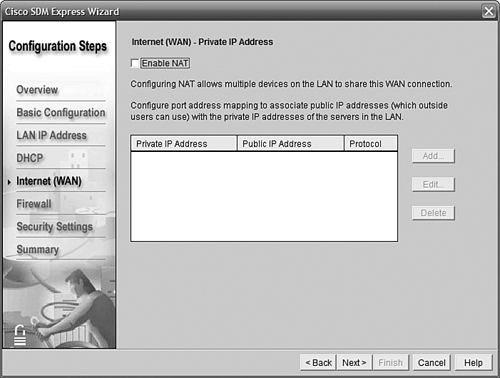
Network Address Translation (NAT) is a vital function for Internet-connected routers. The SDM Express NAT interface allows you to configure static NAT entries, but not NAT Overload (PAT). Because our exercise needs PAT and not a static setup, we’ll leave NAT disabled in the SDM for now. You can go back later and either use the command-line interface (CLI) or the full SDM interface (that is, not SDM Express) to configure it. Figure 11.12 shows the NAT screen with the Enable NAT box deselected.
SDM Express gives you the option to configure a firewall on the router (see Figure 11.13). SDM Express automatically creates a basic firewall that assumes one inside and one outside interface. Customizations can be made either from the full SDM version or preferably from the CLI.
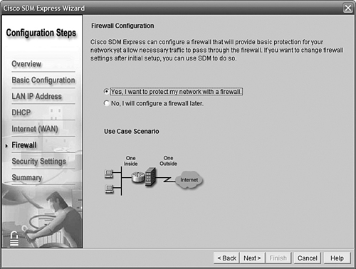
Firewall configuration is well beyond our scope, but we do want to emphasize the importance of a firewall associated with an Internet-connected router. If your IOS feature set does not support firewall functions, you will not be able to configure one on your router at all, and you should instead have an external firewall such as a Cisco Adaptive Security Appliance (ASA) or a device from another reputable vendor. We’ll point out the configurations that SDM Express added without delving into their meaning.
For now, we’ll let SDM Express do its thing by selecting Yes, I Want to Protect My Network with a Firewall, as shown in Figure 11.13.
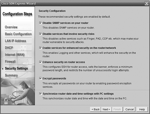
SDM Express can automatically prepare configurations for you that follow some of the best practices recommendations for securing a router. Many of the terms seen in Figure 11.14 will be familiar from Chapter 9, “Basic Network Security,” but some will be unfamiliar. We will leave the settings at their defaults (shown), but be aware that these settings will restrict how you can access the router (for example, requiring the use of SSH and strong passwords).
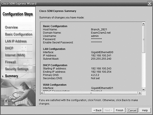
The screen in Figure 11.15 summarizes what we have told SDM Express to do. Here you can review your decisions, and you can click Back if you want to change anything.
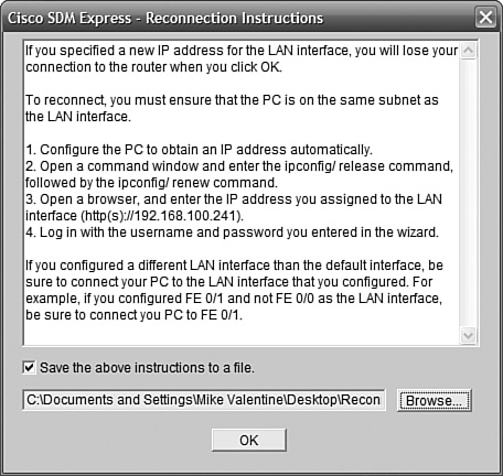
One of the scarier moments is when SDM reboots the router with its new config and you can’t connect to it anymore. You need to reconfigure your PC’s NIC to connect using the new settings; the screen shown in Figure 11.16 is popped up when you click Finished in the previous screen. It’s probably a good idea to save those instructions to a file by leaving the check box selected.
Because of the combination of settings we have chosen in SDM Express, the message shown in Figure 11.17 pops up. We will need to allow DHCP traffic, or else the Internet interface will not be able to get an IP address—the firewall basically prevents itself from doing so!
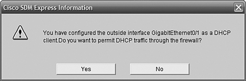
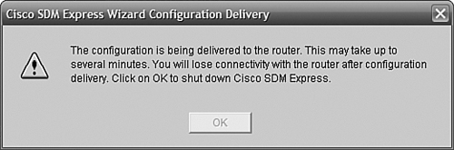
Figure 11.18 shows our “last warning” before the SDM configuration is applied and we lose connectivity. Clicking OK closes the SDM and Internet Explorer windows, and as the IP address of the web interfaces changes, connectivity to the router is (temporarily) lost.
When you have reconfigured your PC’s NIC as instructed by SDM, go to the address https://192.168.100.241 (this is the address in our exercise—obviously it could be different in your lab or reality!) We have specified the use of HTTPs, which is supported as a security option by SDM (as shown in Figure 11.16), but we could use HTTP instead.
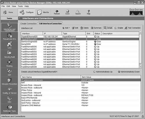
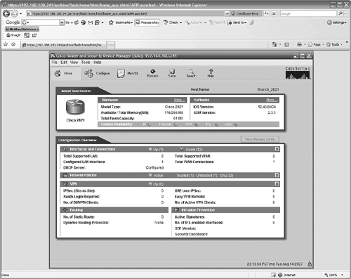
Figure 11.19 shows the SDM home page after you have logged in (using the new username and password we specified) and accepted the same security warnings we saw before. Remember to disable pop-up blockers, or at least allow pop-ups from the new address of the router.
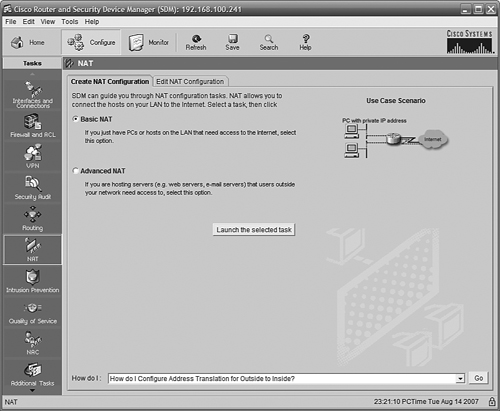
We still need to set up Overload NAT and a default route; we can use the SDM interface to do this (SDM Express does not have this advanced capability). In Figure 11.20, we have clicked first on the Configure button at the top of the page; then when the page changed, we clicked NAT in the column on the left. We will configure Basic NAT because we do not need to specify servers and applications that must be reachable. Clicking the Launch the Selected Task button starts the Basic NAT Wizard.
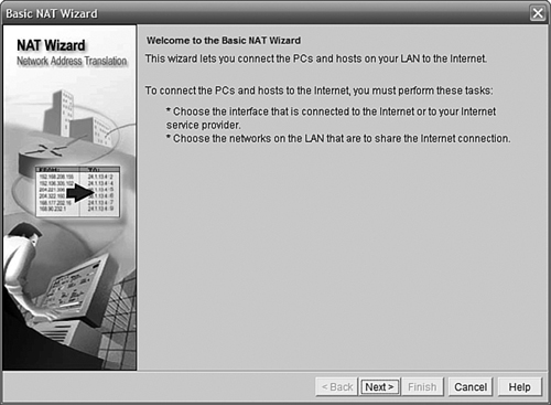
The Basic NAT Wizard (see Figure 11.21) walks you through the configuration of Overload NAT on the router.
In Figure 11.22 we have selected the GigabitEthernet0/1 interface as our Internet interface (because it is) and selected the network that will be NATed to that interface.
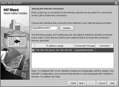
Figure 11.23 shows us the Finish screen of the Basic NAT Wizard and the settings we have selected.
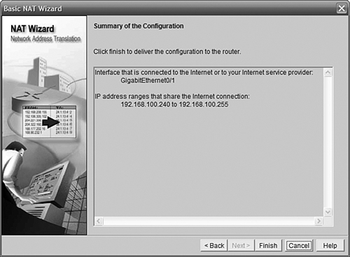
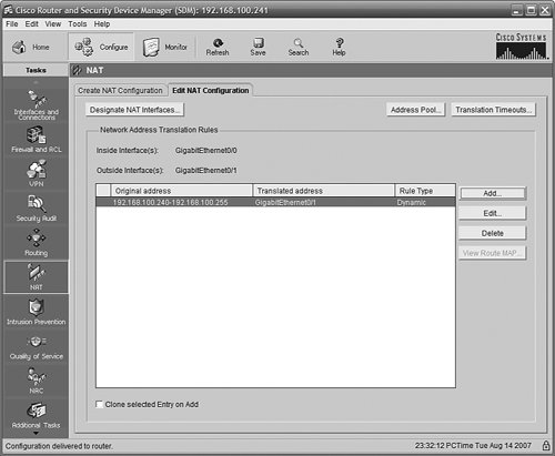
Figure 11.24 shows the updated SDM NAT page after our changes.
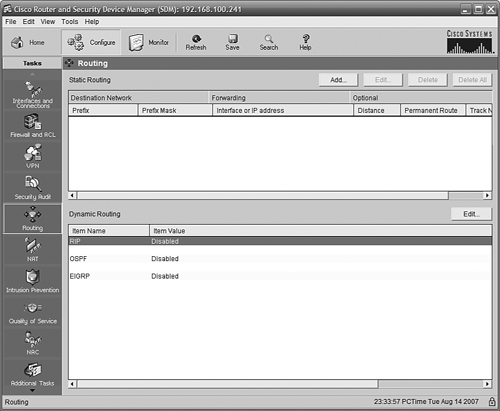
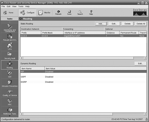
Our connection is almost ready. One thing left to do is to define a default route out to the Internet. Using the SDM interface, click Routing in the column on the left. The page shown in Figure 11.25 is displayed. There are no routes listed.
Clicking Add near the top pops up the route configuration dialog box. In Figure 11.26, we have chosen to create a default route by specifying the network 0.0.0.0, the mask 0.0.0.0, and selecting the Make This as the Default Route check box. We also specified GigabitEthernet0/1 as the next-hop interface because this is our Internet interface. If we were using a static IP from our ISP, we would specify the IP instead. I chose to check the Permanent Route box so that the route would stay in the route table even if the next hop is unavailable.
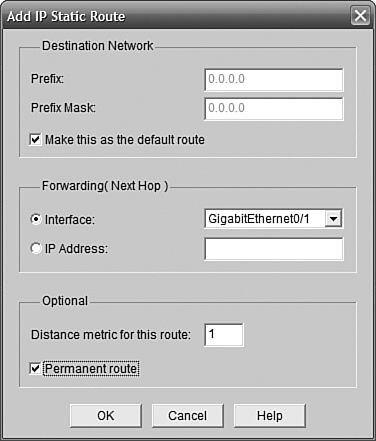
Figure 11.27 shows the Routing page after our update. The default route is shown.
The SDM interface includes some very useful tools to check your connectivity. From the SDM home page, click the Monitor button near the top. Then click Interface Status on the left.
Near the top of the main pane in the screen is a list of interfaces. Click the Internet interface (in our case, GigabitEthernet0/1) to highlight it. Then, click the Test Connection button at the top right. Figure 11.28 shows the page that comes up when you do so.
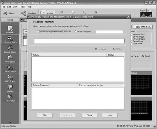
You have the option of letting SDM choose a host to ping, or you can specify one. Clicking Start at the bottom of the page starts a series of tests, and lists what the outcome was, as shown in Figure 11.29.
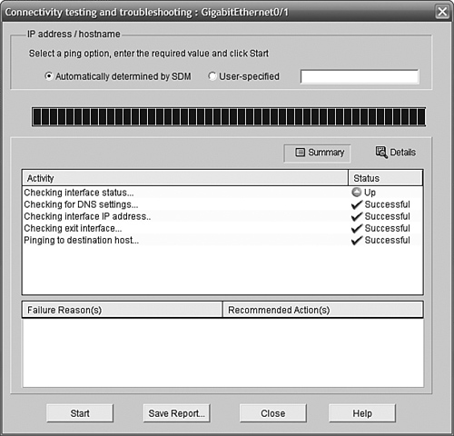
You can click the Details button to see the specifics of what was tested.
Let’s take a quick look at the DHCP configuration page in SDM to see the result of what we did in SDM Express. From the SDM home page, click Additional Tasks in the left (Tasks) pane. In the middle pane, click the plus sign to expand DHCP. Next, click DHCP Pools in the expanded list. Figure 11.30 shows the resulting view.
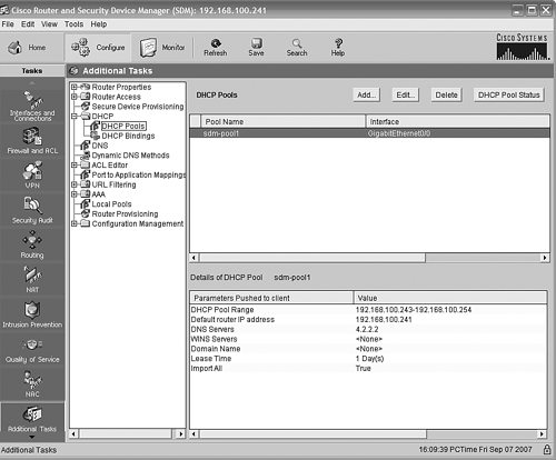
We can see that the pool named sdm-pool1 is associated with Interface GigabitEthernet0/0, and the details of the pool correspond to what we entered into SDM Express earlier.
That is pretty much all we need to do with the router. Now let’s turn our attention to the switch.
Our switch is a new Catalyst 2960, with 24 10/100 Ethernet ports and two 10/100/1000 Ethernet ports. We will configure our switch from the CLI. We need to give the switch a management IP address and a default gateway; we also want to apply passwords and restrict remote access to Secure Shell (SSH). We will leave all interfaces in VLAN1 for now; more advanced configurations will be made later.
Plug in your console cable and make sure your terminal application is configured properly as follows:
9600 baud
8 data bits
1 stop bit
No parity
Flow control = Off
Because this is a new switch, we will be prompted to enter the Initial Configuration dialog; we can bypass this and go straight to the command line. By default, there is no password to enable the switch.
We are going to configure some basic security on the switch. Our first tasks are the following:
Set the hostname to
Branch_2960:Switch>enable Switch#config t Switch(config)#hostname Branch_2960 Branch_2960(config)#
Configure a console password of
ciscocisco:Branch_2960(config)#line con 0 Branch_2960(config-line)#password ciscocisco Branch_2960(config-line)#login Branch_2960(config-line)#
Configure a VTY line password of
ciscociscoon the first five VTY lines.Restrict access to the VTY lines to SSH only.
To complete tasks 3 and 4, we need to go back to the Global Config prompt. SSH requires a hostname (we already set one), a domain name, and the generation of an RSA keypair. We will also create a username and password for local authentication. Then we will go back to the VTY lines and require a password to log in, configure the switch to use the username and password we gave it, and further restrict the VTY lines to SSH only.
Branch_2960(config-line)#exit
Branch_2960(config)#ip domain-name ExamCram2.net
Branch_2960(config)#crypto key generate rsa
Branch_2960(config)#username admin password ciscocisco
Branch_2960(config)#line vty 0 4
Branch_2960(config-line)#login
Branch_2960(config-line)#login local
Branch_2960(config-line)#transport input ssh
Branch_2960(config-line)#exit
Branch_2960(config)#
Set an encrypted Privileged EXEC password of
ciscosecret:Branch_2960(config)#enable secret ciscosecretEncrypt console and VTY line passwords:
Branch_2960(config)#service password-encryption
Setting the management IP on a switch involves configuring a VLAN interface. A Layer 2 switch such as the 2960 will support one VLAN interface at a time; the default is to use interface VLAN1.
Note
Many students seem to have trouble grasping the difference between a VLAN and VLAN interface. A VLAN divides a switch, at Layer 2, into separate broadcast domains. Switch ports are assigned to VLANs. A VLAN interface is a virtual (software) interface that will accept an IP address and mask, and it is the only place on a Layer 2 switch you can assign an IP. VLAN1 is the default ethernet VLAN; interface VLAN1 is the default VLAN interface and is usually the one used for managing the switch remotely.
To set the management IP on interface VLAN1, the commands are
Branch_2960(config)#interface vlan1
Branch_2960(config-if)#ip address192.168.100.242 255.255.255.240
Branch_2960(config-if)#no shut
Branch_2960(config-if)#exit
Branch_2960(config)#
Setting the switch’s default gateway allows the switch to send packets destined for any subnet that is not on its VLAN1 subnet to our router, which can then route the packet wherever it needs to go. A single command will do this:
Branch_2960(config)#ip default-gateway 192.168.100.241That completes the switch configuration, At this point, to test whether it is all working, you can perform the classic troubleshooting methodology:
Plug in a PC to the switch; make sure the PC is set to use DHCP.
Check that link lights are lit on the switchport and PC NIC.
If this step fails, check your cables and connections.
Check that PC obtains an IP address and mask in the expected subnet from DHCP.
If this step fails, try the command
ipconfig /renewfrom the command prompt on the PC. If it still will not get an IP address, make sure that the connection to the router is working and verify that the DHCP server on the router is active. You may also want to try disabling and reenabling the PC NIC.On the PC, ping its own IP address.
If this step fails, there is a problem with the PC’s NIC. Try replacing it, or try a different PC.
On the PC, ping the router’s IP address.
If this step fails, check that the router’s interface is up/up and that the IP address is correct.
On the PC, ping an Internet IP address.
If this step fails, check the default route. Ensure that the Internet interface is up/up and that the Internet connection is working properly.
That is all we really need to do to set up and test a small office Internet connection. There are, of course, many more advanced configurations that might be required, depending on the circumstances.