VTP Server, Client, Transparent
</objective> <objective>VTP Domain
</objective> <objective></objective> <objective></objective> </feature><feature><title>Concepts and Techniques You’ll Need to Master:</title> <objective>Identifying the Root switch in a system
</objective> <objective>Identifying Root, Designated, and Blocked ports in a system
</objective> <objective>Creating and naming VLANs
</objective> <objective>Assigning switch ports to VLANs
</objective> <objective>Configuring trunk links
</objective> <objective>Creating and joining a VTP domain
</objective> <objective>Troubleshooting VTP and Inter-VLAN routing
</objective> </feature>This chapter introduces the Spanning Tree Protocol (STP) and reviews some of its enhanced features. We then move into the theory, benefits, applications, and implementation of VLANs. Inter-switch connectivity using trunks and the characteristics of different trunking protocols are explained. Finally, Inter-VLAN routing options are described, and troubleshooting tips are reviewed.
Earlier, we mentioned that one of the functions of a switch was Layer 2 loop removal. This is a critical feature, as without it many switched networks would completely cease to function. Either accidentally or deliberately in the process of creating a redundant network, the problem arises when we create a looped switched path. A loop can be defined as two or more switches that are interconnected by two or more physical links.
Switching loops create three major problems:
Broadcast storms—. Switches must flood broadcasts, so a looped topology will create multiple copies of a single broadcast and perpetually cycle them through the loop.
MAC table instability—. Loops make it appear that a single MAC address is reachable on multiple ports of a switch, and the switch is constantly updating the MAC table.
Duplicate frames—. Because there are multiple paths to a single MAC, it is possible that a frame could be duplicated to be flooded out all paths to a single destination MAC.
All these problems are serious and will bring a network to an effective standstill unless prevented.
Figure 12.1 illustrates a looped configuration causing a broadcast storm.
Other than simple error, the most common reason that loops are created is because we want to build a redundant or fault-tolerant network. By definition, redundancy means that we have a backup, separate path for data to follow in the event the first one fails. The problem is that unless the backup path is physically disabled—perhaps by unplugging it—the path creates a loop and causes the problems mentioned previously. We like redundant systems; we do not like loops and the problems they cause. We need a mechanism that automatically detects and prevents loops so that we can build the fault-tolerant physical links and have them become active only when needed. The mechanism is called the Spanning Tree Protocol (STP). STP is a protocol that runs on bridges and switches to find and block redundant looped paths during normal operation. Spanning Tree was originally developed by the Digital Equipment Corporation (DEC), and the idea was adopted and modified by the IEEE to become 802.1d. The two are incompatible, but it is exceedingly rare to find a DEC bridge these days, so the incompatibility is not usually a problem.
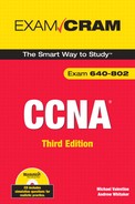
STP’s basic function is to create a loop-free path to a root bridge. The root bridge is the bridge or switch that is the root of the Spanning Tree, with the branches being loop-free paths to the other switches in the system. The Root is the switch with the lowest Bridge ID; the ID is determined by a combination of an administrative Priority and the MAC address of the switch. The Priority is set to 32,768 (8000 hex) by default; if we leave the Priority at the default, whatever switch has the lowest MAC will be the Root. Figure 12.2 illustrates a simple Root selection when all switches are using the default Priority.
We cannot change the MAC address of a switch, so what happens if Switch A in the previous example happens to be an old, slow Catalyst 1900? It might get elected the Root because it has a low MAC address, but we really don’t want it to be the Root: Usually, we would choose a big, fast switch at the core of the network as the Root. Let’s say that Switch C is a hot new switch and we want it to be our Root; how do we override the existing election? The answer is to change the default Priority—remember, the lowest ID wins the election, and the ID is the Priority prepended to the MAC. The ID is one long string, so lowering the Priority makes the ID lower. Thus, if we change the Priority of Switch C to a low value, it will win the election despite the fact that it has a higher MAC than A. Figure 12.3 illustrates this.
To determine the presence of loops and to block loops, switches must be capable of communicating with each other about the various connections they have. This communication in STP is carried out by the exchange of Bridge Protocol Data Units (BPDUs). The 802.1d BPDU is multicasted every two seconds and includes information the switches need to decide if there are loops, how to fix them, and which switch is the Root. Figure 12.4 shows the fields in an 802.1d BPDU; note the fields for the Bridge ID, the Root ID, and the Root Path Cost.
STP assigns different ports on a switch as different types, depending on where the Root is and where the loops are in the topology. The sections that follow describe the port types and how they are selected.
The Root port on a switch is the one port that has the lowest cost path to the Root switch. Path cost is calculated based on the bandwidth of the links. Table 12.1 lists the IEEE-defined values for STP path cost; note that there are old and new values. The new values were defined because of the increasingly widespread availability of multi-Gigabit link speeds; previously, a 1Gbs link had the same cost as a 10Gbps link. That made no sense and would create suboptimal STP topologies, so the costs were revised.
After the switches have elected the Root for the system, each switch must then decide which port it will use to reach the Root. Some switches will have only one port that can reach the Root at all; some might have several, depending on the number and location of uplinks between the switches in the system. The exchange of BPDUs that decides the Root election also tells each switch about the path costs to reach the Root (as indicated by the value of the Root Path Cost field in the BPDU). Each switch adds its own path cost to the path cost received from the neighboring switch and chooses the port with the lowest cost as the Root port. Figure 12.5 illustrates root port selection in a simple switched network.
Note that the Root itself does not have any Root ports: It does not need to reach the Root—it is the Root!
For each LAN segment, there must be one Designated port. This is the port that will forward traffic to the Root from the LAN segment. The Designated port is the port that has the least cost path to the Root from the LAN segment.
The Root switch has only Designated ports. Because it is the root, it won’t have a Root port, and it can’t block any of the ports that connect to other switches (because that would make the other switch’s Root ports not work).
In Figure 12.6, our three switches have already elected the Root and chosen their Root ports. Switch A is the Root, so all of its ports are Designated. Switches B and C must next choose which port will block and which port will be designated on the link between them.
The first criterion examined is which switch has the lowest Root Path Cost. In our setup here, B and C each connect to the Root with a 100Mbps connection, with an STP cost of 19. By examining each other’s BPDUs, B and C realize that they are tied for Root Path Cost.
This is a very common scenario in modern networks where switches are directly connected over full-duplex crossover cables. One of the switches must block its port to stop the loop. The second criterion (the first tiebreaker) is the lower Bridge ID: In this case, Switch B wins and Switch C must block its port.
As we get into more complex switched systems, we get into situations where additional criteria (tiebreakers) are needed. The full list is examined in the next section, “Port Type Selection.”
The order of criteria a switch goes through when deciding its Root and Designated ports is as follows:
The port with the lowest cumulative Root Path Cost will be the Root port/Designated port.
If tied between multiple ports, the port that connects to the neighboring switch with the lowest Bridge ID becomes the Root port/Designated port.
If there are multiple connections to that same switch, the port with the lowest assigned STP priority will be the Root port/Designated port.
If tied, the port with the lowest hardware number (Fa0/1 is lower than Fa0/2) will be the Root port/Designated port.
A Blocked port is neither the Root port nor the Designated port, but is part of the redundant links between switches. In other words, it lost in the election to choose the active Root or Designated ports, but it might take over one of these roles if the active port failed. A Blocked port is the one that actually stops the loop, so it is just as important as the Root or Designated. A Blocked port does not send data; it only receives BPDUs.
Convergence is the term used to describe the process STP goes through to achieve a stable, loop-free network. (The same term is used with reference to routing information stability as well.) When all switches have elected the Root and decided on their Root, Designated, and Blocked ports, the system is said to be converged.
With 802.1d STP, each port on each switch goes through four distinct port states in the process of convergence:
Blocking—. When a switch boots up, all ports start in the Blocking state. This is to prevent loops during the time that the STP topology is converging. A port that is a link between switches will stay blocked unless it becomes a Root or Designated port. Blocked ports send no data at all (not even BPDUs), but they do listen for (receive) BPDUs from other switches. All ports will also go to Blocking mode if a Topology Change Notification (TCN) BPDU is received. TCNs are issued when a new link is added or removed—the topology of the switched system is altered. When this happens, STP reacts by blocking all ports until loop-free convergence is achieved.
If a switch dies or a link between switches fails, the other switches connected to it wait for a specific time until they begin the STP convergence process. This interval is called the Max Age Timer, and by default it is 20 seconds. Effectively, it means that a switch will wait until it has missed 10 BPDUs (which are sent every 2 seconds) from a connected switch before it kicks in the STP recalculation.
Listening—. The Listening state enables a Blocked port to begin sending its own BPDUs. By default, the Listening state is 15 seconds.
Learning—. The Learning state is when the switch begins populating its MAC address table. It is not yet forwarding any frames, but it is getting ready to forward by building as complete a MAC table as it can. The Listening state is also 15 seconds by default. The Listening and Learning states together are called the Forward Delay, and you might see their two 15-second timers represented as a single 30-second timer called the Forward Delay Timer.
Forwarding—. The Forwarding state, as its name implies, is when the port starts forwarding frames. This is simply normal operation for a port that is not blocked.
If you take a quick look at these states and their timers, you can see that in 802.1d STP, reaching convergence can take anywhere from 30 to 50 seconds (Forward Delay [15+15]+ MaxAge[20] = 50 seconds). Understand that during this 30 to 50 seconds, no frames are being forwarded at all—no data is being sent anywhere because every port on every switch is either Blocking, Listening, or Learning. This is, of course, very detrimental to the productivity and utility of a network, especially a modern, busy one. A 50-second delay every time a topology change happens is unacceptable, so Cisco (and then the IEEE) created several enhancements to 802.1d STP to speed up the process of convergence. Some of these enhancements are discussed in the following section.
The Rapid Spanning Tree protocol (RSTP, IEEE 802.1w—remember, 802.1w is Wapid Spanning Twee) has many of its roots in Cisco-created enhancements to ordinary 802.1d STP. The primary goal of these enhancements is to speed up convergence. There are no timers in RSTP; instead, the BPDU becomes much more detailed and informative so that switches can gather more information with greater accuracy. New port states have been defined as shown in Table 12.2.
Switches wait for only three missing BPDUs before commencing the Spanning-Tree recalculation process. The process of convergence is itself much more rapid because new port types have been defined as well. In addition to the Root and Designated port types in STP, RSTP defines the Alternate and Backup port types. The Alternate port is the port that will become the Root port if the primary Root port fails. The Backup port is the port that will become the Designated port if the primary Designated port fails. The BPDUs in RSTP convey information about these port types to neighboring switches. This enhanced communication allows for quicker convergence, without relying on the 30–50 second timers in STP.
Another significant improvement in convergence speed comes from the Rapid Transition to Forwarding (RTF) features of Edge ports and link types. Edge ports are ports that are connected to non–STP-capable devices such as PCs, servers, or routers. These devices will not normally create STP loops, so there is no need for them to block to prevent loops. This function is enabled by Cisco’s portfast command feature. With PortFast configured, a switch port will stop sending BPDUs (after a few have been sent as a precaution to prevent loops) and transition to the forwarding state almost immediately. This is very useful to get frames moving through the switch so hosts can get on with business—picture a database server and a PC connected to the same switch; they would not have to wait the 50 seconds for STP convergence if PortFast was configured on both ports. In addition, if a port configured for portfast does receive a BPDU (perhaps because someone plugged a switch in), by default it will disable PortFast and start STP on that port to prevent loops. You can also optionally configure the switch port with BPDU Guard to shut down the port if it receives a BPDU. This is more secure because it prevents the unauthorized installation of switches. BPDU Guard is covered in the Cisco CCNP curriculum.
The interface-configuration syntax to configure a Catalyst switch port with PortFast looks like this:
Switch(config-if)#spanning-tree portfastOr, to set all ports to use portfast by default, use the global configuration command:
Switch(config)#spanning-tree portfast defaultTo turn PortFast off, use the spanning-tree portfast disable interface configuration command.
Another Cisco enhancement deals with port security; this feature set allows you (among several other options) to disable a port if more than one MAC address is detected as being connected to the port. This feature is commonly applied to ports that connect security-sensitive devices such as servers.
The following command syntax restricts access to a single MAC address and shuts the port down if another MAC connects:
Switch(config)#interface fa0/21
Switch(config-if)#switchport mode access
Switch(config-if)#switchport port-security
Switch(config-if)#switchport port-security maximum 1
Switch(config-if)#switchport port-security violation shutdown
Link Types refers to a port setting of either full duplex or half duplex. If a port is set for full duplex, RSTP assumes that it is a candidate for rapid transition because there can be only one other device at the end of such a connection. If it is set for half duplex, however, it is conceivable that there could be multiple STP-capable devices on that segment, so by default the RTF functions are disabled. It is possible to override this default.
When you plug a bunch of PCs in to a switch and give them all IP addresses in the same network, you create a LAN. A VLAN is a virtual LAN. The difference is that with VLANs, you still connect all the PCs to a single switch but you make the switch behave as if it were multiple, independent switches. Each VLAN is its own broadcast domain and IP subnet. In this way, you get the ability to use switches to segment broadcast domains, which up to this point was possible only with routers. Figure 12.7 illustrates a simple VLAN configuration:
A VLAN can be defined as a virtual broadcast domain. Instead of segmenting the broadcast domain with routers at Layer 3, you segment using switches at Layer 2. Each VLAN should be associated with its own IP subnet. (No, this is not technically a requirement, but you really want to do it this way!)
The advantages of using VLANs are as follows:
VLANs increase the number of broadcast domains while reducing their size; this is the same effect that routers have, but without the need to buy a lot of routers or a big router with a lot of ports, so it’s less expensive and easier to administer.
VLANs provide an additional layer of security: No device in any VLAN can communicate with a device in any other VLAN until you deliberately configure a way for it to do so. An example might be a server in VLAN 10 that holds sensitive employee files for HR; no PCs from other VLANs can access VLAN 10 (or the server in it), unless you specifically configure it to do so.
VLANs are flexible in terms of how they are used in network equipment: Imagine a building that has LAN cabling and a single switch installed, but four different tenants. You can create four different VLANs, one for each tenant, and no tenant will see or hear from the other tenants on the other VLANs.
VLANs can span across multiple switches using trunk links. This allows you to create a logical grouping of network users by function instead of location. If you want all the marketing people to be in their own broadcast domain and IP subnet, you can create a VLAN for them on the first switch; then, you can connect another switch using a trunk link, define the same VLAN on that switch, and the marketing users on the second switch are in the same VLAN and can communicate with the marketing users on the first switch, and are isolated from other VLANs on both switches. This capability can be extended across an enterprise network campus, so that marketing users in the Whitaker Pavilion could in theory be in a VLAN with other marketing users in the Valentine Pavilion.
The ability to trunk VLANs across multiple switches makes adding users, moving users, and changing users’ VLAN memberships much easier.
Exam Alert
Increase the number of broadcast domains while reducing their size.
Provide additional security.
Increase the flexibility of network equipment.
Allow a logical grouping of users by function, not location.
Make user adds, moves, and changes easier.
Figure 12.8 illustrates a multi-switch VLAN system.
Implementing VLANs is done in three steps:
The commands to create a VLAN vary depending on the switch model and IOS version; we stick with the Catalyst 2960 using an IOS later than 12.1(9) as our example.
The command to create a VLAN is simply vlan [vlan_#]. To name the VLAN, the equally simple command is name [vlan_name]. These commands are entered starting at the global config prompt.
To create VLAN 10 named HR, VLAN 20 named Marketing, and VLAN 30 named Engineering, the commands look like this:
2960#configure terminal
2960(config)#vlan 10
2960(config-vlan)#name HR
2960(config-vlan)#vlan 20
2960(config-vlan)#name Marketing
2960(config-vlan)#vlan 30
2960(config-vlan)#name Engineering
2960(config-vlan)#exit
2960(config)#exit
2960#
The global config prompt changes to the config-vlan prompt when you create the first VLAN; it is okay to stay in that prompt to continue creating VLANs.
With these commands, you can create all your VLANs at once, or you can go back later and add some more as needed. The VLAN configuration (names and numbers) is not stored in the running-config or startup-config file in NVRAM; rather, it is stored in flash memory in a special file called vlan.dat. This means that it is possible to erase the startup-config file, reload the router, and be confused by the reappearance of VLANs that you thought you just deleted. To delete VLANs, you can do it one at a time using the no vlan [vlan_#] command, or to get rid of all of them at once, you can use the command delete flash:vlan.dat, which erases and resets the entire VLAN database.
Caution
The exact syntax for the delete flash:vlan.dat command is critical: no space after flash or the colon! If you put a space after flash, you could delete the entire flash directory, including your IOS. This is a very bad thing to do, and is actually quite an ordeal to fix.
Note
Cisco switches have a few default VLANs preconfigured; these are intended for the management and essential functionality of Ethernet, Token Ring, and FDDI LANs. VLAN 1, for example, is the management VLAN for Ethernet. All switch ports are in VLAN 1 by default. You cannot change or delete these default VLANs.
The Cisco Catalyst 2960 will support up to 1005 VLANs defined locally.
VLANs can exist without any ports actually being in them. Adding switch ports to a VLAN is done when you want to put a host into a particular VLAN. Obviously, you need to know which physical ports your hosts are connected to so that you can add the correct port to the correct VLAN; it would be an unpopular move to put a marketing user into the Engineering VLAN; these two groups are mutually hostile.
The commands to add a switch port to a VLAN are executed at the Interface Config prompt—if you think about that, it makes sense because you are putting the port itself into the VLAN. The command is switchport access vlan [vlan_#]. What you are saying is “this port shall access VLAN X.”
The following example puts ports Fa0/8 into VLAN 10, Fa0/13 into VLAN 20, and Fa0/14 into VLAN 30:
2960#config t
2960(config)#interface fa0/8
2960(config-if)#switchport access vlan 10
2960(config-if)#int fa0/13
2960(config-if)#switchport access vlan 20
2960(config-if)#int fa0/14
2960(config-if)#switchport access vlan 30
2960(config-if)#exit
2960(config)#exit
2960#
The commands in the previous section assign particular ports to a particular VLAN statically. (Static VLAN assignment is sometimes called port-based VLAN membership.) When a user changes ports (moves around the office or campus), you need to repeat the commands at the Switch(config-if)# prompt for the correct new interface. As you can imagine, if there are a lot of moves, this can become an administrative pain.
There is an alternative called dynamic VLAN membership. This feature allows you to dynamically assign VLAN membership to switch ports based on the MAC address of the host connecting to the port. You need a little service called the VLAN Membership Policy Server (VMPS) that holds a database of all the MAC addresses and the correct VLAN for each one; then you tell the switch ports to do dynamic VLAN assignment. When a host connects to a switch port configured to do dynamic membership, the switch checks the MAC of the host and asks the VMPS what VLAN that MAC should be in. The switch then changes the VLAN membership of that port dynamically.
This sounds like a wonderful idea, and it can be, but it is difficult to create the VMPS database and to maintain it if your network grows quickly. Imagine having to get and maintain certain knowledge of every MAC address of every host in your network, and then keep the VMPS database updated. Dynamic VLAN membership is a good option if you have a lot of users in a lot of different VLANs moving around to many switch ports, but be ready to wrestle with some administrative issues.
For VLANs to span across multiple switches, you obviously need to connect the switches to each other. Although it is possible to simply plug one switch into another using an Access port just as you would plug in a host or a hub, doing so kills the VLAN-spanning feature and a bunch of other useful stuff too. A switch-to-switch link must be set up as a trunk link in order for the VLAN system to work properly. A trunk link is a special connection; the key difference between an ordinary connection (an Access port) and a Trunk port is that although an Access port is only in one VLAN at a time, a Trunk port has the job of carrying traffic for all VLANs from one switch to another. Any time you connect a switch to another switch, you want to make it a trunk.
Some key points about trunks are as follows:
A trunk can be created only on a Fast Ethernet or Gigabit Ethernet connection; 10Mb Ethernet ports are not fast enough to support the increased traffic from multiple VLANs, so the commands are not available for a regular Ethernet port.
By default, traffic from all VLANs is allowed on a trunk. You can specify which VLANs are permitted (or not) to cross a particular trunk if you have that requirement, but these functions are beyond the scope of the CCNA exam.
Switches (whether trunked or not) are always connected with crossover cables, not straight-through cables. In CCNA land, there is no such thing as a “smart port” that will auto-detect a crossed connection and fix it. The Catalyst 2960 has such a feature, but the exam will test your knowledge of when to use a crossover cable. For the purposes of your exams, if two switches are not connected with a crossover cable, there will be no connectivity between them, period.
Exam Alert
By default, all VLANs are permitted across a trunk link. Switch-to-switch trunk links always require the use of a crossover cable, never a straight-through cable.
When creating a trunk, you must choose a trunking protocol. A trunking protocol adds a VLAN identification tag to frames coming into the switch. As those frames are forwarded across the trunk, the VLAN from which the frame originated is identifiable, and the data frame can be distributed to ports in the same VLAN on other switches—and not to different VLANs. This frame tagging and multiplexing function is what enables VLANs to span multiple switches and still keeps each VLAN as a separate broadcast domain. Figure 12.9 illustrates a simple trunk as it multiplexes frames from two separate VLANs across a single Fast Ethernet Trunk.

Cisco supports two trunking protocols, ISL and 802.1Q, as described in the next sections.
The Inter-Switch Link (ISL) protocol is a Cisco-proprietary Layer 2 protocol. ISL operates by re-encapsulating host frames as they are received by the switch port. The ISL encapsulation adds a 26-byte header and a 4-byte trailer to the original host frame. The header includes the VLAN ID (the VLAN number) and several other fields. The trailer is a new CRC to check the integrity of the ISL frame.
There are two significant issues with ISL. The first is that it is Cisco proprietary, meaning that it will work only between two Cisco devices. In a perfect world, of course, everyone would have all Cisco gear, but the reality is a lot of non-Cisco network devices are out there. To complicate matters, Cisco has begun to phase out ISL in favor of 802.1Q; for example, the Cisco 2960 does not support ISL at all, only 802.1Q.
The second issue with ISL is frame size. If a frame is received that is already at the MTU, the addition of the 26-byte header and 4-byte trailer can create frames that are over the Ethernet MTU of 1,518 bytes (with ISL encapsulation, now at 1,548 bytes), which will be dropped as “Giant” frames by devices that do not recognize the ISL encapsulation. Figure 12.10 illustrates an ISL-encapsulated frame.
The IEEE-standard 802.1Q trunk encapsulation has the advantage of being an industry standard, so inter-vendor operation is much less of a problem. Often referred to as “dot1q” (because geeks like lingo), this protocol does not re-encapsulate the original frame, but instead inserts a 4-byte tag into the original header. This means that a dot1q frame will be seen as a “baby giant” of 1,522 bytes. Most modern NICs will not reject these frames if they mistakenly receive one. Figure 12.11 shows a dot1q-tagged frame.
Configuring a switch for trunking is fairly straightforward. Once again, we focus on the Catalyst 2960 switch; other switches have slightly different capabilities and syntax, and special note of this is made when necessary.
Note
Cisco has implemented the Dynamic Trunking Protocol to make setting up trunks easier. DTP can send and/or receive trunk negotiation frames to dynamically establish a trunk link with a connected switch. DTP is not necessary to establish a trunk link, and like many other automatic functions, many administrators would rather not use it and instead manually configure their trunk links. The CCNA exam is not concerned with DTP, but does ask about the five port modes, so an explanation is warranted.
A switch port can be in one of five modes:
Off—. In Off mode, the port is an Access port and will not trunk, even if the neighbor switch wants to. This mode is intended for the connection of single hosts or hubs. DTP frames are not sent or acknowledged. The command to enable this is
switchport mode access.On—. In On mode, the port will trunk unconditionally, and trunk connectivity will happen if the neighbor switch port is set to Auto, Desirable, or NoNegotiate. DTP frames are sent but not acted upon if received. The command to enable this is
switchport mode trunk.NoNegotiate—. Sets the port to trunk unconditionally even if the neighbor switch disagrees. A trunk will form only if the neighbor switch port is set to On, Auto, or Desirable mode. DTP frames are not sent or acknowledged. The command to enable this is
switchport nonegotiate.(Dynamic) Desirable—. This mode actively solicits a trunk connection with the neighbor. DTP frames are sent and responded to if received. A trunk forms if the neighbor is set to On, Desirable, or Auto. If the neighbor is set to NoNegotiate, the trunk will not form because Desirable needs a response from the neighbor, which NoNegotiate will not send. The command to enable this is
switchport mode dynamic desirable.(Dynamic) Auto—. The port trunks only in response to a DTP request to do so. A trunk forms with a neighbor port set to on or desirable. DTP frames are not sent but are acknowledged if received. The command to enable this is
switchport mode dynamic auto.
Exam Alert
Know the five switch port modes: On, Off, Desirable, Auto, and NoNegotiate.
Know the command to set permanent trunking mode:
switchport mode trunkTo configure a switch port to trunk, we need to set the mode and choose a trunking protocol (assuming that the switch supports more than one to choose from).
The command to set the port mode is switchport mode, executed at the interface configuration prompt for the port you want to modify. Remember that to set NoNegotiate mode, the command is switchport nonegotiate:
2960(config)#int fa0/1
2960(config-if)#switchport mode    access
                                   Trunk
                                   dynamic auto
                                   dynamic desirable
2960(config-if)#switchport nonegotiate
To change the trunking protocol, you need to use a different type of switch because the 2960 only supports 802.1Q. We will use a 2900 for our example:
2900(config-if)switchport trunk encapsulation [isl | dot1q]
Now that we have configured our trunk links and built a system of switches to carry our VLAN traffic, we can start creating and naming VLANs and assigning port membership to them. We can do this the hard way, by going to every switch in the system and configuring exactly the same VLAN information on each of them (and doing it again when something changes), or we can do it the easy way by using the VLAN Trunking Protocol (VTP).
VTP is a Layer 2 protocol that takes care of the steps of creating and naming VLANs on all switches in the system. We still have to set port membership to VLANs at each switch, which we can do either statically or using a VMPS.
VTP works by establishing a single switch as being in charge of the VLAN information for a domain. In this case, a domain is simply a group of switches that all have the same VTP domain name. This simply puts all the switches into a common administrative group.
In a VTP domain, there are three types of switches:
Server mode—. This is the one switch that is in charge of the VLAN information for the VTP domain. You may add, delete, and change VLAN information on this switch, and doing so affects the entire VTP domain. This way, we only have to enter our VLAN information once, and the Server mode switch propagates it to all the other switches in the domain.
Client mode—. Client mode switches get VLAN information from the Server. You cannot add, delete, or change VLAN information on a Client mode switch; in fact, the commands to do so are disabled.
Transparent mode—. A Transparent mode switch is doing its own thing; it will not accept any changes to VLAN information from the server, but it will forward those changes to other switches in the system. You can add, delete, and change VLANs—but those changes only affect the Transparent mode switch and are not sent to other switches in the domain.
In order for switches to properly communicate with VTP, four elements must be configured. First, you need to have all switches connected by working trunk links. (This, of course, implies crossover cables as well.)
Second, you need a domain name. This name can be anything you like, but make sure that it is unique in a switched system, or you can cause real problems, as you will see. The domain name must be identical on all the switches in the VTP system; this is a common misconfiguration error, and also highly tested. The domain name is case sensitive, too!
Third, you need at least one (and preferably only one) Server mode switch. Yes, you can have more than one, but you don’t need or want that.
Fourth, if you want, you can configure a password so that VTP information will not be exchanged if the password does not match on the server and client switch(es). The password is optional, but it must be identical (case sensitive) on all switches in the domain. This is also highly testable!
VTP pruning is a way to conserve a little bandwidth on those trunk links. If a client switch has no ports in VLAN 10, and we enable VTP pruning on the Server mode switch, information about VLAN 10 will not be sent down the trunk to the client mode switch. This way, switches only learn what they need to know.
Configuring VTP is done from the global config prompt. The commands are simple:
2960(config)#vtp mode [server | client | transparent}
2960(config)#vtp domain vtp_domain_name
2960(config)#vtp password vtp_password>
The primary command used for verification and troubleshooting VTP is show vtp status. The following sample output shows what information can be drawn from this command:
2960#show vtp status
VTP Version                     : 2
Configuration Revision          : 0
Maximum VLANs supported locally : 1005
Number of existing VLANs        : 38
VTP Operating Mode              : Server
VTP Domain Name                 : ExamCram2
VTP Pruning Mode                : Disabled
VTP V2 Mode                     : Disabled
VTP Traps Generation            : Disabled
MD5 digest                      : 0x57 0xCD 0x40 0x65 0x63 0x59 0x47 0xBD
Configuration last modified by 10.0.0.1 at 8-13-66 05:30:38
Local updater ID is 10.0.0.1
If you compare the output of show vtp status from two different switches, look for a match between them for the domain name and check that one of them is in Server mode.
VLANs define separate broadcast domains and should be separate IP subnets. The only way to get traffic from one VLAN to another is to route between them (Inter-VLAN routing). We have several choices for how to do this. We could have one router for every VLAN, with an Ethernet port on each connected to a switch port in each VLAN, and then interconnect all the routers; the problem here, of course, is that having so many routers and connections gets expensive and complicated, and latency can be bad.
We could get one big router with a lot of Ethernet ports and could connect one to a port in each VLAN on the switch. This is a little simpler, but still expensive and probably not as fast as it could be unless we really spend the cash.
Our last two choices are to use Router-on-a-Stick (honest, that’s what it’s called; we wouldn’t make something like that up) or Layer 3 switching. The next section details Router-on-a-Stick.
This feature takes advantage of trunk links: All VLANs can be transported across a trunk link to be distributed by the neighbor device. Suppose that we built a trunk from a switch to a router? We’d need at least a FastEthernet port on the router, and it would have to support either ISL or 802.1Q. Now all we need to do is build routable interfaces, one for each VLAN.
We do this by using sub-interfaces. A sub-interface is a virtual interface that is spawned from the physical interface, and uses the physical interface for Layer 1 connectivity. A sub-interface can be given an IP address and mask, can be shut down or enabled, can run routing protocols—in fact, there isn’t much that a physical interface can do that a sub-interface can’t. So if our router has a FastEthernet interface, we can configure it to run 802.1Q, build a subinterface for each VLAN, give those sub-interfaces IP addresses in the appropriate subnets for each VLAN, and let the router route between the VLANs whose traffic is coming up that trunk link. A frame destined for VLAN 30 could come up the trunk link from VLAN 10 to the router’s VLAN 10 sub-interface, get routed to VLAN 30, and leave that same port from the VLAN 30 sub-interface. The hosts in each VLAN will use the sub-interface configured for their VLAN as their default gateway.
The following example configures Router-on-a-Stick for inter-VLAN routing between VLANs 10 and 30, using 802.1Q trunking on interface FastEthernet 0/1:
Router(config)#int fa0/1
Router(config-if)#no ip address
Router(config-if)#interface fa0/1.1
Router(config-sub-if)#encapsulation dot1q 1 native
!
! Creates sub-interface for Native VLAN 1
! (Required for dot1q functionality)
!
Router(config-sub-if)#int fa0/1.10
Router(config-sub-if)#encap dot1q 10
Router(config-sub-if)#ip address 10.10.10.1  255.255.255.0
!
! Creates sub-interface for VLAN 10 and
! applies IP address in VLAN10's subnet
!
Router(config-sub-if)#int fa0/1.30
Router(config-sub-if)#ip address 10.30.30.1  255.255.255.0
Router(config-sub-if)#encap dot1q 30
!
! Creates sub-interface for VLAN 30 and
! applies IP address in VLAN30's subnet
!
Figure 12.12 illustrates a typical Router-on-a-Stick application.
Layer 3 switching is beyond the scope of this exam but deserves mention because it is important and cool.
A Layer 3 switch has the capability to create a virtual routed interface for each VLAN, and route between virtual interfaces for inter-vlan routing. It’s similar to Router-on-a-Stick, except that there is no stick, and the router is internal to the switch and extremely fast. If you are routing a lot of inter-VLAN traffic, buying and configuring a Layer 3 switch will bring you serious gains in throughput.
Not every switch is Layer 3 capable; the lowly 2960 cannot do it, but a 3550 will. Layer 3 switches are more expensive than Layer 2 switches, but are much more capable.
Which three of the following are steps in the VLAN implementation process? | |||||||||||||||||
Which of the following are advantages of VLANs? Choose all that apply.
| |||||||||||||||||
Which two of the following are true with respect to trunk links and VLANs? | |||||||||||||||||
Which of the following are true with respect to the Layer 3 characteristics of VLANs? Choose all that apply.
| |||||||||||||||||
Which of the following support the multiplexing of traffic from multiple VLANs across Fast or Gigabit Ethernet links? Choose all that apply. | |||||||||||||||||
Which of the following are trunk port modes? Choose all that apply. | |||||||||||||||||
Which two commands make a port a trunk and force it to use a multiple-vendor–compatible protocol? | |||||||||||||||||
Which of the following are VLAN Trunking Protocol switch modes? Choose all that apply. | |||||||||||||||||
What elements are required to create a functioning VTP system between two switches? | |||||||||||||||||
What IOS feature can logically divide a switch into multiple, independent switches at Layer 2 without the use of a SawzAll? | |||||||||||||||||
What is the function of 802.1d STP? | |||||||||||||||||
What defines the root switch in an STP system? Choose 2. | |||||||||||||||||
Which one of the following statements describes a converged STP system? | |||||||||||||||||
Which one of the following is true of the Spanning-Tree Root Path Cost?
Given the diagram in Figure 12.13, answer the following questions: | |||||||||||||||||
Which switch will become the Root? | |||||||||||||||||
Which of the following will be the Designated Port for the ethernet segment between switches C and D? |