
Chapter 10. Describe Software Management and Infrastructure Monitoring
The Cisco MDS 9000 Series of multilayer directors and fabric switches provides best-in-class high availability, scalability, security, and management, allowing you to deploy high-performance storage-area networks (SANs). Layering a rich set of intelligent features onto a high-performance switch fabric, the Cisco MDS 9000 Series addresses the stringent requirements of large data center storage environments: high availability, security, scalability, ease of management, and seamless integration of new technologies.
This chapter discusses the following key topics:
• Cisco MDS NX-OS Setup Utility: This section discusses the Cisco MDS NX-OS Setup Utility and shows how it allows you to build an initial configuration file using the System Configuration dialog.
• Cisco MDS NX-OS Software Upgrade and Downgrade: This section discusses the Cisco MDS NX-OS software disruptive and nondisruptive upgrade and downgrade procedures along with the electrical programmable logical device (EPLD) upgrade procedure.
• Infrastructure Monitoring: This section discusses various system management features used to monitor and manage a switch using Cisco MDS NX-OS software including system messages, Call Home, Embedded Event Manager, RMON, SPAN, and RSPAN features.
“Do I Know This Already?” Quiz
The “Do I Know This Already?” quiz enables you to assess whether you should read this entire chapter thoroughly or jump to the “Exam Preparation Tasks” section. If you are in doubt about your answers to these questions or your own assessment of your knowledge of the topics, read the entire chapter. Table 10-1 lists the major headings in this chapter and their corresponding “Do I Know This Already?” quiz questions. You can find the answers in Appendix A, “Answers to the ‘Do I Know This Already?’ Quizzes.”
Table 10-1 “Do I Know This Already?” Section-to-Question Mapping”

Caution
The goal of self-assessment is to gauge your mastery of the topics in this chapter. If you do not know the answer to a question or are only partially sure of the answer, you should mark that question as wrong for purposes of the self-assessment. Giving yourself credit for an answer you correctly guess skews your self-assessment results and might provide you with a false sense of security.
1. Which of the following statements is INCORRECT regarding the Cisco MDS NX-OS Setup Utility?
a. The Cisco MDS NX-OS Setup Utility is an interactive command-line interface (CLI) mode that guides you through a basic (also called a startup) configuration of the system.
b. You can press Ctrl+C at any prompt to skip the remaining configuration options and proceed with what you have configured up to that point, except for the administrator password.
c. You use the setup utility mainly for configuring the system initially, when no configuration is present. However, you can use the setup utility at any time for basic device configuration.
d. You can configure only out-of-band and not in-band management using the Cisco MDS NX-OS Setup Utility.
2. Which of the following are types of software images that the Cisco MDS 9000 Series of switches use? (Choose two answers.)
a. Kickstart image
b. System image
c. Flash image
d. Supervisor image
3. You are upgrading Cisco MDS switches in your infrastructure. Before upgrading, you want to make sure that all features currently configured in your infrastructure are compatible with the destination upgrade release. Which of the following commands will you use to confirm the same?
a. show compatibility matrix system bootflash: system image filename
b. show incompatibility-all system bootflash: system image filename
c. show compatibility-all system bootflash: system image filename
d. show incompatibility matrix system bootflash: system image filename
4. You can upgrade any switch in the Cisco MDS 9000 Family by using which of the following methods? (Choose two answers.)
a. Automatically upgrading by using the install all command
b. Copying the image into bootflash and using the reload command
c. Manually upgrading by changing the boot statements to point to the destination upgrade image and using the reload command
d. Using the upgrade system command
5. Which of the following statements is INCORRECT regarding system messages on Cisco MDS switches?
a. They provide logging information for monitoring and troubleshooting.
b. System messages configuration allows the user to select the types of captured logging information.
c. System messages configuration allows the user to select the destination server to forward the captured logging information.
d. All log messages are saved across system reboots.
6. Which of the following statements are CORRECT regarding the SPAN destination (SD) port? (Choose two answers.)
a. It allows data traffic only in the egress (Tx) direction.
b. Multiple sessions can’t share the same destination ports.
c. If the SD port is shut down, all shared sessions stop generating SPAN traffic.
d. The SD port always has a port VSAN 1 configured automatically.
Foundation Topics
Cisco MDS NX-OS Setup Utility
The Cisco MDS NX-OS Setup Utility is an interactive command-line interface (CLI) mode that guides you through a basic (also called a startup) configuration of the system. The setup utility allows you to configure only enough connectivity for system management. The setup utility allows you to build an initial configuration file using the System Configuration dialog. The setup starts automatically when a device has no configuration file in NVRAM. The dialog guides you through initial configuration. After the file is created, you can use the CLI to perform additional configuration.
You can press Ctrl+C at any prompt to skip the remaining configuration options and proceed with what you have configured up to that point, except for the administrator password. If you want to skip answers to any questions, press Enter. If a default answer is not available (for example, the device host name), the device uses what was previously configured and skips to the next question. Figure 10-1 shows how to enter and exit the setup script.
![]()
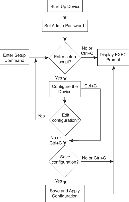
Figure 10-1 Setup Script Flow
You use the setup utility mainly for configuring the system initially, when no configuration is present. However, you can use the setup utility at any time for basic device configuration. The setup utility keeps the configured values when you skip steps in the script. For example, if you have already configured the mgmt0 interface, the setup utility does not change that configuration if you skip that step. However, if there is a default value for the step, the setup utility changes to the configuration using that default, not the configured value. Be sure to carefully check the configuration changes before you save the configuration.
Before starting the setup utility, make sure you perform the following steps:
Step 1. Connect the console port on the supervisor module to the network. If you have dual supervisor modules, connect the console ports on both supervisor modules to the network.
Step 2. Connect the Ethernet management (mgmt) port on the supervisor module to the network. If you have dual supervisor modules, connect the Ethernet management ports on both supervisor modules to the network.
The first time that you access a switch in the Cisco MDS 9000 Family, it runs a setup program that prompts you for the IP address and other configuration information necessary for the switch to communicate over the supervisor module Ethernet interface (mgmt). This information is required to configure and manage the switch. The IP address can only be configured from the CLI. You can configure out-of-band management on the mgmt0 interface.
The in-band management logical interface is VSAN 1. This management interface uses the Fibre Channel infrastructure to transport IP traffic. An interface for VSAN 1 is created on every switch in the fabric. Each switch should have its VSAN 1 interface configured with either an IPv4 address or an IPv6 address in the same subnetwork. A default route that points to the switch providing access to the IP network should be configured on every switch in the Fibre Channel fabric.
Following are the steps to configure out-of-band management on the mgmt0 interface:
Step 1. Power on the switch. Switches in the Cisco MDS 9000 Family boot automatically.
Step 2. Enter yes (yes is the default) to enable the secure password standard.
Do you want to enforce secure password standard (yes/no): yes
You can also enable the secure password standard using the password strength-check command. A secure password should contain characters from at least three of the classes: lowercase letters, uppercase letters, digits, and special characters.
Step 3. Enter the new password for the administrator.
Enter the password for admin: admin-password

Confirm the password for admin: admin-password
If a password is trivial (short, easy-to-decipher), your password configuration is rejected. Be sure to configure a strong password. Passwords are case sensitive.
Step 4. Enter yes to enter the setup mode.
This setup utility will guide you through the basic configuration of the system. Setup configures only enough connectivity for management of the system.

*Note: setup is mainly used for configuring the system initially, when no configuration is present. So setup always assumes system defaults and not the current system configuration values.

Press Enter at anytime to skip a dialog. Use ctrl-c at anytime to skip the remaining dialogs.

Would you like to enter the basic configuration dialog (yes/no): yes
The setup utility guides you through the basic configuration process. Press Ctrl+C at any prompt to end the configuration process.
Step 5. Enter yes (no is the default) if you wish to create additional accounts.
Create another login account (yes/no) [no]: yes
While configuring your initial setup, you can create an additional user account (in the network-admin role) besides the administrator's account.
Enter the user login ID: user_name
Enter the password for user_name: user-password
Confirm the password for user_name: user-password
Enter the user role [network-operator]: network-admin
Step 6. Configure the read-only or read-write SNMP community string.
a. Enter yes (no is the default) to configure the read-only SNMP community string.
Configure read-only SNMP community string (yes/no) [n]: yes
b. Enter the SNMP community string.
SNMP community string: snmp_community
Step 7. Enter a name for the switch. The switch name is limited to 32 alphanumeric characters. The default is switch.
Enter the switch name: switch_name
Step 8. Enter yes (yes is the default) at the configuration prompt to configure out-of-band management.
Continue with Out-of-band (mgmt0) management configuration? [yes/no]: yes
a. Enter the mgmt0 IPv4 address.
Mgmt0 IPv4 address: ip_address
b. Enter the mgmt0 IPv4 subnet mask.
Mgmt0 IPv4 netmask: subnet_mask
Step 9. Enter yes (yes is the default) to configure the default gateway.
Configure the default-gateway: (yes/no) [y]: yes
a. Enter the default gateway IP address.
IP address of the default gateway: default_gateway
Step 10. Enter yes (no is the default) to configure advanced IP options such as in-band management, static routes, default network, DNS, and domain name.
Configure Advanced IP options (yes/no)? [n]: yes
a. Enter no (no is the default) at the in-band management configuration prompt.
Continue with in-band (VSAN1) management configuration? (yes/no) [no]: no
b. Enter yes (yes is the default) to enable IPv4 routing capabilities.
Enable ip routing capabilities? (yes/no) [y]: yes
c. Enter yes (yes is the default) to configure a static route.
Configure static route: (yes/no) [y]: yes
Enter the destination prefix.
Destination prefix: dest_prefix
Enter the destination prefix mask.
Destination prefix mask: dest_mask
Enter the next hop IP address.
Next hop ip address: next_hop_address
d. Enter yes (yes is the default) to configure the default network.
Configure the default-network: (yes/no) [y]: yes
Enter the default network IPv4 address. The default network IPv4 address is the destination prefix provided in step 10c.
Default network IP address [dest_prefix]: dest_prefix
e. Enter yes (yes is the default) to configure the DNS IPv4 address.
Configure the DNS IP address? (yes/no) [y]: yes
Enter the DNS IP address.
DNS IP address: name_server
f. Enter yes (no is the default) to configure the default domain name configuration.
Configure the default domain name? (yes/no) [n]: yes
Enter the default domain name.
Default domain name: domain_name
Step 11. Enter yes (yes is the default) to enable the SSH service.
Enabled SSH service? (yes/no) [n]: yes
Enter the SSH key type.
Type the SSH key you would like to generate (dsa/rsa)? rsa
Enter the number of key bits within the specified range.
Enter the number of key bits? (768-2048) [1024]: 2048
Step 12. Enter yes (no is the default) to configure the Telnet service.
Enable the telnet service? (yes/no) [n]: yes
Step 13. Enter yes (yes is the default) to configure congestion or no_credit drop for FC interfaces.
Configure congestion or no_credit drop for fc interfaces? (yes/no) [q/quit] to quit [y]:yes
Step 14. Enter con or no (con is the default) to configure congestion or no_credit drop.
Enter the type of drop to configure congestion/no_credit drop? (con/no) [c]:con
Step 15. Enter a value from 100 to 1000 (d is the default) to calculate the number of milliseconds for congestion or no_credit drop.
Enter number of milliseconds for congestion/no_credit drop[100 - 1000] or [d/default] for default:100
Step 16. Enter a mode for congestion or no_credit drop.
Enter mode for congestion/no_credit drop[E/F]:
Step 17. Enter yes (no is the default) to configure the NTP server.
Configure NTP server? (yes/no) [n]: yes
Enter the NTP server IPv4 address.
NTP server IP address: ntp_server_IP_address
Step 18. Enter shut (shut is the default) to configure the default switch port interface to the shut (disabled) state.
Configure default switchport interface state (shut/noshut) [shut]: shut
The management Ethernet interface is not shut down at this point. Only the Fibre Channel, iSCSI, FCIP, and Gigabit Ethernet interfaces are shut down.
Step 19. Enter on (off is the default) to configure the switch port trunk mode.
Configure default switchport trunk mode (on/off/auto) [off]: on
Step 20. Enter yes (yes is the default) to configure the switchport mode F.
Configure default switchport mode F (yes/no) [n]: yes
Step 21. Enter on (off is the default) to configure the Port Channel auto-create state.
Configure default port-channel auto-create state (on/off) [off]: on
Step 22. Enter permit (deny is the default) to deny a default zone policy configuration.
Configure default zone policy (permit/deny) [deny]: permit
This configuration permits traffic flow to all members of the default zone.
Step 23. Enter yes (no is the default) to disable a full zone set distribution. This overrides the switch-wide default for the full zone set distribution feature.
Enable full zoneset distribution (yes/no) [n]: yes
You see the new configuration. Review and edit the configuration that you have just entered.
Step 24. Enter enhanced (basic is the default) to configure default-zone mode as enhanced. This overrides the switch-wide default zone mode as enhanced.
Configure default zone mode (basic/enhanced) [basic]: enhanced
Step 25. Enter no (no is the default) if you are satisfied with the configuration.
The following configuration will be applied:
  username admin password admin_pass role network-admin
  username user_name password user_pass role network-admin
  snmp-server community snmp_community ro
  switchname switch
  interface mgmt0
    ip address ip_address subnet_mask
    no shutdown
  ip routing
  ip route dest_prefix dest_mask dest_address
  ip default-network dest_prefix
  ip default-gateway default_gateway
  ip name-server name_server
  ip domain-name domain_name
  telnet server disable
  ssh key rsa 2048 force
  ssh server enable
  ntp server ipaddr ntp_server
  system default switchport shutdown
  system default switchport trunk mode on
  system default switchport mode F
  system default port-channel auto-create
  zone default-zone permit vsan 1-4093
  zoneset distribute full vsan 1-4093
  system default zone mode enhanced
Would you like to edit the configuration? (yes/no) [n]: no
Step 26. Enter yes (yes is default) to use and save this configuration.
Use this configuration and save it? (yes/no) [y]: yes
If you do not save the configuration at this point, none of your changes are updated the next time the switch is rebooted. Type yes to save the new configuration. This ensures that the kickstart and system images are also automatically configured.
Step 27 Log in to the switch using the new username and password and verify that the switch is running the software version that you installed using the previous procedure issuing the show version command.
Example 10-1 displays the show version output.
Example 10-1 Verifying NX-OS Version on an MDS 9100 Switch
switch# show version
Cisco Nexus Operating System (NX-OS) Software
TAC support: http://www.cisco.com/tac
Documents: http://www.cisco.com/en/US/products/ps9372/tsd_products_support_series_home.html
Copyright (c) 2002-2018, Cisco Systems, Inc. All rights reserved.
The copyrights to certain works contained herein are owned by
other third parties and are used and distributed under license.
Some parts of this software are covered under the GNU Public
License. A copy of the license is available at
http://www.gnu.org/licenses/gpl.html.

Software
  BIOS:      version 2.1.17
  loader:    version N/A
  kickstart: version 8.3(1)
  system:    version 8.3(1)
  BIOS compile time:       01/08/14
  kickstart image file is: bootflash:///m9100-s5ek9-kickstart-mz.8.3.1.bin
  kickstart compile time:  7/30/2018 12:00:00 [07/12/2018 04:40:49]
  system image file is:    bootflash:///m9100-s5ek9-mz.8.3.1.bin
  system compile time:     7/30/2018 12:00:00 [07/12/2018 08:32:46]

Hardware
  cisco MDS 9148S 16G 48 FC (1 Slot) Chassis ("2/4/8/16 Gbps FC/Supervisor")
  Motorola, e500v2 with 4088556 kB of memory.
  Processor Board ID JAE1948007Z

  Device name: MDS-2
  bootflash:    4001760 kB

Kernel uptime is 5 day(s), 21 hour(s), 28 minute(s), 7 second(s)

Last reset at 312523 usecs after Thu Aug 22 04:58:00 2019
  Reason: Reset Requested by CLI command reload
  System version: 8.3(1)
  Service:
plugin
  Core Plugin
switch#
You can configure both in-band and out-of-band configuration together by entering yes in steps 10a, 10c, and 10d in the previous procedure, as shown in the following excerpt.
The following is the initial setup procedure for configuring the in-band management logical interface on VSAN 1:
Step 10. Enter yes (no is the default) to configure advanced IP options such as in-band management, static routes, default network, DNS, and domain name.
Configure Advanced IP options (yes/no)? [n]: yes
a. Enter yes (no is the default) at the in-band management configuration prompt.
Continue with in-band (VSAN1) management configuration? (yes/no) [no]: yes
Enter the VSAN 1 IPv4 address.
VSAN1 IPv4 address: ip_address
Enter the IPv4 subnet mask.
VSAN1 IPv4 net mask: subnet_mask
b. Enter no (yes is the default) to enable IPv4 routing capabilities.
Enable ip routing capabilities? (yes/no) [y]: no
c. Enter no (yes is the default) to configure a static route.
Configure static route: (yes/no) [y]: no
d. Enter no (yes is the default) to configure the default network
Configure the default-network: (yes/no) [y]: no
e. Enter no (yes is the default) to configure the DNS IPv4 address.
Configure the DNS IP address? (yes/no) [y]: no
f. Enter no (no is the default) to skip the default domain name configuration.
Configure the default domain name? (yes/no) [n]: no
Note
If you are executing the setup script after issuing a write erase command, you must explicitly change the default zoning mode to enhanced for VSAN 1 after finishing the script by using the following commands:
switch# configure terminal
switch(config)# zone mode enhanced vsan 1
Cisco MDS NX-OS Software Upgrade and Downgrade
A Cisco MDS switch is shipped with the Cisco MDS NX-OS operating system for the Cisco MDS 9000 Series multilayer directors and fabric switches. The Cisco MDS NX-OS software consists of two images: the kickstart image and the system image.
The software image install procedure depends on the following factors:
• Software images: The kickstart and system image files reside in directories or folders that can be accessed from the Cisco MDS 9000 Series multilayer switch prompt.
• Image version: Each image file has a version.
• Flash disks on the switch: The bootflash: resides on the supervisor module, and the CompactFlash disk is inserted into the slot0: device.
• Supervisor modules: Either single or dual supervisor modules are present. To realize the benefits of a nondisruptive upgrade on the Cisco MDS 9700 Series multilayer directors, you should install dual supervisor modules per the Cisco recommendation.
To determine the version of the Cisco MDS NX-OS software that is currently running on a Cisco MDS 9000 switch using the CLI, log in to the switch and run the show version command in privileged EXEC mode.
Use the show incompatibility-all system bootflash: system image filename command to determine which features are incompatible with the destination upgrade release, as follows:
switch(config)# show incompatibility-all system bootflash:m9700-sf4ek9-mz.8.4.1.bin

Checking incompatible configuration(s):
No incompatible configurations

Checking dynamic incompatibilities:
No incompatible configurations
No payload encryption (NPE) images are also available with the Cisco MDS NX-OS software. The NPE images are intended for countries that have import restrictions on products that encrypt payload data. To differentiate an NPE image from a standard software image, the letters NPE are included in the image. Nondisruptive software upgrades or downgrades between NPE images and non-NPE images are not supported.
You can upgrade any switch in the Cisco MDS 9000 Family using one of the following methods:
• Automated, one-step upgrade using the install all command: This upgrade is nondisruptive. The install all command upgrades all modules in any Cisco MDS 9000 Family switch. Cisco recommends having dual supervisors installed on the MDS switch while performing a nondisruptive upgrade. Although a nondisruptive update doesn’t require a switch reload, it disrupts the control plane for about 80 seconds.
• Quick, one-step upgrade using the reload command: This upgrade is disruptive and requires a switch reload. Before running the reload command, copy the correct kickstart and system images to the correct location in bootflash and change the boot commands in your configuration.
Note
An upgrade or downgrade of control plane software that results in the data plane going down for any period of time is called a disruptive (or hitful) upgrade or downgrade, respectively. This includes a stateless restart. An upgrade or downgrade of control plane software that does not take down the data plane for any period of time is called a nondisruptive (or hitless) upgrade or downgrade, respectively. This includes a stateful restart.
When the Cisco MDS Series switch is first switched on or during reboot, the switch follows the boot sequence shown in Figure 10-2.
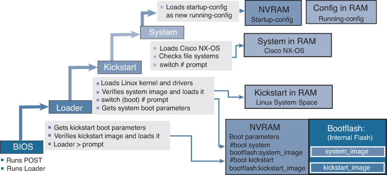
Figure 10-2 Boot Sequence
The BIOS on the supervisor module first runs power-on self-test (POST) diagnostics and then runs the loader bootstrap function. The boot parameters are held in NVRAM and point to the location and name of both the kickstart and system images. The loader obtains the location of the kickstart file, usually on bootflash, and verifies the kickstart image before loading it.
The kickstart loads the Linux kernel and device drivers and then needs to load the system image. Again, the boot parameters in NVRAM should point to the location and name of the system image, usually on bootflash. The kickstart then verifies the system image and loads it.
Finally, the system image loads the Cisco NX-OS software, checks the file systems, and proceeds to load the startup configuration, containing the switch configuration, from NVRAM.
If the boot parameters are missing or have an incorrect name or location, the boot process fails at the last stage. If this happens, the administrator must recover from the error and reload the switch. The install all command is a script that greatly simplifies the boot procedure and checks for errors and the upgrade impact before proceeding.
We discuss the disruptive and nondisruptive upgrade and downgrade procedures in detail in the following sections.
Nondisruptive Upgrade on a Cisco MDS Fabric Switch
Let’s first look at the process for a nondisruptive upgrade on a Cisco MDS fabric switch.
![]()
Before performing an upgrade, use the show install all impact command to view the effect of updating the system from the running image to another specified image.
Step 1. Verify that the system image files for the upgrade are present on the active supervisor module bootflash:
switch# dir bootflash:

25863680 Sep 23 12:02:16 2017 m9250-s5ek9-kickstart-mz.8.2.1.bin
25864704 Sep 05 12:21:26 2018 m9250-s5ek9-kickstart-mz.8.2.1.bin
25869312 Apr 01 12:29:34 2018 m9250-s5ek9-kickstart-mz.8.2.2.bin
25869312 Apr 12 01:55:22 2018 m9250-s5ek9-kickstart-mz.8.2.2.bin
25947136 Nov 09 13:41:43 2018 m9250-s5ek9-kickstart-mz.8.3.1.bin
25970176 Jan 17 14:10:47 2019 m9250-s5ek9-kickstart-mz.8.3.2.bin
26126848 May 07 11:51:20 2019 m9250-s5ek9-kickstart-mz.8.4.1.bin

Usage for bootflash://sup-local

2838728704 bytes used
520916992 bytes free
3359645696 bytes total
Step 2. If the software image file is not present, download it from an FTP or TFTP server to bootflash. You can obtain the software image file from the Cisco.com Software Download Center at http://www.cisco.com/cisco/software/navigator.html.
switch# copy tftp://tftpserver.cisco.com/MDS/m9250-s5ek9-kickstart-mz.8.4.1.bin bootflash:m9250-s5ek9-kickstart-mz.8.4.1.bin
switch# copy tftp://tftpserver.cisco.com/MDS/m9250-s5ek9-mz.8.4.1.bin bootflash:m9250-s5ek9-mz.8.4.1.bin
Step 3. Ensure that the required space is available on the switch:
switch# dir bootflash:
25863680 Sep 23 12:02:16 2017 m9250-s5ek9-kickstart-mz.8.2.1.bin
25864704 Sep 05 12:21:26 2018 m9250-s5ek9-kickstart-mz.8.2.1.bin
25869312 Apr 01 12:29:34 2018 m9250-s5ek9-kickstart-mz.8.2.2.bin
25869312 Apr 12 01:55:22 2018 m9250-s5ek9-kickstart-mz.8.2.2.bin
25947136 Nov 09 13:41:43 2018 m9250-s5ek9-kickstart-mz.8.3.1.bin
25970176 Jan 17 14:10:47 2019 m9250-s5ek9-kickstart-mz.8.3.2.bin
26126848 May 07 11:51:20 2019 m9250-s5ek9-kickstart-mz.8.4.1.bin

Usage for bootflash://sup-local
120695976 bytes used
63863640 bytes free
184559616 bytes total
Step 4. If you need more space on the switch, delete the files that are not required:
switch# delete bootflash: m9250-s5ek9-kickstart-mz.8.2.1.bin
switch# delete bootflash: m9250-s5ek9-kickstart-mz.8.2.1.bin
Step 5. Save the configuration using the copy running-config startup-config command:
switch# copy running-config startup-config
You can also back up your existing configuration to a file, using the copy running-config bootflash:backup_config.txt command. You can add a date reference to the .txt filename to identify the file later.
Step 6. Perform the upgrade by running the install all command:
switch# install all kickstart m9250-s5ek9-kickstart-mz.8.4.1.bin system m9250-s5ek9-mz.8.4.1.bin
Installer will perform compatibility check first. Please wait.
y
Verifying image bootflash:/m9250-s5ek9-kickstart-mz.8.4.1.bin for boot variable "kickstart".
[# ] 0%
[####################] 100% -- SUCCESS
Verifying image bootflash:/m9250-s5ek9-mz.8.4.1.bin for boot variable "system".
[####################] 100% -- SUCCESS
Performing module support checks.
[####################] 100% -- SUCCESS
Verifying image type.
[####################] 100% -- SUCCESS
Extracting "system" version from image bootflash:/m9250-s5ek9-mz.8.4.1.bin
[####################] 100% -- SUCCESS
Extracting "kickstart" version from image bootflash:/m9250-s5ek9-kickstart-mz.8.4.1.bin
[####################] 100% -- SUCCESS
Extracting "bios" version from image bootflash:/m9250-s5ek9-mz.8.4.1.bin
[####################] 100% -- SUCCESS
Performing Compact Flash and TCAM sanity test.
[####################] 100% -- SUCCESS
Notifying services about system upgrade.
[####################] 100% -- SUCCESS
Compatibility check is done:
Module bootable Impact Install-type   Reason
------ -------- ------ -------------- ------
1               yes    non-disruptive reset

Other miscellaneous information for installation:
Module info
------ ----------------------------------
1      FC ports 1-40 and FCoE ports 1-8 are hitless, IPS 1-2 are hitful, and Intelligent Applications running are hitful

Images will be upgraded according to following table:
Module Image     Running-Version                     New-Version      Upg-Required
------ --------- ----------------------------------- ---------------  ------------
1      system    8.1(1)                              8.4(1)            yes
1      kickstart 8.1(1)                              8.4(1)            yes
1      bios      v2.1.17(01/08/14):v2.1.17(01/08/14) v2.1.17(01/08/14) no

Do you want to continue with the installation (y/n)? [n] y
Install is in progress, please wait.
Performing runtime checks.
[####################] 100% -- SUCCESS
Notifying services about the upgrade.
[####################] 100% -- SUCCESS
Setting boot variables.
[####################] 100% -- SUCCESS
Performing configuration copy.
[####################] 100% -- SUCCESS
Module 1: Refreshing compact flash and Upgrading bios/loader/bootrom/power-seq.
Warning: please do not remove or power off the module at this time.
[####################] 100% -- SUCCESS
Upgrade can no longer be aborted, any failure will result in a disruptive upgrade.
Freeing memory in the file system.
[####################] 100% -- SUCCESS
Loading images into memory.
[####################] 100% -- SUCCESS
Saving linecard runtime state.
[####################] 100% -- SUCCESS
Saving supervisor runtime state.
[####################] 100% -- SUCCESS
Saving mts state.
[####################] 100% -- SUCCESS
Reloading the kernel to proceed with the upgrade.
<output omitted>
Loading system software
Uncompressing system image: bootflash:///m9250-s5ek9-mz.8.4.1.bin
CCCCCCCCCCCCCCCCCCCCCCCCCCCCCCCCCCCCCCCCCCCCCCCCCCCCCCCCCCCCCCCCCCCC
Load plugins that defined in image conf: /isan/plugin_img/img.conf
<output omitted>Continuing with installation process, please wait.
The login will be disabled until the installation is completed.
Status for linecard upgrade.
[####################] 100% -- SUCCESS
Performing supervisor state verification.
[####################] 100% -- SUCCESS
Supervisor non-disruptive upgrade successful.
Install has been successful.
Step 7. Log in to the switch:
MDS Switch
x.x.x.x login: admin
Cisco Nexus Operating System (NX-OS) Software
TAC support: http://www.cisco.com/tac
Copyright (c) 2002-2014, Cisco Systems, Inc. All rights reserved.
The copyrights to certain works contained in this software are
owned by other third parties and used and distributed under
license. Certain components of this software are licensed under
the GNU General Public License (GPL) version 2.0 or the GNU
Lesser General Public License (LGPL) Version 2.1. A copy of each
such license is available at
http://www.opensource.org/licenses/gpl-2.0.php and
http://www.opensource.org/licenses/lgpl-2.1.php
Step 8. Run the show version command to verify the upgraded image version:
switch# show version
Cisco Nexus Operating System (NX-OS) Software
TAC support: http://www.cisco.com/tac
Documents: http://www.cisco.com/en/US/products/ps9372/tsd_products_support_series_home.html
Copyright (c) 2002-2019, Cisco Systems, Inc. All rights reserved.
The copyrights to certain works contained herein are owned by
other third parties and are used and distributed under license.
Some parts of this software are covered under the GNU Public
License. A copy of the license is available at
http://www.gnu.org/licenses/gpl.html.
Software
BIOS: version 2.1.17
loader: version N/A
kickstart: version 8.4(1) [build 8.4(1)]
system: version 8.4(1) [build 8.4(1)]
BIOS compile time: 01/08/14
kickstart image file is: bootflash:///m9250-s5ek9-kickstart-mz.8.4.1.bin
kickstart compile time: 6/1/2019 23:00:00 [05/07/2019 04:18:10]
system image file is: bootflash:///m9250-s5ek9-mz.8.4.1.bin
system compile time: 6/1/2019 23:00:00 [05/07/2019 07:09:57]
Hardware
cisco MDS 9250i 40 FC 2 IPS 8 FCoE (2 RU) Chassis ("40FC+8FCoE+2IPS Supervisor")
Motorola, e500v2 with 4088636 kB of memory.
Processor Board ID JAF1804AAFG
Device name: MDS9250i
bootflash: 4001760 kB
Kernel uptime is 0 day(s), 0 hour(s), 7 minute(s), 42 second(s)
Last reset at 288238 usecs after Thu May 9 11:40:56 2019
Reason: Reset due to upgrade
System version: 8.1(1)
Service:
plugin
Core Plugin
Step 9. Verify the status of the modules on the switch, using the show module command:
switch# show module

Mod Ports Module-Type                Model             Status
--- ----- -------------------------- ----------------- ----------
1    50   40FC+8FCoE+2IPS Supervisor DS-C9250I-K9-SUP  active *
Mod Sw     Hw   World-Wide-Name(s) (WWN)
--- ------ ---- ---------------------------------------------------
1   8.4(1) 1.0  20:01:00:2a:6a:1b:64:d0 to 20:28:00:2a:6a:1b:64:d0
Mod MAC-Address(es)                        Serial-Num
--- -------------------------------------- ----------
1   b8-38-61-4a-25-c0 to b8-38-61-4a-25-cf JAF1804AAFG
Step 10. To display the status of a nondisruptive upgrade on a fabric switch, use the show install all status command. The command output displays the status only after the switch has rebooted with the new image. All the actions preceding the reboot are not captured in this output because when you enter the install all command using a Telnet session, the session is disconnected when the switch reboots. When you reconnect to the switch through a Telnet session, the upgrade may already be complete, in which case, the output displays the status of the upgrade.
switch# show install all status

This is the log of last installation.

Continuing with installation process, please wait.
The login will be disabled until the installation is completed.

Status for linecard upgrade.
-- SUCCESS

Performing supervisor state verification.
-- SUCCESS

Install has been successful
Disruptive Upgrade on a Cisco MDS Fabric Switch
![]()
Now let’s look at the process for a disruptive upgrade on a Cisco MDS fabric switch.
Step 1. Verify that the system image files for the upgrade are present on the active supervisor module bootflash:
switch# dir bootflash:

25863680 Sep 23 12:02:16 2017 m9250-s5ek9-kickstart-mz.8.2.1.bin
25864704 Sep 05 12:21:26 2018 m9250-s5ek9-kickstart-mz.8.2.1.bin
25869312 Apr 01 12:29:34 2018 m9250-s5ek9-kickstart-mz.8.2.2.bin
25869312 Apr 12 01:55:22 2018 m9250-s5ek9-kickstart-mz.8.2.2.bin
25947136 Nov 09 13:41:43 2018 m9250-s5ek9-kickstart-mz.8.3.1.bin
25970176 Jan 17 14:10:47 2019 m9250-s5ek9-kickstart-mz.8.3.2.bin
26126848 May 07 11:51:20 2019 m9250-s5ek9-kickstart-mz.8.4.1.bin

Usage for bootflash://sup-local

2838728704 bytes used
520916992 bytes free
3359645696 bytes total
Step 2. If the software image file is not present, download it from an FTP or TFTP server to bootflash. You can obtain the software image file from the Cisco.com Software Download Center at http://www.cisco.com/cisco/software/navigator.html.
switch# copy tftp://tftpserver.cisco.com/MDS/m9250-s5ek9-kickstart-mz.8.4.1.bin bootflash:m9250-s5ek9-kickstart-mz.8.4.1.bin
switch# copy tftp://tftpserver.cisco.com/MDS/m9250-s5ek9-mz.8.4.1.bin bootflash:m9250-s5ek9-mz.8.4.1.bin
Step 3. Ensure that the required space is available on the switch:
switch# dir bootflash:
25863680 Sep 23 12:02:16 2017 m9250-s5ek9-kickstart-mz.8.2.1.bin
25864704 Sep 05 12:21:26 2018 m9250-s5ek9-kickstart-mz.8.2.1.bin
25869312 Apr 01 12:29:34 2018 m9250-s5ek9-kickstart-mz.8.2.2.bin
25869312 Apr 12 01:55:22 2018 m9250-s5ek9-kickstart-mz.8.2.2.bin
25947136 Nov 09 13:41:43 2018 m9250-s5ek9-kickstart-mz.8.3.1.bin
25970176 Jan 17 14:10:47 2019 m9250-s5ek9-kickstart-mz.8.3.2.bin
26126848 May 07 11:51:20 2019 m9250-s5ek9-kickstart-mz.8.4.1.bin

Usage for bootflash://sup-local
120695976 bytes used
63863640 bytes free
184559616 bytes total
Step 4. If you need more space on the switch, delete the files that are not required:
switch# delete bootflash: m9250-s5ek9-kickstart-mz.8.2.1.bin
switch# delete bootflash: m9250-s5ek9-kickstart-mz.8.2.1.bin
Step 5. Change the boot statements on the switch to reflect the new system software.
switch# configure terminal
switch(config)# no boot kickstart bootflash:/m9250-s5ek9-kickstart-mz.8.2.1.bin
switch(config)# no boot system bootflash:/m9250-s5ek9-mz.8.2.1.bin
switch(config)# boot kickstart bootflash:/m9250-s5ek9-kickstart-mz.8.4.1.bin
switch(config)# boot system bootflash:/m9250-s5ek9-mz.8.4.1.bin
switch(config)# exit
Step 6. Save the configuration using the copy running-config startup-config command:
switch# copy running-config startup-config
You can also back up your existing configuration to a file by using the copy running-config bootflash:backup_config.txt command. You can add a date reference to the .txt filename to identify the file later.
Step 7. Reload the switch using the reload command:
switch# reload
!!!WARNING! there is unsaved configuration!!!
This command will reboot the system. (y/n)?  [n] y
Step 8. Log in to the switch:
MDS Switch
x.x.x.x login: admin
Cisco Nexus Operating System (NX-OS) Software
TAC support: http://www.cisco.com/tac
Copyright (c) 2002-2014, Cisco Systems, Inc. All rights reserved.
The copyrights to certain works contained in this software are
owned by other third parties and used and distributed under
license. Certain components of this software are licensed under
the GNU General Public License (GPL) version 2.0 or the GNU
Lesser General Public License (LGPL) Version 2.1. A copy of each
such license is available at
http://www.opensource.org/licenses/gpl-2.0.php and
http://www.opensource.org/licenses/lgpl-2.1.php
Step 9. Run the show version command to verify the new image on the switch:
switch# show version
Cisco Nexus Operating System (NX-OS) Software
TAC support: http://www.cisco.com/tac
Documents: http://www.cisco.com/en/US/products/ps9372/tsd_products_support_series_home.html
Copyright (c) 2002-2019, Cisco Systems, Inc. All rights reserved.
The copyrights to certain works contained herein are owned by
other third parties and are used and distributed under license.
Some parts of this software are covered under the GNU Public
License. A copy of the license is available at
http://www.gnu.org/licenses/gpl.html.
Software
BIOS: version 2.1.17
loader: version N/A
kickstart: version 8.4(1) [build 8.4(1)]
system: version 8.4(1) [build 8.4(1)]
BIOS compile time: 01/08/14
kickstart image file is: bootflash:///m9250-s5ek9-kickstart-mz.8.4.1.bin
kickstart compile time: 6/1/2019 23:00:00 [05/07/2019 04:18:10]
system image file is: bootflash:///m9250-s5ek9-mz.8.4.1.bin
system compile time: 6/1/2019 23:00:00 [05/07/2019 07:09:57]
Hardware
cisco MDS 9250i 40 FC 2 IPS 8 FCoE (2 RU) Chassis ("40FC+8FCoE+2IPS Supervisor")
Motorola, e500v2 with 4088636 kB of memory.
Processor Board ID JAF1804AAFG
Device name: MDS9250i
bootflash: 4001760 kB
Kernel uptime is 0 day(s), 0 hour(s), 7 minute(s), 42 second(s)
Last reset at 288238 usecs after Thu May 9 11:40:56 2019
Reason: Reset due to upgrade
System version: 8.1(1)
Service:
plugin
Core Plugin
Step 10. Verify the status of the modules on the switch, using the show module command:
switch# show module

Mod Ports Module-Type                Model             Status
--- ----- -------------------------- ----------------- ----------
1    50   40FC+8FCoE+2IPS Supervisor DS-C9250I-K9-SUP  active *
Mod Sw     Hw   World-Wide-Name(s) (WWN)
--- ------ ---- ---------------------------------------------------
1   8.4(1) 1.0  20:01:00:2a:6a:1b:64:d0 to 20:28:00:2a:6a:1b:64:d0
Mod MAC-Address(es)                        Serial-Num
--- -------------------------------------- ----------
1   b8-38-61-4a-25-c0 to b8-38-61-4a-25-cf JAF1804AAFG
Nondisruptive Downgrade on a Cisco MDS Fabric Switch
![]()
Next, let’s look at the process for a nondisruptive downgrade on a Cisco MDS fabric switch.
Step 1. Verify that the system image files for the downgrade are present in the active supervisor module bootflash:
switch# dir bootflash:

26126848 May 07 11:51:20 2019 m9250-s5ek9-kickstart-mz.8.4.1.bin
20090368 Apr 06 05:25:31 2001 m9250-s5ek9-kickstart-mz.7.3.1.DY.1.bin
20044800 Mar 30 15:42:05 2014 m9250-s5ek9-kickstart-mz.6.2.7.bin
107197681 Apr 06 05:26:53 2001 m9250-s5ek9-mz.6.2.5.bin.S68
107587249 Mar 30 15:42:52 2014 m9250-s5ek9-mz.6.2.7.bin
Step 2. If the software image file is not present, download it from an FTP or TFTP server to the active supervisor module bootflash. You can obtain the software image file from the Cisco.com Software Download Center: http://www.cisco.com/cisco/software/navigator.html.
switch# copy tftp://tftpserver.cisco.com/MDS/m9250-s5ek9-kickstart-mz.7.3.1.DY.1.bin bootflash:m9250-s5ek9-kickstart-mz.7.3.1.DY.1.bin
switch# copy tftp://tftpserver.cisco.com/MDS/m9250-s5ek9-kickstart-mz.7.3.1.DY.1.bin bootflash:m9250-s5ek9-kickstart-mz.7.3.1.DY.1.bin
Step 3. Ensure that the required space is available in the active supervisor:
switch# dir bootflash:

26126848 May 07 11:51:20 2019 m9250-s5ek9-kickstart-mz.8.4.1.bin
12288 Aug 26 19:06:14 2011 lost+found/
18939904 Jul 01 10:54:49 2011 m9250-s5ek9-kickstart-mz.6.2.5.bin
101756072 Jul 01 10:33:52 2011 m9250-s5ek9-mz.6.2.5.bin

Usage for bootflash://sup-local
120695976 bytes used
63863640 bytes free
184559616 bytes total
Step 4. If you need more space in the active supervisor module bootflash, delete the files that are not required, to make space available:
switch# delete bootflash: m9250-s5ek9-kickstart-mz.6.2.5.bin
switch# delete bootflash: m9250-s5ek9-kickstart-mz.6.2.5.bin
Step 5. Run the show incompatibility system image-filename command to determine whether you must disable the features not supported by a release earlier than the release that is installed.
switch# show incompatibility system bootflash:m9250-s5ek9-kickstart-mz.7.3.1.DY.1.bin
no incompatible configuration
Step 6. Save the configuration using the copy running-config startup-config command:
switch# copy running-config startup-config
Step 7. Run the install all command to downgrade the software:
switch(config)# install all kickstart m9250-s5ek9-kickstart-mz.7.3.1.DY.1.bin system m9250-s5ek9-mz.7.3.1.DY.1.bin
Installer will perform compatibility check first. Please wait.

Verifying image bootflash:/m9250-s5ek9-kickstart-mz.7.3.1.DY.1.bin for boot variable "kickstart".
[####################] 100% -- SUCCESS

Verifying image bootflash:/m9250-s5ek9-mz.7.3.1.DY.1.bin for boot variable "system".
[####################] 100% -- SUCCESS

Performing module support checks.
[####################] 100% -- SUCCESS

Verifying image type.
[####################] 100% -- SUCCESS

Extracting "system" version from image bootflash:/m9250-s5ek9-mz.7.3.1.DY.1.bin.
[####################] 100% -- SUCCESS

Extracting "kickstart" version from image bootflash:/m9250-s5ek9-kickstart-mz.7.3.1.DY.1.bin.
[####################] 100% -- SUCCESS

Extracting "bios" version from image bootflash:/m9250-s5ek9-mz.7.3.1.DY.1.bin.
[####################] 100% -- SUCCESS

Performing Compact Flash and TCAM sanity test.
[####################] 100% -- SUCCESS

Notifying services about system upgrade.
[####################] 100% -- SUCCESS


Compatibility check is done:

Module bootable Impact Install-type   Reason
------ -------- ------ -------------- ------
1               yes    non-disruptive reset

Other miscellaneous information for installation:

Module info
------ ----------------------------------
1      FC ports 1-40 and FCoE ports 1-8 are hitless, IPS 1-2 are hitful, and Intelligent Applications running are hitful

Images will be upgraded according to following table:
Module    Image      Running-Version                  New-Version         Upg-Required
------  ----------  -----------------------------------  ------------------  ------------
 1       system     8.1(1b)                              7.3(1)DY(1)           yes
 1       kickstart  8.1(1b)                              7.3(1)DY(1)           yes
 1       bios       v2.1.17(01/08/14):v2.1.17(01/08/14)  v2.1.17(01/08/14)     no

Do you want to continue with the installation (y/n)?  [n] y

Install is in progress, please wait.

Performing runtime checks.
[####################] 100% -- SUCCESS

Notifying services about the upgrade.
[####################] 100% -- SUCCESS

Setting boot variables.
[####################] 100% -- SUCCESS

Performing configuration copy.
[####################] 100% -- SUCCESS

Module 1: Refreshing compact flash and Upgrading bios/loader/bootrom/power-seq.
Warning: please do not remove or power off the module at this time.
[####################] 100% -- SUCCESS

Converting startup config.
[####################] 100% -- SUCCESS

Upgrade can no longer be aborted, any failure will result in a disruptive upgrade.

Freeing memory in the file system.
[####################] 100% -- SUCCESS

Loading images into memory.
[####################] 100% -- SUCCESS

Saving linecard runtime state.
[####################] 100% -- SUCCESS

Saving supervisor runtime state.
[####################] 100% -- SUCCESS

Saving mts state.
[####################] 100% -- SUCCESS

Reloading the kernel to proceed with the upgrade.
All telnet and ssh connections will now be temporarily terminated.
<output omitted>

Status for linecard upgrade.
[####################] 100% -- SUCCESS

Performing supervisor state verification.
[####################] 100% -- SUCCESS

Install has been successful.
Step 8. Run the show version command to verify the successful downgrade:
switch# show version

Cisco Nexus Operating System (NX-OS) Software
TAC support: http://www.cisco.com/tac
Documents: http://www.cisco.com/en/US/products/ps9372/tsd_products_support_series_home.html
Copyright (c) 2002-2016, Cisco Systems, Inc. All rights reserved.
The copyrights to certain works contained herein are owned by
other third parties and are used and distributed under license.
Some parts of this software are covered under the GNU Public
License. A copy of the license is available at
http://www.gnu.org/licenses/gpl.html.

Software
BIOS: version 2.1.17
loader: version N/A
kickstart: version 7.3(1)DY(1)
system: version 7.3(1)DY(1)
BIOS compile time: 01/08/14
kickstart image file is: bootflash:///m9250-s5ek9-kickstart-mz.7.3.1.DY.1.bin.S21
kickstart compile time: 1/11/2016 16:00:00 [02/11/2016 10:35:42]
system image file is: bootflash:///m9250-s5ek9-mz.7.3.1.DY.1.bin.S21
system compile time: 1/11/2016 16:00:00 [02/11/2016 13:08:53]

Hardware
cisco MDS 9250i 40 FC 2 IPS 8 FCoE (2 RU) Chassis ("40FC+8FCoE+2IPS Supervisor")
Motorola, e500v2, core 0 with 4155752 kB of memory.
Processor Board ID JAF1626BCQH

Device name: alishan-dr
bootflash: 4013856 kB

Kernel uptime is 0 day(s), 17 hour(s), 18 minute(s), 58 second(s)

Last reset at 443194 usecs after Wed Aug 31 10:58:41 2016

Reason: Reset due to upgrade
System version: 7.3(1)DY(1)
Service:

plugin
Core Plugin
switch#
Step 9. Verify the status of the modules in the switch, using the show module command:
switch# show module

Mod Ports Module-Type                 Model               Status
--- ----- --------------------------  ------------------- -------
1   50    40FC+8FCoE+2IPS Supervisor  DS-C9250i-22PK9-SUP active *

Mod Sw          Hw   World-Wide-Name(s) (WWN)
--- ----------- ---- --------------------------------------------------
1   7.3(1)DY(1) 0.9  20:01:54:7f:ee:1b:14:a0 to 20:28:54:7f:ee:1b:14:a0

Mod MAC-Address(es)                        Serial-Num
--- -------------------------------------- ----------
1   f0-f7-55-29-50-60 to f0-f7-55-29-50-6f JAF1626BCQH

* this terminal session

switch#
Disruptive Downgrade on a Cisco MDS Switch
![]()
Finally, let’s look at the process for a disruptive downgrade on a Cisco MDS fabric switch.
Step 1. Verify that the system image files for the downgrade are present in the active supervisor module bootflash:
switch# dir bootflash:

26126848 May 07 11:51:20 2019 m9250-s5ek9-kickstart-mz.8.4.1.bin
20090368 Apr 06 05:25:31 2001 m9250-s5ek9-kickstart-mz.7.3.1.DY.1.bin
20044800 Mar 30 15:42:05 2014 m9250-s5ek9-kickstart-mz.6.2.7.bin
107197681 Apr 06 05:26:53 2001 m9250-s5ek9-mz.6.2.5.bin.S68
107587249 Mar 30 15:42:52 2014 m9250-s5ek9-mz.6.2.7.bin
Step 2. If the software image file is not present, download it from an FTP or TFTP server to the active supervisor module bootflash. You can obtain the software image file from the Cisco.com Software Download Center: http://www.cisco.com/cisco/software/navigator.html.
switch# copy tftp://tftpserver.cisco.com/MDS/m9250-s5ek9-kickstart-mz.7.3.1.DY.1.bin bootflash:m9250-s5ek9-kickstart-mz.7.3.1.DY.1.bin
switch# copy tftp://tftpserver.cisco.com/MDS/m9250-s5ek9-kickstart-mz.7.3.1.DY.1.bin bootflash:m9250-s5ek9-kickstart-mz.7.3.1.DY.1.bin
Step 3. Ensure that the required space is available in the active supervisor:
switch# dir bootflash:

26126848 May 07 11:51:20 2019 m9250-s5ek9-kickstart-mz.8.4.1.bin
12288 Aug 26 19:06:14 2011 lost+found/
18939904 Jul 01 10:54:49 2011 m9250-s5ek9-kickstart-mz.6.2.5.bin
101756072 Jul 01 10:33:52 2011 m9250-s5ek9-mz.6.2.5.bin

Usage for bootflash://sup-local
120695976 bytes used
63863640 bytes free
184559616 bytes total
Step 4. If you need more space in the active supervisor module bootflash, delete the files that are not required, to make space available:
switch# delete bootflash: m9250-s5ek9-kickstart-mz.6.2.5.bin
switch# delete bootflash: m9250-s5ek9-kickstart-mz.6.2.5.bin
Step 5. Run the show incompatibility system image-filename command to determine whether you must disable the features not supported by a release earlier than the release that is installed:
switch# show incompatibility system bootflash:m9250-s5ek9-kickstart-mz.7.3.1.DY.1.bin
no incompatible configuration
Step 6. Change the boot statements on the switch to reflect the new system software:
switch# configure terminal
switch(config)# no boot kickstart bootflash:/m9250-s5ek9-kickstart-mz.8.2.1.bin
switch(config)# no boot system bootflash:/m9250-s5ek9-mz.8.2.1.bin
switch(config)# boot kickstart bootflash:/m9250-s5ek9-kickstart-mz.7.3.1.DY.1.bin
switch(config)# boot system bootflash:/m9250-s5ek9-kickstart-mz.7.3.1.DY.1.bin
switch(config)# exit
Step 7. Save the configuration using the copy running-config startup-config command:
switch# copy running-config startup-config
You can also back up your existing configuration to a file, using the copy running-config bootflash:backup_config.txt command. You can add a date reference to the .txt filename to identify the file later.
Step 8. Reload the switch using the reload command:
switch# reload
!!!WARNING! there is unsaved configuration!!!
This command will reboot the system. (y/n)?  [n] y
Step 9. Run the show version command to verify the successful downgrade:
switch# show version

Cisco Nexus Operating System (NX-OS) Software
TAC support: http://www.cisco.com/tac
Documents: http://www.cisco.com/en/US/products/ps9372/tsd_products_support_series_home.html
Copyright (c) 2002-2016, Cisco Systems, Inc. All rights reserved.
The copyrights to certain works contained herein are owned by
other third parties and are used and distributed under license.
Some parts of this software are covered under the GNU Public
License. A copy of the license is available at
http://www.gnu.org/licenses/gpl.html.

Software
BIOS: version 2.1.17
loader: version N/A
kickstart: version 7.3(1)DY(1)
system: version 7.3(1)DY(1)
BIOS compile time: 01/08/14
kickstart image file is: bootflash:///m9250-s5ek9-kickstart-mz.7.3.1.DY.1.bin.S21
kickstart compile time: 1/11/2016 16:00:00 [02/11/2016 10:35:42]
system image file is: bootflash:///m9250-s5ek9-mz.7.3.1.DY.1.bin.S21
system compile time: 1/11/2016 16:00:00 [02/11/2016 13:08:53]

Hardware
cisco MDS 9250i 40 FC 2 IPS 8 FCoE (2 RU) Chassis ("40FC+8FCoE+2IPS Supervisor")
Motorola, e500v2, core 0 with 4155752 kB of memory.
Processor Board ID JAF1626BCQH

Device name: alishan-dr
bootflash: 4013856 kB

Kernel uptime is 0 day(s), 17 hour(s), 18 minute(s), 58 second(s)

Last reset at 443194 usecs after Wed Aug 31 10:58:41 2016

Reason: Reset due to upgrade
System version: 7.3(1)DY(1)
Service:

plugin
Core Plugin
switch#
Step 10. Verify the status of the modules in the switch, using the show module command:
switch# show module

Mod Ports Module-Type                 Model               Status
--- ----- --------------------------  ------------------- -------
1   50    40FC+8FCoE+2IPS Supervisor  DS-C9250i-22PK9-SUP active *

Mod Sw          Hw   World-Wide-Name(s) (WWN)
--- ----------- ---- --------------------------------------------------
1   7.3(1)DY(1) 0.9  20:01:54:7f:ee:1b:14:a0 to 20:28:54:7f:ee:1b:14:a0

Mod MAC-Address(es)                        Serial-Num
--- -------------------------------------- ----------
1   f0-f7-55-29-50-60 to f0-f7-55-29-50-6f JAF1626BCQH

* this terminal session

switch#
EPLD Upgrade on Cisco MDS 9000 Series Switches
Switches and directors in the Cisco MDS 9000 Series contain several electrical programmable logical devices (EPLDs) that provide hardware functionalities in all of the modules. Cisco periodically provides EPLD image upgrades to include enhanced hardware functionality or to resolve known issues.
EPLD images are released as part of a Cisco MDS NX-OS release. Therefore, the EPLD images have a version number that matches the Cisco MDS NX-OS release they are part of.
An EPLD image is a package containing updates for each type of EPLD. Because EPLD changes are infrequent, an EPLD image may contain new updates for only some EPLDs. The remaining EPLD updates will be the same version as the previous EPLD image. You do not need to update your EPLD images unless otherwise advised by the Technical Assistance Center (TAC).
You can use the show version module slot epld command to view all current EPLD versions on a specified module, as shown in Example 10-2.
Example 10-2 Displaying Current EPLD Versions for a Module
switch# show version module 1 epld

EPLD Device Version
---------------------------------------
Power Manager 1.003
IO SPI 1.003
IO SPI 2 1.002
You can use the show version fan slot epld command to view all current EPLD versions on a specific fan module. Example 10-3 shows the currently installed EPLD versions on a fan module.
Example 10-3 Displaying Current EPLD Versions for a Fan Module
switch# show version fan 1 epld

EPLD Device Version
---------------------------------------
Fan Controller (1) 0.006
Fan Controller (2) 0.006
To view all current EPLD versions on a fabric module, you can use the show version xbar slot epld command. Example 10-4 shows the currently installed EPLD versions on a fabric module.
Example 10-4 Displaying Current EPLD Versions for a Fabric Module
switch# show version xbar 2 epld

EPLD Device Version
---------------------------------------
Power Manager 1.002
You can use the show version epld uri command to view all the updates contained in an EPLD package. Example 10-5 shows the available EPLD versions.
Example 10-5 Displaying EPLD Versions in an EPLD Image for a Cisco MDS 9700 Series Switch
switch# show version epld bootflash:m9000-pkg2.8.2.1.epld

Retrieving EPLD versions... Please wait.

EPLD image file 8.2.1 built on Wed Sep 27 04:43:59 2017

Module Type Model EPLD Device Version
-----------------------------------------------------------------------------
Supervisor Module-3 DS-X97-SF1-K9 Power Manager SPI 20.000

Supervisor Module-3 DS-X97-SF1E-K9 Power Manager SPI 20.000

Fabric Module 1 DS-X9718-FAB1 Power Manager 1.002

Fabric Module 1 DS-X9710-FAB1 Power Manager 1.003

Fabric Module 1 DS-X9706-FAB1 Power Manager 1.002

Fabric Module 2 DS-X9710-FAB-2 Power Manager 0.001

16 Gbps Advanced FC Module DS-X9448-768K9 Power Manager 8.000
16 Gbps Advanced FC Module DS-X9448-768K9 IO 15.000

10 Gbps FCoE Module DS-X9848-480K9 Power Manager 0.006
10 Gbps FCoE Module DS-X9848-480K9 IO 0.005

40 Gbps FCoE Module DS-X9824-960K9 Power Manager SPI 1.005
40 Gbps FCoE Module DS-X9824-960K9 IO SPI 2 0.028
40 Gbps FCoE Module DS-X9824-960K9 IO SPI 0.031

Fan DS-C9718-FAN Fan Controller (1) 0.006
Fan DS-C9718-FAN Fan Controller (2) 0.006

Fan DS-C9710-FAN Fan Controller (1) 0.006
Fan DS-C9710-FAN Fan Controller (2) 0.006

Fan DS-C9706-FAN Fan Controller (1) 0.006
Fan DS-C9706-FAN Fan Controller (2) 0.006

2/4/8/16G Fabric Switch DS-C9396S-K9 IO SPI 2 1.002
2/4/8/16G Fabric Switch DS-C9396S-K9 IO SPI 1.003

32 Gbps Advanced FC Module DS-X9648-1536K9 Power Manager SPI 0.002
32 Gbps Advanced FC Module DS-X9648-1536K9 SFP SPI 0.005
32 Gbps Advanced FC Module DS-X9648-1536K9 IO SPI 0.038

4/8/16/32G 1 RU Fabric Switch DS-C9132T IO SPI 2 0.022
4/8/16/32G 1 RU Fabric Switch DS-C9132T MI IO SPI 0.017
4/8/16/32G 1 RU Fabric Switch DS-C9132T LEM IO SPI 0.016
EPLDs can be installed, upgraded, or downgraded using CLI commands. Installing a module EPLD update includes the updating of both supervisors and switching modules. At the end of this process, the target module is reloaded. For switching modules, this disrupts traffic on all ports of the module for the duration of the reload. You can use the install all epld uri parallel module slot command to update EPLD images for a module in the Cisco MDS 9700 Series switches, as shown in Example 10-6.
![]()
Example 10-6 Updating Module EPLDs on a Cisco MDS 9700 Series Switch
switch# install all epld bootflash:m9000-pkg2.8.2.1.epld parallel module 6

WARNING!!!: Executing the "install all epld" command
may result in multiple modules going offline and
affect redundant links.

It is strongly recommended to use one of the following
when EPLD upgrade is attempted on a system carrying
production traffic.

1) "install module <mod#> epld"

2) "install all epld <uri> parallel module <mod#>"
where <mod#> is on a single module

For EPLD upgrade best practices, please refer to the link-

http://www.cisco.com/en/US/docs/switches/datacenter/sw/best_practices/cli_mgmt_guide/epld_upgrade.html

Do you want to continue (y/n) ? [n] y
Copy complete, now saving to disk (please wait)...

EPLD image signature verification passed

Compatibility check:
Module Type Upgradable Impact      Reason
------ ---- ---------- ----------- -----------------
6      SUP   Yes       disruptive  Module Upgradable

Retrieving EPLD versions... Please wait.

Images will be upgraded according to following table:
Module Type EPLD               Running-Version New-Version Upg-Required
------ ---- ------------------ --------------- ----------- -------------
6      SUP  Power Manager SPI  18.000          19.000      Yes

The above modules require upgrade.
Do you want to continue (y/n) ? [n] y

Starting Module 6 EPLD Upgrade
Module 6 : Power Manager SPI [Upgrade Started ]
Module 6 : Power Manager SPI [Erasing ] : 100.00%
Module 6 : Power Manager SPI [Programming ] : 100.00% (6020818 of 6020818 total bytes)

Module 6 Upgrade Done.

Waiting for Module 6 to come online.

Module 6 EPLD upgrade is successful.

EPLD Upgrade Completed.
Module Type Upgrade-Result
------ ---- --------------
6      SUP    Success
You can use the install module slot epld uri command to update EPLD images for a module in the Cisco MDS switches except the Cisco MDS 9700 Series switches, as shown in Example 10-7. If the module number specified in the install module slot epld uri command is not present, the update is aborted. If the module is present but not online, the module state is reported and the switch software prompts you to continue. If you continue, the module is brought online, and all the EPLDs on the module are updated, regardless of whether or not they require it.
![]()
Example 10-7 Updating Module EPLDs on a Cisco MDS 9396S Switch
switch# install module 1 epld bootflash:m9000-pkg2-8.2.1.epld
Retrieving EPLD versions... Please wait.

Images will be upgraded according to following table:
Module Type EPLD      Running-Version New-Version Upg-Required
------ ---- --------  --------------- ----------- -------------
1      SUP  IO SPI    0.034           1.003       Yes
1      SUP  IO SPI 2  0.005           1.002       Yes

Data traffic on the switch will be affected!!
The switch will reload after the upgrade process.
Do you want to continue (y/n) ? [n] y

Module 1 : IO SPI [Programming ] : 100.00% ( 12970 of 12970 total bytes)
Module 1 : IO SPI 2 [Programming ] : 100.00% ( 3137 of 3137 total bytes)

Waiting for Module to come online.

Module 1 EPLD upgrade is successful.

Reconfiguring Active Supervisor EPLDs.
The Supervisor will reset.
Module 1 : IO SPI 2 [Programming ] : 0.70% ( 22 of 3137 total bytes)
Module 1 EPLD upgrade is successful.
You can use the install all epld uri parallel fan-module slot command to upgrade EPLD images for the fan modules. The EPLD update for the fan module is nondisruptive, and a power cycle is not required after the update.
The Cisco MDS 9700 series and Cisco MDS 9513 director class switch have dedicated fabric modules. These modules contain EPLDs, which can be upgraded. All other Cisco MDS switches do not have these modules, so this process is not applicable for them.
For the Cisco MDS 9700 Series of switches, use the install all epld uri parallel xbar-module slot command to update EPLD images on the fabric modules. This process reloads the updated module. To ensure that the data traffic performance is not affected while the module is reloading, check the fabric bandwidth utilization by using the show hardware fabric-utilization detail command. If there is adequate reserve fabric bandwidth available before the update starts, the update will be nondisruptive.
On the Cisco MDS 9513 director switch, there is no command to directly update the fabric module EPLD. The fabric module EPLD is updated as part of the corresponding supervisor module EPLD update; that is, fabric module 1 is updated as part of the slot 7 supervisor module update, and fabric module 2 is updated as part of the slot 8 supervisor module update.
To update the EPLDs on supervisor modules of the director class switches in a nondisruptive manner, use the following steps:
Step 1. Update the EPLD on the standby supervisor module. From the active supervisor module, enter the install module slot epld uri CLI command, specifying the current standby supervisor module number. After the EPLD update is complete, the standby supervisor module will reboot.
Step 2. When the standby supervisor module is online, physically remove the standby supervisor module and reinstall it. The standby supervisor module will come up with the new EPLD version.
Step 3. After the standby supervisor module reaches the ha-standby state, perform a switchover and wait till the new standby supervisor module reaches the ha-standby state.
Step 4. From the active supervisor module, repeat steps 1 through 3.
Note
An EPLD update of the supervisor module of fabric switches (Cisco MDS 9100, Cisco MDS 9200, and Cisco MDS 9300 Series switches) is disruptive because there is no redundant supervisor to take over while the update is in progress. All traffic through the system is stopped for the duration of the update, and the switch is rebooted after the upgrade has completed. The update may take up to 30 minutes to complete.
Infrastructure Monitoring
System management features are used to monitor and manage a switch using Cisco MDS NX-OS software. These features are described next.
System Messages
System messages are monitored remotely by accessing the switch through Telnet, SSH, or the console port, or by viewing the logs on a system message logging server. The system message logging software saves the messages in a log file or directs the messages to other devices. This feature has the following capabilities:
• Provides logging information for monitoring and troubleshooting
• Allows the user to select the types of captured logging information
• Allows the user to select the destination server to forward the captured logging information
By default, the switch logs normal but significant system messages to a log file and sends these messages to the system console. You can specify which system messages should be saved based on the type of facility and the severity level. Messages are time-stamped to enhance real-time debugging and management.
You can access the logged system messages using the CLI or by saving them to a correctly configured system message logging server. The switch software saves system messages in a file that can save up to 1200 entries.
Log messages are not saved across system reboots. However, a maximum of 100 log messages with a severity level of critical and below (levels 0, 1, and 2) is saved in NVRAM.
Call Home
Call Home provides email-based notification of critical system events. A versatile range of message formats is available for optimal compatibility with pager services, standard email, or XML-based automated parsing applications. Common uses of this feature may include direct paging to a network support engineer, email notification to a Network Operations Center, and utilization of Cisco Smart Call Home services for direct case generation with the Technical Assistance Center.
The Call Home functionality is available directly through the Cisco MDS 9000 Series switches and the Cisco Nexus 5000 Series switches. It provides multiple Call Home messages, each with separate potential destinations. You can define your own destination profiles in addition to predefined profiles; you also can configure up to 50 email addresses for each destination profile. Flexible message delivery and format options make it easy to integrate specific support requirements.
The Call Home feature offers the following advantages:
• A fixed set of predefined alerts for trigger events on the switch.
• Automatic execution and attachment of relevant command output.
• Multiple message format options:
• Short Text: Suitable for pagers or printed reports.
• Plain Text: Full formatted message information suitable for human reading.
• XML: Matching readable format using Extensible Markup Language (XML) and document type definitions (DTDs) named Messaging Markup Language (MML). The XML format enables communication with the Cisco Systems Technical Assistance Center.
• Multiple concurrent message destinations. You can configure up to 50 email destination addresses for each destination profile.
• Multiple message categories including system, environment, switching module hardware, supervisor module, hardware, inventory, syslog, RMON, and test.
• Secure messages transport directly from your device or through an HTTP proxy server or a downloadable transport gateway (TG). You can use a TG aggregation point to support multiple devices or in cases where security requires that your devices not be connected directly to the Internet.
Smart Call Home is a component of Cisco SMARTnet Service that offers proactive diagnostics, real-time alerts, and personalized web-based reports on selected Cisco devices. Smart Call Home provides fast resolution of system problems by analyzing Call Home messages sent from your devices and providing a direct notification path to Cisco customer support.
Embedded Event Manager
The Embedded Event Manager (EEM) monitors events that occur on your device and takes action to recover or troubleshoot these events, based on your configuration. EEM consists of three major components:
• Event statements: Events to monitor from Cisco NX-OS component that may require some action, workaround, or notification.
• Action statements: An action that the EEM can take, such as sending an email or disabling an interface, to recover from an event.
• Policies: An event paired with one or more actions to troubleshoot or recover from the event.
To learn more about EEM configuration, refer to Chapter 15, “Automation and Scripting Tools.”
RMON
Remote Network Monitoring (RMON) is an Internet Engineering Task Force (IETF) standard monitoring specification that allows various network agents and console systems to exchange network monitoring data. RMON is disabled by default, and no events or alarms are configured in the switch. You can configure your RMON alarms and events by using the CLI or an SNMP-compatible network management station to monitor Cisco MDS 9000 Family switches.
All switches in the Cisco MDS 9000 Family support the following RMON functions (defined in RFC 2819):
• Alarm: Each alarm monitors a specific management information base (MIB) object for a specified interval. When the MIB object value exceeds a specified value (rising threshold), the alarm condition is set, and only one event is triggered regardless of how long the condition exists. When the MIB object value falls below a certain value (falling threshold), the alarm condition is cleared. This allows the alarm to trigger again when the rising threshold is crossed again.
• Event: Determines the action to take when an event is triggered by an alarm. The action can be to generate a log entry, an SNMP trap, or both.
SPAN
The Switched Port Analyzer (SPAN) feature is supported by switches in the Cisco MDS 9000 Family. It monitors network traffic through a Fibre Channel interface. Traffic through any Fibre Channel interface can be replicated to a special port called the SPAN destination port (SD port). Any Fibre Channel port in a switch can be configured as an SD port. When an interface is in SD port mode, it cannot be used for normal data traffic. You can attach a Fibre Channel analyzer to the SD port to monitor SPAN traffic, as shown in Figure 10-3.

Figure 10-3 SPAN Transmission
SD ports do not receive frames; they only transmit a copy of the SPAN source traffic. The SPAN feature is nonintrusive and does not affect switching of network traffic for any SPAN source ports.
SPAN sources refer to the interfaces from which traffic can be monitored. You can also specify VSAN as a SPAN source, in which case, all supported interfaces in the specified VSAN are included as SPAN sources. When a VSAN as a source is specified, all physical ports and port channels in that VSAN are included as SPAN sources. A TE port is included only when the port VSAN of the TE port matches the source VSAN. A TE port is excluded even if the configured allowed VSAN list may have the source VSAN, but the port VSAN is different. You cannot configure source interfaces (physical interfaces, port channels, or sup-fc interfaces) and source VSANs in the same SPAN session.
You can choose the SPAN traffic in the ingress direction, the egress direction, or both directions for any source interface:
• Ingress source (Rx): Traffic entering the switch fabric through this source interface is spanned, or copied, to the SD port, as shown in Figure 10-4.
![]()
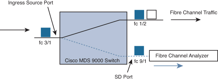
Figure 10-4 SPAN Traffic from the Ingress Direction
• Egress source (Tx): Traffic exiting the switch fabric through this source interface is spanned, or copied, to the SD port, as shown in Figure 10-5.
![]()

Figure 10-5 SPAN Traffic from the Egress Direction
The SPAN feature is available for the following interface types:
• Physical ports: These port types include F, FL, TE, E, and TL ports.
• Interface sup-fc0 (traffic to and from the supervisor):
• The Fibre Channel traffic from the supervisor module to the switch fabric through the sup-fc0 interface is called ingress traffic. It is spanned when sup-fc0 is chosen as an ingress source port.
• The Fibre Channel traffic from the switch fabric to the supervisor module through the sup-fc0 interface is called egress traffic. It is spanned when sup-fc0 is chosen as an egress source port.
• Port channels:
• All ports in the port channel are included and spanned as sources.
• You cannot specify individual ports in a port channel as SPAN sources. Previously configured SPAN-specific interface information is discarded.
• IPS module-specific Fibre Channel interfaces:
• iSCSI interfaces
• FCIP interfaces
Each SPAN session represents an association of one destination with a set of source(s) along with various other parameters that you specify to monitor the network traffic. One destination can be used by one or more SPAN sessions. You can configure up to 16 SPAN sessions in a switch. Each session can have several source ports and one destination port. To activate any SPAN session, at least one source and the SD port must be up and functioning. Otherwise, traffic is not directed to the SD port. You can temporarily deactivate (suspend) any SPAN session. The traffic monitoring is stopped during this time.
Note
A source can be shared by two sessions; however, each session must be in a different direction—one ingress and one egress.
You can perform VSAN-based filtering to selectively monitor network traffic on specified VSANs. You can apply this VSAN filter to all sources in a session. Only VSANs present in the filter are spanned. These filters are bidirectional.
An SD port has the following characteristics:
• It ignores BB_credits.
• It allows data traffic only in the egress (Tx) direction.
• It does not require a device or an analyzer to be physically connected.
• It supports only 1 Gbps or 2 Gbps speeds. The auto-speed option is not allowed. In Cisco MDS 9700 Series switches, the SD port supports 2 Gbps, 4 Gbps, 8 Gbps, and 16 Gbps speeds only.
• Multiple sessions can share the same destination ports.
• If the SD port is shut down, all shared sessions stop generating SPAN traffic.
• The outgoing frames can be encapsulated in Extended Inter-Switch Link (EISL) format.
• The SD port does not have a port VSAN.
• SD ports cannot be configured using Storage Services Modules (SSMs).
• The port mode cannot be changed if it is being used for a SPAN session. If you need to change an SD port mode to another port mode, first remove the SD port from all sessions and then change the port mode using the switchport mode command.
SPAN Configuration Example
Example 10-8 shows a sample configuration of a SPAN session.
![]()
Example 10-8 SPAN Configuration
Step 1. Configure an SD port for SPAN monitoring:
switch# configure terminal
switch(config)# interface fc9/2
switch(config-if)# switchport mode SD
switch(config-if)# switchport speed 1000
switch(config-if)# no shutdown
switch(config-if)# exit
Step 2. Configure a SPAN session:
switch(config)# span session 1
switch(config-span)# destination interface fc9/2
switch(config-span)# source interface fc7/2
switch(config-span)# source filter vsan 1-2
switch(config-span)# no shutdown
Note
Source interfaces can be VSAN, port channel, iSCSI interface, FCIP interface, interface ranges, and so on.
# To temporarily suspend or reactivate a SPAN session, you can use (no) suspend command.
switch(config-span)# (no) suspend
Step 3. Verify SPAN configuration:
switch# show span session 1
Session 1 (active)
   Destination is fc9/2
   Session filter vsans are 1-2
   Ingress (rx) sources are
     fc7/2,
   Egress (tx) sources are
     fc7/2,
Remote SPAN
The Remote SPAN (RSPAN) feature enables you to remotely monitor traffic for one or more SPAN sources distributed in one or more source switches in a Fibre Channel fabric. The SPAN destination (SD) port is used for remote monitoring in a destination switch. A destination switch is usually different from the source switch(es) but is attached to the same Fibre Channel fabric. You can replicate and monitor traffic in any remote Cisco MDS 9000 Family switch or director, just as you would monitor traffic in a Cisco MDS source switch.
The RSPAN feature is nonintrusive and does not affect network traffic switching for those SPAN source ports. Traffic captured on the remote switch is tunneled across a Fibre Channel fabric that has trunking enabled on all switches in the path from the source switch to the destination switch. The Fibre Channel tunnel is structured using trunked ISL (TE) ports. In addition to TE ports, the RSPAN feature uses two other interface types, as shown in Figure 10-6.
• SD ports: A passive port. The FC analyzer can obtain remote SPAN traffic from these passive ports.
• ST ports: SPAN tunnel (ST) ports are entry point ports in the source switch for the RSPAN Fibre Channel tunnel. ST ports are special RSPAN ports and cannot be used for normal Fibre Channel traffic.
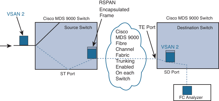
Figure 10-6 RSPAN Transmission
RSPAN has the following advantages:
• Enables nondisruptive traffic monitoring at a remote location
• Provides a cost-effective solution by using one SD port to monitor remote traffic on multiple switches
• Works with any Fibre Channel analyzer
• Is compatible with the Cisco MDS 9000 Port Analyzer adapters
• Does not affect traffic in the source switch but shares the ISL bandwidth with other ports in the fabric
An FC tunnel is a logical data path between a source switch and a destination switch. The FC tunnel originates from the source switch and terminates at the remotely located destination switch. RSPAN uses a special Fibre Channel tunnel (FC tunnel) that originates at the ST port in the source switch and terminates at the SD port in the destination switch. You must bind the FC tunnel to an ST port in the source switch and map the same FC tunnel to an SD port in the destination switch. After the mapping and binding are configured, the FC tunnel is referred to as an RSPAN tunnel, as shown in Figure 10-7.
![]()

Figure 10-7 FC and RSPAN Tunnel
ST ports have the following characteristics:
• ST ports perform the RSPAN encapsulation of the FC frame.
• ST ports do not use BB_credits.
• One ST port can be bound to only one FC tunnel.
• ST ports cannot be used for any purpose other than to carry RSPAN traffic.
• ST ports cannot be configured using Storage Services Modules (SSMs).
Exam Preparation Tasks
As mentioned in the section “How to Use This Book” in the Introduction, you have a couple of choices for exam preparation: the exercises here, Chapter 20, “Final Preparation,” and the exam simulation questions in the Pearson Test Prep software online.
Review All Key Topics
Review the most important topics in the chapter, noted with the key topic icon in the outer margin of the page. Table 10-2 lists a reference to these key topics and the page numbers on which each is found.
![]()
Table 10-2 Key Topics for Chapter 10

Define Key Terms
Define the following key terms from this chapter, and check your answers in the Glossary.
in-band
out-of-band
electrical programmable logical devices (EPLD)
Call Home
Remote Network Monitoring (RMON)
Switched Port Analyzer (SPAN)
Remote SPAN (RSPAN)
References
Cisco MDS 9000 NX-OS Software Upgrade and Downgrade Guide, Release 8.x: https://www.cisco.com/c/en/us/td/docs/switches/datacenter/mds9000/sw/8_x/upgrade/upgrade.html
Cisco MDS 9000 Family Release Notes for Cisco MDS 9000 EPLD Images, Release 8.x: https://www.cisco.com/c/en/us/td/docs/switches/datacenter/mds9000/sw/8_x/release_notes/epld/epld_rn_8x.html
Cisco MDS 9000 Series System Management Configuration Guide, Release 8.x: https://www.cisco.com/c/en/us/td/docs/switches/datacenter/mds9000/sw/8_x/config/system-management/cisco_mds9000_system_management_config_guide_8x.html
Cisco MDS 9000 Series Fundamentals Configuration Guide, Release 8.x: https://www.cisco.com/c/en/us/td/docs/switches/datacenter/mds9000/sw/8_x/config/fundamentals/cisco_mds9000_fundamentals_config_guide_8x.html