Chapter 25. Secure Network Access Control
This chapter covers the following subjects:
Network Security Design for Threat Defense: This section describes a Cisco security framework to protect networks from evolving cybersecurity threats.
Next-Generation Endpoint Security: This section describes security components such as next-generation firewalls, Web Security Appliance (WSA), and Email Security Appliance (ESA) that are part of the Cisco security framework to protect endpoints from threats and attacks.
Network Access Control (NAC): This section describes technologies such as 802.1x, Web Authentication (WebAuth), MAC Authentication Bypass (MAB), TrustSec and MACsec to enforce network access control.
In campus networks, endpoints such as mobile devices and laptops are extremely vulnerable to security threats such as malware and ransomware, and they can become infected through various means, such as phishing email, malicious websites, and infected applications. For this reason, a solid network security design protects the endpoints from these types of security threats and enforces endpoint network access control by validating the identities of end users to determine who and what they are allowed to access in the network before they are granted access. This chapter describes the components of network security design for a campus environment that are used to protect, detect, and remediate security threats and attacks.
“Do I Know This Already?” Quiz
The “Do I Know This Already?” quiz allows you to assess whether you should read the entire chapter. If you miss no more than one of these self-assessment questions, you might want to move ahead to the “Exam Preparation Tasks” section. Table 25-1 lists the major headings in this chapter and the “Do I Know This Already?” quiz questions covering the material in those headings so you can assess your knowledge of these specific areas. The answers to the “Do I Know This Already?” quiz appear in Appendix A, “Answers to the ‘Do I Know This Already?’ Quiz Questions.”
Table 25-1 “Do I Know This Already?” Foundation Topics Section-to-Question Mapping
Foundation Topics Section |
Questions |
Network Security Design for Threat Defense |
1–3 |
Next-Generation Endpoint Security |
4–7 |
Network Access Control (NAC) |
8–10 |
1. The Cisco security architectural framework is known as ______.
Cisco SEAF
Cisco Threat Grid
Cisco SAFE
Cisco Validated Designs
2. Which of the following are Cisco SAFE’s PINs in the network? (Choose all that apply.)
Internet
Data center
Branch office
Edge
Campus
Cloud
WAN
3. Cisco SAFE includes which of the following secure domains? (Choose all that apply.)
Threat defense
Segmentation
Segregation
Compliance
4. Which of the following is the Cisco threat intelligence organization?
Cisco Stealthwatch
Cisco Threat Grid
Cisco Talos
Cisco Threat Research, Analysis, and Communications (TRAC) team
5. What is the Threat Grid?
The Cisco threat intelligence organization
The Cisco sandbox malware analysis solution
The Cisco security framework
An aggregator of network telemetry data
6. Which of the following relies on NetFlow data for security analysis?
Cisco WSA
Cisco Stealthwatch
Cisco Talos
Cisco Threat Grid
7. True or false: Without Cisco ISE, it would not be possible to implement pxGrid.
True
False
8. Which of the following EAP methods supports EAP chaining?
EAP-TTLS
EAP-FAST
EAP-GTC
PEAP
9. True or false: SGT tags extend all the way down to the endpoints.
True
False
10. Which of the following three phases are defined by Cisco TrustSec? (Choose all that apply.)
Classification
Enforcement
Distribution
Aggregation
Propagation
Answers to the “Do I Know This Already?” quiz:
1 C
2 B through G
3 A, B, D
4 C
5 B
6 B
7 A
8 B
9 B
10 A, B, E
Foundation Topics
Network Security Design for Threat Defense
Evolving cybersecurity threats such as phishing, malware, ransomware, and web-based exploits are very common. There is no single product in the industry that can successfully secure organizations from all these threats. To address this, Cisco created Cisco SAFE, a security architectural framework that helps design secure solutions for the following places in the network (PINs):
Branch: Branches are typically less secure than the campus and data center PINs because the potentially large number of branches makes it cost-prohibitive to try to apply on them all the security controls found in campus and data center PINs. Branch locations are therefore prime targets for security breaches. It is important to ensure that vital security capabilities are included in the design while keeping it cost-effective. Top threats on branch PINs include endpoint malware (point-of-sale [POS] malware), wireless infrastructure exploits such as rogue APs and man-in-the-middle (MitM) attacks, unauthorized/malicious client activity, and exploitation of trust.
Campus: Campuses contain large numbers of users, including employees, contractors, guests, and partners. Campuses are easy targets for phishing, web-based exploits, unauthorized network access, malware propagation, and botnet infestations.
Data center: Data centers contain an organization’s most critical information assets and intellectual capital, and they are therefore the primary goal of all targeted threats. Data centers typically contain hundreds or thousands of servers, which makes it very difficult to create and manage proper security rules to control network access. Typical threats seen in data centers are data extraction, malware propagation, unauthorized network access (application compromise), botnet infestation (scrumping), data loss, privilege escalation, and reconnaissance.
Edge: The edge is the primary ingress and egress point for traffic to and from the Internet, and for this reason, it is the highest-risk PIN and the most important for e-commerce. Typical threats seen on the edge include web server vulnerabilities, distributed denial-of-service (DDoS) attacks, data loss, and MitM attacks.
Cloud: Security in the cloud is dictated by service-level agreements (SLAs) with the cloud service provider and requires independent certification audits and risk assessments. The primary threats are web server vulnerabilities, loss of access, data loss, malware, and MitM attacks.
Wide area network (WAN): The WAN connects the PINs together. In a large organization with hundreds of branches, managing security on the WAN is very challenging. Typical threats seen in WANs are malware propagation, unauthorized network access, WAN sniffing, and MitM attacks.
Cisco SAFE also defines secure domains, which are operational areas used to protect the different PINs. The following security concepts are used to evaluate each PIN:
Management: Management of devices and systems using centralized services is critical for consistent policy deployment, workflow change management, and keeping systems patched. Management coordinates policies, objects, and alerting.
Security intelligence: Security intelligence provides detection of emerging malware and cyber threats. It enables an infrastructure to enforce policy dynamically, as reputations are augmented by the context of new threats. This enables accurate and timely security protection.
Compliance: Examples of compliance include PCI DSS 3.0 and HIPAA.
Segmentation: Segmentation involves establishing boundaries for both data and users. Traditional manual segmentation uses a combination of network addressing and VLANs for policy enforcement. Advanced segmentation reduces operational challenges by leveraging identity-aware infrastructure to enforce policies in an automated and scalable manner.
Threat defense: It is important to have visibility into the most dangerous cyber threats. Threat defense provides this visibility through network traffic telemetry, file reputation, and contextual information (such as device types, locations, users, identities, roles, privileges levels, login status, posture status, and so on). It enables assessment of the nature and the potential risk of suspicious activity so that the correct next steps for cyber threats can be taken.
Secure services: These technologies include access control, virtual private networks (VPNs), and encryption. They include protection for insecure services (such as applications, collaboration, and wireless).
The SAFE key, shown in Figure 25-1, illustrates the PINs and security domains.

Figure 25-1 The Key to Cisco SAFE
The Cisco SAFE framework is designed to be modular. PINs that do not exist in a network can be removed.
Implementing the Cisco SAFE framework in an organization provides advanced threat defense protection that spans the full attack continuum before, during, and after an attack for all the PINs:
Before: In this phase, full knowledge of all the assets that need to be protected is required, and the types of threats that could target these assets need to be identified. This phase involves establishing policies and implementing prevention to reduce risk. Cisco solutions for this phase include next-generation firewalls, network access control, network security analysis, and identity services.
During: This phase defines the abilities and actions that are required when an attack gets through. Threat analysis and incident response are some of the typical activities associated with this phase. For this phase, organizations can leverage next-generation intrusion prevention systems, next-generation firewalls, malware protection, and email and web security solutions that make it possible to detect, block, and defend against attacks that have penetrated the network and are in progress.
After: This phase defines the ability to detect, contain, and remediate an attack. After a successful attack, any lessons learned need to be incorporated into the existing security solution. Organizations can leverage Cisco Advanced Malware Protection, next-generation firewalls, and malicious network behavior analysis using Stealthwatch to quickly and effectively scope, contain, and remediate an attack to minimize damage.
Figure 25-2 shows various Cisco products and solutions that work across the attack continuum.
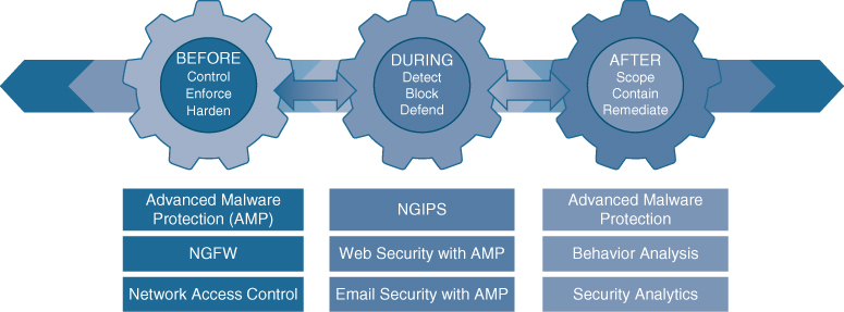
Figure 25-2 Cisco Products and Solutions Across the Attack Continuum
Next-Generation Endpoint Security
As mentioned in the introduction to this chapter, endpoints are easy targets for evolving threats, they are ubiquitous, and they come in many different forms, such as mobile devices, laptops, tablets, IP phones, personal computers (PCs), and Internet of Things (IoT) devices. Thanks to the ubiquity of bring-your-own-device (BYOD) policies, any of them can be connected to a corporate network. Organizations have used antivirus products to protect endpoints against malware for decades, and while these products have done a good job, they can’t keep up with the rapidly evolving threat landscape. Attackers have become very skilled at developing malware that can evade detection. When the effectiveness of a specific type of malware declines, attackers create new variants. Their approach is very dynamic and continuously changes at a pace that static point-in-time (for example, antivirus) tools can’t cope with. Solutions to overcome these dynamic threats require a thorough understanding of how these attacks work and the evasion techniques that allow them to infiltrate networks.
To be able to detect the rapidly evolving threats, organizations should design their networks using a security framework such as that provided by Cisco SAFE. The following sections describe the most critical components needed to implement the Cisco SAFE framework for a campus environment (or PIN, in Cisco SAFE terminology).
Cisco Talos
Talos is the Cisco threat intelligence organization, an elite team of security experts who are supported by sophisticated security systems to create threat intelligence that detects, analyzes, and protects against both known and emerging threats for Cisco products.
Cisco Talos was created from the combination of three security research teams:
IronPort Security Applications (SecApps)
The Sourcefire Vulnerability Research Team (VRT)
The Cisco Threat Research, Analysis, and Communications (TRAC) team
Talos tracks threats across endpoints, networks, cloud environments, the web, and email to provide a comprehensive understanding of cyber threats, their root causes, and scopes of outbreaks. Every day Talos receives and analyzes nearly 17 billion web requests, 300 million emails, and 1.5 million unique malware samples. Talos also receives valuable intelligence that no other cybersecurity research team can match through the following intelligence feeds:
Advanced Microsoft and industry disclosures
The Advanced Malware Protection (AMP) community
ClamAV, Snort, Immunet, SpamCop, SenderBase, Threat Grid, and Talos user communities
Honeypots
The Sourcefire Awareness, Education, Guidance, and Intelligence Sharing (AEGIS) program
Private and public threat feeds
Dynamic analysis
All this data is used to create comprehensive threat intelligence that is fed into a wide range of security products and solutions to provide protection against an extensive range of threats.
Cisco Threat Grid
Cisco Threat Grid (acquired by Cisco in 2014) is a solution that can perform static file analysis (for example, checking filenames, MD5 checksums, file types, and so on) as well as dynamic file analysis (also known as behavioral analysis) by running the files in a controlled and monitored sandbox environment to observe and analyze the behavior against millions of samples and billions of malware artifacts to determine whether it is malware or not. Behavioral analysis is combined with threat intelligence feeds from Talos as well as with existing security technologies to protect against known and unknown attacks. If Threat Grid identifies a file as malware, it begins to understand what it is doing or attempting to do, the scope of the threat it poses, and how to defend against it. Malware typically includes code to detect whether it is being analyzed in a virtual sandbox environment, and if the malware detects that it is being executed in a sandbox, it won’t run, rendering the analysis useless. However, Threat Grid evades being detected by malware by not having the typical instrumentation.
It is also possible to upload suspicious files into a sandbox environment called Glovebox to safely interact with them and observe malware behavior directly.
Threat Grid is available as an appliance and in the cloud, and it is also integrated into existing Cisco security products and third-party solutions.
Cisco Advanced Malware Protection (AMP)
Cisco Advanced Malware Protection (AMP) (formerly FireAMP) is a malware analysis and protection solution that goes beyond point-in-time detection. Using targeted, context-aware malware, attackers have the resources, persistence, time, and expertise to compromise any network relying solely on point-in-time detection mechanisms. Point-in-time detection is completely blind to the scope and depth of a breach after it happens.
Cisco AMP provides comprehensive protection for organizations across the full attack continuum:
Before: Global threat intelligence from Cisco Talos and Cisco Threat Grid feeds into AMP to protect against known and new emerging threats.
During: File reputation to determine whether a file is clean or malicious as well as sandboxing are used to identify threats during an attack.
After: Cisco AMP provides retrospection, indicators of compromise (IoCs), breach detection, tracking, analysis, and surgical remediation after an attack, when advanced malware has slipped past other defenses.
The architecture of AMP can be broken down into the following components:
AMP Cloud (private or public)
AMP connectors
AMP for Endpoints (Microsoft Windows, macOS X, Google Android, Apple iOS, and Linux)
AMP for Networks (NGFW, NGIPS, ISRs)
AMP for Email (ESA)
AMP for Web (WSA)
AMP for Meraki MX
Threat intelligence from Cisco Talos and Cisco Threat Grid
Figure 25-3 illustrates how all the AMP components come together to form the AMP architecture.
The most important component of the AMP architecture is AMP Cloud, which contains the database of files and their reputations (malware, clean, unknown, and custom), also referred to as file dispositions. The file disposition in the AMP Cloud can change based on data received from Talos or Threat Grid.
If an AMP connector uploads a sample file to AMP Cloud and the file’s reputation is deemed to be malicious, it is stored in the cloud and reported to AMP connectors that see the same file. If the file is unknown, it is sent to Threat Grid, where its behavior is analyzed in a secure sandbox environment.

Figure 25-3 AMP Components
AMP Cloud performs decision making in real time, evolving constantly based on the data that is received. AMP Cloud is capable of identifying malware on files that were previously deemed to be clean.
Unlike traditional antivirus or malware protection software that uses a local database of signatures to match malicious software or a bad file, AMP connectors remain lightweight by instead sending a hash to the cloud and allowing the cloud to make the intelligent decisions and return a verdict (about reputation or file disposition) of clean, malicious, or unknown.
Cisco AnyConnect
The Cisco AnyConnect Secure Mobility Client is a modular endpoint software product that is not only a VPN client that provides VPN access through Transport Layer Security (TLS)/Secure Sockets Layer (SSL) and IPsec IKEv2 but also offers enhanced security through various built-in modules, such as a VPN Posture (HostScan) module and an ISE Posture module. These modules enable Cisco AnyConnect to assess an endpoint’s compliance for things like antivirus, antispyware, and firewall software installed on the host. If an endpoint is found to be noncompliant, network access can be restricted until the endpoint is in compliance.
Cisco AnyConnect also includes web security through Cisco Cloud Web Security, network visibility into endpoint flows within Stealthwatch, and roaming protection with Cisco Umbrella—even while the AnyConnect client is not connected to the corporate network through a VPN. AnyConnect is supported across a broad set of platforms, including Windows, macOS, iOS, Linux, Android, Windows Phone/Mobile, BlackBerry, and ChromeOS.
Cisco Umbrella
Cisco Umbrella (formerly known as OpenDNS) provides the first line of defense against threats on the Internet by blocking requests to malicious Internet destinations (domains, IPs, URLs) using the Domain Name System (DNS) before an IP connection is established or a file is downloaded. It is 100% cloud delivered, with no hardware to install or software to maintain.
The Umbrella global network includes 30 data centers around the world using Anycast DNS, which allows it to guarantee 100% uptime. Thanks to its Anycast DNS infrastructure, it doesn’t matter where each site is physically located; DNS traffic is routed to the closest location. Security intelligence is gathered from 175 billion daily DNS requests from more than 90 million users. All this data is fed in real time into Umbrella’s massive graph database, where statistical and machine learning models are continuously run against it. This information is also constantly analyzed by the Umbrella security researchers and supplemented with intelligence from Cisco Talos.
Setting up Umbrella in the corporate network is as easy as changing the DHCP configuration on all Internet gateways (that is, routers, access points) so that all devices, including guest devices, forward their DNS traffic to Umbrella’s global network.
For devices such as laptops that are off the corporate network, if they are using the Cisco AnyConnect client, there is an option to enable a roaming security module, which allows for all DNS requests to be sent to Umbrella’s global network even when the VPN is turned off, and it does this without requiring an additional agent. Another option is to deploy the Umbrella roaming client, which tags, encrypts, and forwards DNS queries bound for the Internet to the Umbrella global network so per-device security policies can be enforced everywhere without latency or complexity.
Figure 25-4 illustrates Cisco Umbrella blocking a phishing website.
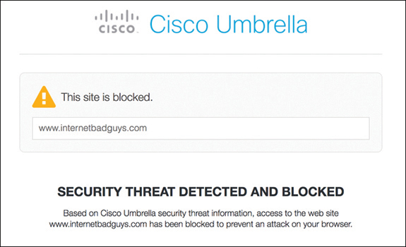
Figure 25-4 Cisco Umbrella Blocking Phishing Website
Cisco Web Security Appliance (WSA)
The Cisco Web Security Appliance (WSA) is an all-in-one web gateway that includes a wide variety of protections that can block hidden malware from both suspicious and legitimate websites. It leverages real-time threat intelligence from Cisco Talos and Cisco AMP Threat Grid that allows it to stay one step ahead of the evolving threat landscape to prevent the latest exploits from infiltrating the network. It also provides multiple layers of malware defense and vital data loss prevention (DLP) capabilities across the full attack continuum, as illustrated in Figure 25-5.
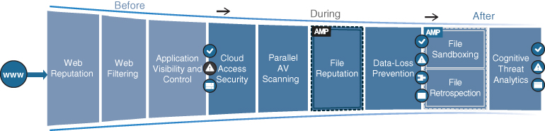
Figure 25-5 WSA Capabilities Across the Attack Continuum
The following sections describe the WSA involvement across the attack continuum before, during, and after an attack.
Before an Attack
Before an attack, the WSA actively detects and blocks potential threats before they happen by applying web reputation filters and URL filtering and by controlling web application usage:
Web reputation filters: Cisco WSA detects and correlates threats in real time by leveraging Cisco Talos. To discover where threats are hiding, Cisco Talos constantly refreshes web reputation filtering information every three to five minutes, adding intelligence to and receiving intelligence from Cisco WSA and other network security devices. Web reputation filtering prevents client devices from accessing dangerous websites containing malware or phishing links. Cisco WSA analyzes and categorizes unknown URLs and blocks those that fall below a defined security threshold. When a web request is made, web reputation filters analyze more than 200 different web traffic and network-related parameters to determine the level of risk associated with a website. After checking the domain owner, the server where the site is hosted, the time the site was created, and the type of site, the site is assigned a reputation score, which ranges from –10 to +10, instead of the binary good or bad categorizations of most malware detection applications. Based on that reputation score and selected security policies, the site is blocked, allowed, or delivered with a warning.
Web filtering: Traditional URL filtering is combined with real-time dynamic content analysis. This is used to shut down access to websites known to host malware with specific policies for URL filtering, which checks against a list of known websites from the Cisco URL filtering database of more than 50 million blocked sites. Inappropriate content is accurately identified in real time for 90% of unknown URLs using the Dynamic Content Analysis (DCA) engine. The DCA engine scans text, scores the text for relevancy, calculates model document proximity, and returns the closest category match. Every three to five minutes, Cisco Talos updates the URL filtering database with information from multiple vectors: firewalls, IPS, the web, email, and VPNs.
Cisco Application Visibility and Control (AVC): Cisco AVC identifies and classifies the most relevant and widely used web and mobile applications (such as Facebook) and more than 150,000 micro-applications (such as Facebook games or chat) to provide administrators with the most granular control over application and usage behavior. For example, AVC can be configured to permit users to access Facebook or YouTube while blocking users from activities such as clicking the “Like” button or viewing certain videos or YouTube channels.
During an Attack
During an attack, the WSA uses security intelligence from cloud access security broker (CASB) providers, Talos, and AMP for networks to identify and block zero-day threats that managed to infiltrate the network:
Cloud access security: WSA can protect against hidden threats in cloud apps by partnering with leading CASB providers (such as CloudLock) to monitor cloud app usage in real time to help combat evolving threats through intelligent protection powered by data science.
Parallel antivirus (AV) scanning: Cisco WSA enhances malware defense coverage with multiple anti-malware scanning engines running in parallel on a single appliance while maintaining high processing speeds and preventing traffic bottlenecks.
Layer 4 traffic monitoring: Cisco WSA scans all traffic, ports, and protocols to detect and block spyware “phone-home” communications with an integrated Layer 4 traffic monitor. Based on this scanning, it identifies infected clients to help stop malware that attempts to bypass classic web security solutions.
File reputation and analysis with Cisco AMP: With WSA, files are assessed using the latest threat information from Cisco Talos, which, as mentioned before, is updated every three to five minutes. Cisco WSA captures a fingerprint of each file as it traverses the gateway and sends it to AMP Cloud for a reputation verdict checked against zero-day exploits.
Data loss prevention (DLP): Cisco WSA uses Internet Control Adaptation Protocol (ICAP) to integrate with DLP solutions from leading third-party DLP vendors. By directing all outbound traffic to the third-party DLP appliance, content is allowed or blocked based on the third-party rules and policies. Deep content inspection can be enabled for regulatory compliance and intellectual property protection. Powerful engines inspect outbound traffic and analyze it for content markers, such as confidential files, credit card numbers, customer personal data, and so on and prevent this data from being uploaded into cloud file-sharing services such as iCloud and Dropbox.
After an Attack
After an attack, Cisco WSA inspects the network continuously for instances of undetected malware and breaches. After an initial detection, using Cisco AMP retrospection capabilities, Cisco WSA continues to scan files over an extended period of time, using the latest detection capabilities and collective threat intelligence from Talos and AMP Thread Grid. Alerts are sent when a file disposition changes (that is, is unknown to malware) to provide awareness and visibility into malware that evades initial defenses.
Global Threat Analytics (GTA), formerly Cognitive Threat Analytics (CTA), analyzes web traffic, endpoint data from Cisco AMP for Endpoints, and network data from Cisco Stealthwatch Enterprise. It then uses machine learning to identify malicious activity before it can exfiltrate sensitive data.
WSA can be deployed in the cloud, as a virtual appliance, on-premises, or in a hybrid arrangement. All features are available across any deployment option.
Cisco Email Security Appliance (ESA)
For business organizations, email is the most important business communication tool, and at the same time, it is one of the top attack vectors for security breaches. The Cisco Email Security Appliance (ESA) enables users to communicate securely via email and helps organizations combat email security threats with a multilayered approach across the attack continuum.
Cisco ESA includes the following advanced threat protection capabilities that allow it to detect, block, and remediate threats across the attack continuum:
Global threat intelligence: It leverages real-time threat intelligence from Cisco Talos and Cisco AMP Threat Grid.
Reputation filtering: ESA blocks unwanted email with reputation filtering, which is based on threat intelligence from Talos.
Spam protection: ESA uses the Cisco Context Adaptive Scanning Engine (CASE) to block spam emails; it delivers a spam catch rate greater than 99%, with a false-positive rate of less than 1 in 1 million.
Forged email detection: Forged email detection protects high-value targets such as executives against business email compromise (BEC) attacks.
Cisco Advanced Phishing Protection (CAPP): CAPP combines Cisco Talos threat intelligence with local email intelligence and advanced machine learning techniques to model trusted email behavior on the Internet, within organizations, and between individuals. It uses this intelligence to stop identity deception–based attacks such as fraudulent senders, social engineering, and BEC attacks.
Cisco Domain Protection (CDP): CDP for external email helps prevent phishing emails from being sent using a customer domains.
Malware defense: ESA protects against malware with Cisco AMP for Email.
Graymail detection and Safe Unsubscribe: ESA detects and classifies graymail for an administrator to take action on it if necessary. Graymail consists of marketing, social networking, and bulk messages (that is, mailing list emails). This type of email typically comes with an unsubscribe link, which may be used for phishing. Safe Unsubscribe protects against this type of phishing techniques.
URL-related protection and control: ESA protects against malicious URLs with URL filtering and scanning of URLs in attachments and shortened URLs.
Outbreak filters: Outbreak filters defend against emerging threats and blended attacks by leveraging security intelligence information from Cisco Talos. Outbreak filters can rewrite URLs included in suspicious email messages. When clicked, the new rewritten URLs redirect the email recipient to the WSA. The website content is then actively scanned, and outbreak filters display a block screen to the user if the site contains malware.
Web interaction tracking: ESA generates reports that track the end users who click on URLs that have been rewritten by the outbreak filters. The reports include the following information:
Top users who clicked on malicious URLs
The top malicious URLs clicked by end users
Date and time, rewrite reason, and action taken on the URLs
Data security for sensitive content in outgoing emails: Confidential outbound messages that match one of the more than 100 expert policies included with ESA are automatically protected by encryption, footers and disclaimers, blind carbon copies (BCCs), notifications, and quarantining.
Next-Generation Intrusion Prevention System (NGIPS)
A system that passively monitors and analyzes network traffic for potential network intrusion attacks and logs the intrusion attack data for security analysis is known as an intrusion detection system (IDS). A system that provides IDS functions and also automatically blocks intrusion attacks is known as an intrusion prevention system (IPS).
A next-generation IPS (NGIPS), according to Gartner, Inc., should include IPS functionality as well as the following capabilities:
Real-time contextual awareness
Advanced threat protection
Intelligent security automation
Unparalleled performance and scalability
Application visibility and control (AVC) and URL filtering
With the acquisition of Sourcefire in 2013, Cisco added the Firepower NGIPS to its portfolio. Firepower exceeds the requirements defined by Gartner. Following are some of the most important capabilities included with the Cisco Firepower NGIPS:
Real-time contextual awareness: Firepower discovers and provides contextual information such as applications, users, endpoints, operating systems, vulnerabilities, services, processes, network behaviors, files, and threats.
Advanced threat protection and remediation: Firepower rapidly detects, blocks, contains, and remediates advanced threats through integrated AMP for Networks and Threat Grid sandboxing solutions.
Intelligent security automation: Firepower automatically correlates threat events, contextual information, and network vulnerability data to perform the following:
Optimizing defenses by automating protection policy updates
Quickly identifying users affected by a client-side attack
Receiving alerts when a host violates a configuration policy
Detecting the spread of malware by baselining normal network traffic and detecting network anomalies
Detecting and tagging hosts that might potentially be compromised by malicious means (exploit kit, malware, command-and-control) with an IoC
Unparalleled performance and scalability: Purpose-built Firepower and ASA appliances incorporate a low-latency, single-pass design for unprecedented performance and scalability.
AVC: Firepower reduces threats through application detection of more than 4000 commercial applications, with support for custom applications.
URL filtering: Firepower provides access control to more than 80 categories of websites and covers more than 280 million individual URLs.
In addition, following are some of the capabilities available in the Cisco Firepower NGIPS that exceed the requirements for the definition of NGIPS:
Centralized management: Firepower is centrally managed by the Cisco Firepower Management Center (FMC), which is a single pane of glass for event collection and policy management.
Global threat intelligence from the Cisco Talos: Firepower integrates with Cisco Talos for up-to-the-minute IPS signature updates as well as URL filtering information to blacklist connections to or from IP addresses, URLs, and/or domain names.
Snort IPS detection engine: Firepower’s detection engine is Snort, the world’s most powerful open-source IPS engine.
High availability and clustering: Firepower can be deployed as active/standby and intra-chassis clustering and is also supported by the Firepower 9300 series platform.
Third-party and open-source ecosystem: Firepower has an open API for integration with third-party products.
Integration with Cisco ISE: The FMC can use Cisco ISE to apply remediation on compromised hosts:
Quarantine: Limits or blocks an endpoint’s access to the network
Unquarantine: Removes the quarantine
Shutdown: Shuts down the port that a compromised endpoint is attached to
Firepower NGIPS is available as the following virtual machine and physical appliances:
Firepower series appliances
Firepower Threat Defense (FTD) for ISR
NGIPS Virtual (NGIPSv)
Next-Generation Firewall (NGFW)
A firewall is a network security device that monitors incoming and outgoing network traffic and allows or blocks traffic by performing simple packet filtering and stateful inspection based on ports and protocols. A firewall essentially establishes a barrier between trusted internal networks and untrusted outside networks such as the Internet.
In addition to providing standard firewall functionality, a next-generation firewall (NGFW) can block threats such as advanced malware and application-layer attacks. According to Gartner, Inc.’s definition, a NGFW firewall must include
Standard firewall capabilities such as stateful inspection
An integrated IPS
Application-level inspection (to block malicious or risky apps)
The ability to leverage external security intelligence to address evolving security threats
Cisco integrated existing ASA firewall software with the Firepower NGIPS services software, and the combination of the two far exceeds the NGFW definition set by Gartner. This integration gave birth to the Cisco Firepower NGFW, which is the industry’s first fully integrated, threat-focused NGFW with unified management.
Firepower NGFW is available on the following hardware appliances:
Firepower series appliances
All ASA 5500-X appliances (except 5585-X)
The Firepower NGFW appliances support the following software:
ASA software image: Turns the appliance into a standard legacy firewall with no Firepower NGIPS services. Supported on all Firepower and ASA appliances.
ASA software image with Firepower Services software image (NGIPS): Runs two software images in the same appliance, with each one requiring different management applications. The Firepower services software (NGIPS) enables the ASA to be a NGFW. This type of configuration is supported only on 5500-X appliances (except the 5585-X).
Firepower Threat Defense (FTD) software image: Merges the ASA software image and the Firepower Services image into a single unified image. Supported on all Firepower and ASA 5500-X appliances (except the 5585-X).
FTD is also supported on the following platforms:
ISR modules
Firepower virtual NGFW (NGFWv) appliances, supported in VMware, KVM, Amazon Web Services (AWS), and Microsoft Azure environments
The following management options are available for NGFWs:
For FTD or Firepower Services software:
Firepower Management Center (FMC)
Firepower Device Manager (FDM) for small appliances
For ASA software:
The command-line interface (CLI)
Cisco Security Manager (CSM)
Adaptive Security Device Manager (ASDM)
Cisco Defense Orchestrator
Cisco Firepower Management Center (FMC)
The Cisco FMC is a centralized management platform that aggregates and correlates threat events, contextual information, and network device performance data. It can be used to monitor information that Firepower security devices are reporting to each other and examine the overall activity occurring in the network.
The FMC performs event and policy management for the following Firepower security solutions:
Cisco Firepower NGFW and NGFWv
Cisco Firepower NGIPS and NGIPSv
Cisco Firepower Threat Defense for ISR
Cisco ASA with Firepower Services
Cisco Advanced Malware Protection (AMP)
Cisco Stealthwatch
Cisco Stealthwatch is a collector and aggregator of network telemetry data that performs network security analysis and monitoring to automatically detect threats that manage to infiltrate a network as well as the ones that originate from within a network. Using advanced security analytics, Stealthwatch can quickly and with high confidence detect threats such as command-and-control (C&C) attacks, ransomware, DDoS attacks, illicit cryptomining, unknown malware, and inside threats. It is an agentless solution that brings threat visibility into every part of the network, including the cloud, and the only product that can detect malware in encrypted traffic and ensure policy compliance without decryption.
There are currently two offerings available for Stealthwatch:
Stealthwatch Enterprise
Stealthwatch Cloud
Cisco Stealthwatch Enterprise
Stealthwatch Enterprise provides real-time visibility into activities occurring within the network. This visibility can be scaled into the cloud, across the network, to branch locations, in the data center, and down to the endpoints.
At the core of Stealthwatch Enterprise are the Flow Rate License, the Flow Collector, Management Console, and Flow Sensor. Optional but recommended components include the following:
Cisco Stealthwatch Threat Intelligence: Enables a feed of threat intelligence from Cisco Talos
Cisco Stealthwatch Endpoint: Extends visibility into endpoints
Cisco Stealthwatch Cloud: Can be used in combination with Stealthwatch Enterprise to extend visibility into Amazon Web Services (AWS), Google Cloud Platform (GCP), and Microsoft Azure cloud infrastructures
Stealthwatch Enterprise offers the following benefits:
Real-time threat detection
Incident response and forensics
Network segmentation
Network performance and capacity planning
Ability to satisfy regulatory requirements
Stealthwatch Enterprise requires the following components:
Flow Rate License: The Flow Rate License is required for the collection, management, and analysis of flow telemetry data and aggregates flows at the Stealthwatch Management Console as well as to define the volume of flows that can be collected.
Flow Collector: The Flow Collector collects and analyzes enterprise telemetry data such as NetFlow, IP Flow Information Export (IPFIX), and other types of flow data from routers, switches, firewalls, endpoints, and other network devices. The Flow Collector can also collect telemetry from proxy data sources, which can be analyzed by Global Threat Analytics (formerly Cognitive Threat Analytics). It can also pinpoint malicious patterns in encrypted traffic using Encrypted Traffic Analytics (ETA) without having to decrypt it to identify threats and accelerate response. Flow Collector is available as a hardware appliance and as a virtual machine.
Stealthwatch Management Console (SMC): The SMC is the control center for Stealthwatch. It aggregates, organizes, and presents analysis from up to 25 Flow Collectors, Cisco ISE, and other sources. It offers a powerful yet simple-to-use web console that provides graphical representations of network traffic, identity information, customized summary reports, and integrated security and network intelligence for comprehensive analysis. The SMC is available as a hardware appliance or a virtual machine.
Optional Stealthwatch Enterprise components include the following:
Flow Sensor: Produces telemetry data for segments of the networking infrastructure that can’t generate NetFlow data and also provides visibility into the application layer data. It is available as a hardware appliance or a virtual machine.
UDP Director: Receives essential network and security information from multiple locations and then forwards it in a single data stream to one or more destinations. For example, instead of having every router in the network configured with multiple NetFlow exports for multiple destinations such as Stealthwatch Flow Collectors, LiveAction, Arbor, and so on, every router could be configured with a single NetFlow export and send the data to the UDP Director. The UDP Director takes the data and replicates the NetFlow data from all routers to the multiple destinations in single stream of data. It is available as a hardware appliance or a virtual machine.
Cisco Stealthwatch Cloud
Stealthwatch Cloud provides the visibility and continuous threat detection required to secure the on-premises, hybrid, and multicloud environments. It can accurately detect threats in real time, regardless of whether an attack is taking place on the network, in the cloud, or across both environments. Stealthwatch Cloud is a cloud-based software-as-a-service (SaaS) solution. It detects malware, ransomware, data exfiltration, network vulnerabilities, and role changes that indicate compromise.
Cisco Stealthwatch Cloud consists of two primary offerings:
Public Cloud Monitoring
Private Network Monitoring
Public Cloud Monitoring
Cisco Stealthwatch Cloud Public Cloud Monitoring provides visibility and threat detection in AWS, GCP, and Microsoft Azure cloud infrastructures. It is a SaaS-based solution that can be deployed easily and quickly.
Stealthwatch Cloud can be deployed without software agents, instead relying on native sources of telemetry such as its virtual private cloud (VPC) flow logs. Stealthwatch Cloud models all IP traffic inside VPCs, between VPCs, or to external IP addresses generated by an organization’s resources and functions. Stealthwatch Cloud is also integrated with additional AWS services such as Cloud Trail, Amazon CloudWatch, AWS Config, Inspector, Identity and Access Management (IAM), Lambda, and more.
Public Cloud Monitoring can be used in combination with Cisco Stealthwatch Enterprise to provide visibility and threat detection across the entire network.
Private Network Monitoring
Cisco Stealthwatch Cloud Private Network Monitoring provides visibility and threat detection for the on-premises network, delivered from a cloud-based SaaS solution. It is a perfect solution for organizations that want better awareness and security in their on-premises environments while reducing capital expenditure and operational overhead.
A lightweight virtual appliance needs to be installed in a virtual machine or server that can consume a variety of native sources of telemetry data or extract metadata from network packet flow. The collected metadata is encrypted and sent to the Stealthwatch Cloud analytics platform for analysis.
Private Network Monitoring is licensed based on the average monthly number of active endpoints that are monitored by Stealthwatch Cloud. An endpoint is classified as anything communicating over IP on the network.
Cisco Identity Services Engine (ISE)
Cisco Identity Services Engine (ISE) is a security policy management platform that provides highly secure network access control (NAC) to users and devices across wired, wireless, and VPN connections. It allows for visibility into what is happening in the network, such as who is connected (endpoints, users, and devices), which applications are installed and running on endpoints (for posture assessment), and much more.
Some of the most important features, benefits, services, and integrations supported by Cisco ISE include the following:
Streamlined network visibility: Through a simple web-based interface, ISE stores a detailed attribute history of all the devices, endpoints, and users (guests, employees, and contractors) on the network.
Cisco Digital Network Architecture (DNA) Center integration: Cisco DNA Center is the Cisco intent-based network controller and analytics platform. It makes it easy to design, provision, and apply policy across the network. Through its integration with Cisco ISE, it can apply TrustSec software-defined segmentation through SGT tags and Security Group Access Control Lists (SGACLs).
Centralized secure network access control: Supports the RADIUS protocol, required to enable 802.1x/EAP, MAB, and local and centralized WebAuth for consistent access control into wired, wireless, and VPN networks.
Centralized device access control: Supports the TACACS+ protocol, which is required for AAA device access control services (covered in Chapter 26, “Network Device Access Control and Infrastructure Security”).
Cisco TrustSec: Implements Cisco TrustSec policy for software-defined secure segmentation through SGT tags, SGACLs, and SXP.
Guest lifecycle management: Can be used to create customizable guest user web portals for WebAuth that can be branded with a company logo.
Streamlined device onboarding: Automates 802.1x supplicant provisioning and certificate enrollment. It also integrates with mobile device management (MDM)/enterprise mobility management (EMM) vendors for mobile device compliance and enrollment.
Internal certificate authority: Can act as an internal certificate authority.
Device profiling: Automatically detects, classifies, and associates endpoints that connect to the network to endpoint-specific authorization policies based on device type.
Endpoint posture service: Performs powerful posture audits on endpoints to make sure they are compliant. For example, it can check for the latest OS patch, see if the endpoint firewall is enabled, make sure anti-malware packages have the latest definitions, look for disk encryption, see a mobile PIN lock, determine rooted or jailbroken phone status, and much more. Devices that are not compliant can be remediated (prevented from accessing the network, applications, or services) until they become compliant. It also provides hardware inventory of every single device and endpoint connected to the network for full network visibility.
Active Directory support: Supports integration with Microsoft Active Directory 2003, 2008, 2008R2, 2012, 2012R2, and 2016.
Cisco Platform Exchange Grid (pxGrid): Shares contextual information using a single API between different Cisco platforms as well as more than 50 technology partners. pxGrid is an Internet Engineering Task Force (IETF) framework that makes it possible to automatically and quickly identify, contain, mitigate, and remediate security threats across the entire network. Cisco ISE is the central pxGrid controller (also referred to as pxGrid server), and all Cisco and third-party security platforms (referred to as pxGrid nodes) interface with it to publish, subscribe to, and query contextual information. There are two versions of pxGrid:
pxGrid 1.0: Released with ISE 1.3 and based on Extensible Messaging and Presence Protocol (XMPP)
pxGrid 2.0: Uses WebSocket and the REST API over Simple Text Oriented Message Protocol (STOMP) 1.2
Example 25-1 shows the type of contextual information Cisco ISE can share with devices integrated with it through pxGrid.
Example 25-1 Contextual Information from Cisco ISE Session Directory
Session={ip=[192.168.1.2]
Audit Session Id=0A000001000000120001C0AC
[email protected]
ADUserDNSDomain=corelab.com
ADUserNetBIOSName=corelab,
[email protected]
ADUserResolvedDNs=CN=Dewey Hyde
CN=Users
DC=corelab
DC=com
MacAddresses=[00:0C:C1:31:54:69]
State=STARTED
ANCstatus=ANC_Quarantine
SecurityGroup=Quarantined_Systems
EndpointProfile=VMWare-Device
NAS IP=192.168.1.1
NAS Port=GigabitEthernet0/0/1
RADIUSAVPairs=[ Acct-Session-Id=0000002F]
Posture Status=null
Posture Timestamp=
LastUpdateTime=Sat Aug 21 11:49:50 CST 2019
Session attributeName=Authorization_Profiles
Session attributeValue=Quarantined_Systems
Providers=[None]
EndpointCheckResult=none
IdentitySourceFirstPort=0
IdentitySourcePortStart=0
Network Access Control (NAC)
This section describes multiple network access control (NAC) technologies, such as 802.1x, MAC Authentication Bypass (MAB), and Web Authentication (WebAuth), as well as next-generation NAC technologies such as TrustSec and MACsec.
802.1x
IEEE 802.1x (referred to as Dot1x) is a standard for port-based network access control (PNAC) that provides an authentication mechanism for local area networks (LANs) and wireless local area networks (WLANs).
802.1x comprises the following components:
Extensible Authentication Protocol (EAP): This message format and framework defined by RFC 4187 provides an encapsulated transport for authentication parameters.
EAP method (also referred to as EAP type): Different authentication methods can be used with EAP.
EAP over LAN (EAPoL): This Layer 2 encapsulation protocol is defined by 802.1x for the transport of EAP messages over IEEE 802 wired and wireless networks.
RADIUS protocol: This is the AAA protocol used by EAP.
802.1x network devices have the following roles:
Supplicant: Software on the endpoint communicates and provides identity credentials through EAPoL with the authenticator. Common 802.1x supplicants include Windows and macOS native supplicants as well as Cisco AnyConnect. All these supplicants support 802.1x machine and user authentication.
Authenticator: A network access device (NAD) such as a switch or wireless LAN controller (WLC) controls access to the network based on the authentication status of the user or endpoint. The authenticator acts as the liaison, taking Layer 2 EAP-encapsulated packets from the supplicant and encapsulating them into RADIUS packets for delivery to the authentication server.
Authentication server: A RADIUS server performs authentication of the client. The authentication server validates the identity of the endpoint and provides the authenticator with an authorization result, such as accept or deny.
The 802.1x roles and components are illustrated in Figure 25-6.

Figure 25-6 802.1x Roles and Components
The EAP identity exchange and authentication occur between the supplicant and the authentication server. The authenticator has no idea what EAP type is in use; it simply takes the EAPoL encapsulated frame from the supplicant and encapsulates it within the RADIUS packet sent to the authentication server and then opens up the port if the authentication server directs it to. Therefore, the EAP authentication is completely transparent to the authenticator.
Figure 25-7 illustrates the process flow of a successful 802.1x authentication.

Figure 25-7 Successful 802.1x Authentication Process Flow
Figure 25-7 illustrates the following steps:
Step 1. When the authenticator notices a port coming up, it starts the authentication process by sending periodic EAP-request/identify frames. The supplicant can also initiate the authentication process by sending an EAPoL-start message to the authenticator.
Step 2 The authenticator relays EAP messages between the supplicant and the authentication server, copying the EAP message in the EAPoL frame to an AV-pair inside a RADIUS packet and vice versa until an EAP method is selected. Authentication then takes place using the selected EAP method.
Step 3. If authentication is successful, the authentication server returns a RADIUS access-accept message with an encapsulated EAP-success message as well as an authorization option such as a downloadable ACL (dACL). When this is done, the authenticator opens the port.
EAP Methods
There are many different EAP authentication methods available, most of them based on Transport Layer Security (TLS). Which one to choose depends on the security requirements and the EAP methods supported by the supplicants and the authentication server.
The following are the most commonly used EAP methods, which are described in this section:
EAP challenge-based authentication method
Extensible Authentication Protocol-Message Digest 5 (EAP-MD5)
EAP TLS authentication method
Extensible Authentication Protocol-Transport Layer Security (EAP-TLS)
EAP tunneled TLS authentication methods
Extensible Authentication Protocol Flexible Authentication via Secure Tunneling (EAP-FAST)
Extensible Authentication Protocol Tunneled Transport Layer Security (EAP-TTLS)
Protected Extensible Authentication Protocol (PEAP)
EAP inner authentication methods
EAP Generic Token Card (EAP-GTC)
EAP Microsoft Challenge Handshake Authentication Protocol Version 2(EAP-MSCHAPv2)
EAP TLS
EAP inner authentication methods are tunneled within PEAP, EAP-FAST, and EAP-TTLS, which are also known as outer or tunneled TLS authentication methods. Tunneled TLS authentication methods establish a TLS outer tunnel between the supplicant and the authentication server; after the encrypted tunnel is established, client authentication credentials are negotiated using one of the EAP inner methods within the TLS outer tunnel. This tunneling authentication method is very similar to the way an HTTPS session is established between a web browser and a secure website (such as a bank’s website). The HTTPS TLS tunnel is formed after the web browser validates the authenticity of the website’s certificate (one-way trust), and when the TLS tunnel is established, the user can enter the login credentials on the website through the secure TLS tunnel.
Following is a description of each of the EAP authentication methods:
EAP-MD5: Uses the MD5 message-digest algorithm to hide the credentials in a hash. The hash is sent to the authentication server, where it is compared to a local hash to validate the accuracy of the credentials. EAP-MD5 does not have a mechanism for mutual authentication; in other words, the authentication server validates the supplicant, but the supplicant does not validate the authentication server to see if it is trustworthy. This lack of mutual authentication makes it a poor choice as an authentication method.
EAP-TLS: Uses the TLS Public Key Infrastructure (PKI) certificate authentication mechanism to provide mutual authentication of supplicant to authentication server and authentication server to supplicant. With EAP-TLS, both the supplicant and the authentication server must be assigned a digital certificate signed by a certificate authority (CA) that they both trust. Because the supplicant also requires a certificate, this is the most secure authentication method; however, it is also the most difficult to deploy due to the administrative burden of having to install a certificate on the supplicant side.
PEAP: In PEAP, only the authentication server requires a certificate, which reduces the administrative burden of implementing EAP. PEAP forms an encrypted TLS tunnel between the supplicant and the authentication server. After the tunnel has been established, PEAP uses one of the following EAP authentication inner methods to authenticate the supplicant through the outer PEAP TLS tunnel:
EAP-MSCHAPv2 (PEAPv0): Using this inner method, the client’s credentials are sent to the server encrypted within an MSCHAPv2 session. This is the most common inner method, as it allows for simple transmission of username and password, or even computer name and computer password, to the RADIUS server, which can then authenticate them using Microsoft’s Active Directory.
EAP-GTC (PEAPv1): This inner method was created by Cisco as an alternative to MSCHAPv2 to allow generic authentications to virtually any identity store, including OTP token servers, LDAP, NetIQ eDirectory, and more.
EAP-TLS: This is the most secure EAP authentication since it is essentially a TLS tunnel within another TLS tunnel. It is rarely used due to its deployment complexity because it requires certificates to be installed on the supplicants.
EAP-FAST: EAP-FAST, which is similar to PEAP, was developed by Cisco Systems as an alternative to PEAP to allow for faster re-authentications and support for faster wireless roaming. Just like PEAP, EAP-FAST forms a TLS outer tunnel and then transmits the client authentication credentials within that outer TLS tunnel. A major difference between FAST and PEAP is FAST’s ability to re-authenticate faster by using protected access credentials (PACs). A PAC is similar to a secure cookie, stored locally on the host as “proof” of a successful authentication. EAP-FAST also supports EAP chaining, which is explained later in this chapter.
EAP-TTLS: EAP-TTLS is similar in functionality to PEAP but is not as widely supported as PEAP. One major difference between them is that PEAP only supports EAP inner authentication methods, while EAP-TTLS can support additional inner methods such as legacy Password Authentication Protocol (PAP), Challenge Handshake Authentication Protocol (CHAP), and Microsoft Challenge Handshake Authentication Protocol (MS-CHAP).
EAP Chaining
EAP-FAST includes the option of EAP chaining, which supports machine and user authentication inside a single outer TLS tunnel. It enables machine and user authentication to be combined into a single overall authentication result. This allows the assignment of greater privileges or posture assessments to users who connect to the network using corporate-managed devices.
MAC Authentication Bypass (MAB)
MAC Authentication Bypass (MAB) is an access control technique that enables port-based access control using the MAC address of an endpoint, and it is typically used as a fallback mechanism to 802.1x. A MAB-enabled port can be dynamically enabled or disabled based on the MAC address of the endpoint that connects to it.
Figure 25-8 illustrates the process flow of a successful MAB authentication.

Figure 25-8 Successful MAB Authentication Process Flow
The steps outlined in Figure 25-8 are listed below:
Step 1. The switch initiates authentication by sending an EAPoL identity request message to the endpoint every 30 seconds by default. After three timeouts (a period of 90 seconds by default), the switch determines that the endpoint does not have a supplicant and proceeds to authenticate it via MAB.
Step 2. The switch begins MAB by opening the port to accept a single packet from which it will learn the source MAC address of the endpoint. Packets sent before the port has fallen back to MAB (that is, during the IEEE 802.1x timeout phase) are discarded immediately and cannot be used to learn the MAC address.
After the switch learns the source MAC address, it discards the packet. It crafts a RADIUS access-request message using the endpoint’s MAC address as the identity. The RADIUS server receives the RADIUS access-request message and performs MAC authentication.
Step 3. The RADIUS server determines whether the device should be granted access to the network and, if so, what level of access to provide. The RADIUS server sends the RADIUS response (access-accept) to the authenticator, allowing the endpoint to access the network. It can also include authorization options such as dACLs, dVLANs, and SGT tags.
MAC addresses are easily spoofed, which means any endpoint can be configured to use a MAC address other than the burned-in address. For this reason, MAB authenticated endpoints should be given very restricted access and should only be allowed to communicate to the networks and services that the endpoints are required to speak to. If the authenticator is a Cisco switch, then many authorization options can be applied as part of the authorization result from the authentication server, including the following:
Downloadable ACLs (dACLs)
Dynamic VLAN assignment (dVLAN)
Security Group Tags (SGT) tags
Web Authentication (WebAuth)
In an organization, endpoints that try to connect to the network might not have 802.1x supplicants and might not know the MAC address to perform MAB. These endpoints can be employees and contractors with misconfigured 802.1x settings that require access to the corporate network or visitors and guests that need access to the Internet. For these cases, Web Authentication (WebAuth) can be used. WebAuth, like MAB, can be used as a fallback authentication mechanism for 802.1x. If both MAB and WebAuth are configured as fallbacks for 802.1x, when 802.1x times out, a switch first attempts to authenticate through MAB, and if it fails, the switch attempts to authenticate with WebAuth.
With WebAuth, endpoints are presented with a web portal requesting a username and password. The username and password that are submitted through the web portal are sent from the switch (or wireless controller, firewall, and so on) to the RADIUS server in a standard RADIUS access-request packet. In a very similar way to what occurs with MAB, the switch sends the request on behalf of the endpoint to the RADIUS server because the endpoint is not authenticating directly to the switch. Unlike MAB, WebAuth is only for users and not devices since it requires a web browser and manual username and password entry.
There are two types of WebAuth:
Local Web Authentication
Centralized Web Authentication with Cisco ISE
Local Web Authentication
Local Web Authentication (LWA) is the first form of Web Authentication that was created. For this type of WebAuth, the switch (or wireless controller) redirects web traffic (HTTP and/or HTTPS) to a locally hosted web portal running in the switch where an end user can enter a username and a password.
When the login credentials are submitted through the web portal, the switch sends a RADIUS access-request message along with the login credentials to the RADIUS server. It is important to remember that when the switch sends the login credentials on behalf of the user, it is considered to be LWA.
On Cisco switches, the LWA web portals are not customizable. Some organizations require that the web portals be customized to match their corporate branding. For those companies, LWA is not an acceptable solution.
In addition, with Cisco switches, there is no native support for advanced services such as acceptable use policy (AUP) acceptance pages (for example, a popup requesting acceptance of terms and conditions before access is allowed), password changing capabilities, device registration, and self-registration. For those advanced capabilities, a centralized web portal is required.
LWA does not support VLAN assignment; it supports only ACL assignment. It also doesn’t support the change of authorization (CoA) feature to apply new policies; therefore, access policies cannot be changed based on posture or profiling state, and even administrative changes cannot be made as a result of malware to quarantine the endpoint.
Central Web Authentication with Cisco ISE
Cisco created Centralized Web Authentication (CWA) to overcome LWA’s deficiencies. CWA supports CoA for posture profiling as well as dACL and VLAN authorization options. CWA also supports all the advanced services, such as client provisioning, posture assessments, acceptable use policies, password changing, self-registration, and device registration.
Just like LWA, CWA is only for endpoints that have a web browser, where the user can manually enter a username and a password. With CWA, WebAuth and guest VLAN functions remain mutually exclusive.
Authentication for CWA is different from authentication for LWA. The following steps detail how CWA authentication takes place:
Step 1. The endpoint entering the network does not have a configured supplicant or the supplicant is misconfigured.
Step 2. The switch performs MAB, sending the RADIUS access-request to Cisco ISE (the authentication server).
Step 3. The authentication server (ISE) sends the RADIUS result, including a URL redirection, to the centralized portal on the ISE server itself.
Step 4. The endpoint is assigned and IP address, DNS server, and default gateway using DHCP.
Step 5. The end user opens a browser and enters credentials into the centralized web portal. Unlike with LWA, the credentials are stored in ISE and are tied together with the MAB coming from the switch.
Step 6. ISE sends a re-authentication change of authorization (CoA-reauth) to the switch.
Step 7. The switch sends a new MAB request with the same session ID to ISE. ISE sends the final authorization result to the switch for the end user, including an authorization option such as a downloadable ACL (dACL).
Enhanced Flexible Authentication (FlexAuth)
By default, a Cisco switch configured with 802.1x, MAB, and WebAuth always attempts 802.1x authentication first, followed by MAB, and finally WebAuth. If an endpoint that does not support 802.1x tries to connect to the network, it needs to wait for a considerable amount of time before WebAuth is offered as an authentication option. Enhanced FlexAuth (also referred to as Access Session Manager) addresses this problem by allowing multiple authentication methods concurrently (for example, 802.1x and MAB) so that endpoints can be authenticated and brought online more quickly. Enhanced FlexAuth is a key component of the Cisco Identity-Based Networking Services (IBNS) 2.0 integrated solution, which offers authentication, access control, and user policy enforcement.
Cisco Identity-Based Networking Services (IBNS) 2.0
Cisco IBNS 2.0 is an integrated solution that offers authentication, access control, and user policy enforcement with a common end-to-end access policy that applies to both wired and wireless networks. It is a combination of the following existing features and products:
Enhanced FlexAuth (Access Session Manager)
Cisco Common Classification Policy Language (C3PL)
Cisco ISE
Cisco TrustSec
TrustSec is a next-generation access control enforcement solution developed by Cisco to address the growing operational challenges related to maintaining firewall rules and ACLs by using Security Group Tag (SGT) tags.
TrustSec uses SGT tags to perform ingress tagging and egress filtering to enforce access control policy. Cisco ISE assigns the SGT tags to users or devices that are successfully authenticated and authorized through 802.1x, MAB, or WebAuth. The SGT tag assignment is delivered to the authenticator as an authorization option (in the same way as a dACL). After the SGT tag is assigned, an access enforcement policy (allow or drop) based on the SGT tag can be applied at any egress point of the TrustSec network.
SGT tags represent the context of the user, device, use case, or function. This means SGT tags are often named after particular roles or business use cases. For example, a corporate user with a Mac that successfully authenticates via 802.1x using EAP chaining could be assigned an SGT by ISE named Mac_Corporate. If the Mac is not compliant with posture requirements because it is not owned by the corporation, then it can be assigned an SGT named Mac_Guest.
Figure 25-9 illustrates a list of default SGT tags on Cisco ISE. Notice that the SGT tags all have business-relevant names and descriptions. The SGT name is available on ISE and network devices to create policies; what is actually inserted into a Layer 2 frame SGT tag is a numeric value like the ones shown in the SGT column in decimal and hexadecimal notation.
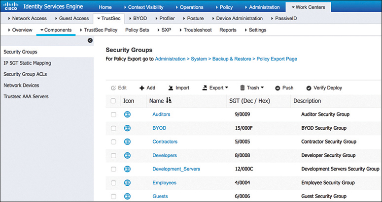
Figure 25-9 Default SGT Tags in Cisco ISE
TrustSec configuration occurs in three phases:
Ingress classification
Propagation
Egress enforcement
Ingress Classification
Ingress classification is the process of assigning SGT tags to users, endpoints, or other resources as they ingress the TrustSec network, and it can happen in one of two ways:
Dynamic assignment: The SGT is assigned dynamically and can be downloaded as an authorization option from ISE when authenticating using 802.1x, MAB, or WebAuth.
Static assignment: In environments such as a data center that do not require 802.1x, MAB, or WebAuth authentication, dynamic SGT assignment is not possible. In these cases, SGT tags can be statically mapped on SGT-capable network devices. Static assignment on a device can be one of the following:
IP to SGT tag
Subnet to SGT tag
VLAN to SGT tag
Layer 2 interface to SGT tag
Layer 3 logical interface to SGT tag
Port to SGT tag
Port profile to SGT tag
As an alternative to assigning an SGT tag to a port, Cisco ISE added the ability to centrally configure a database of IP addresses and their corresponding SGT tags. Network devices that are SGT capable can download the list from Cisco ISE.
Propagation
Propagation is the process of communicating the mappings to the TrustSec network devices that will enforce policy based on SGT tags.
There are two methods available for propagating an SGT tag—inline tagging (also referred to as native tagging) and the Cisco-created protocol SGT Exchange Protocol (SXP):
Inline tagging: With inline tagging, a switch inserts the SGT tag inside a frame to allow upstream devices to read and apply policy. Native tagging is completely independent of any Layer 3 protocol (IPv4 or IPv6), so the frame or packet can preserve the SGT tag throughout the network infrastructure (routers, switches, firewalls, and so on) until it reaches the egress point. The downside to native tagging is that it is supported only by Cisco network devices with ASIC support for TrustSec. If a tagged frame is received by a device that does not support native tagging in hardware, the frame is dropped. Figure 25-10 illustrates a Layer 2 frame with a 16-bit SGT value.
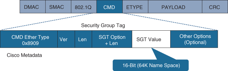
Figure 25-10 Layer 2 Ethernet Frame with an SGT Tag
SXP propagation: SXP is a TCP-based peer-to-peer protocol used for network devices that do not support SGT inline tagging in hardware. Using SXP, IP-to-SGT mappings can be communicated between non-inline tagging switches and other network devices. Non-inline tagging switches also have an SGT mapping database to check packets against and enforce policy. The SXP peer that sends IP-to-SGT bindings is called a speaker. The IP-to-SGT binding receiver is called a listener. SXP connections can be single-hop or multi-hop, as shown in Figure 25-11.
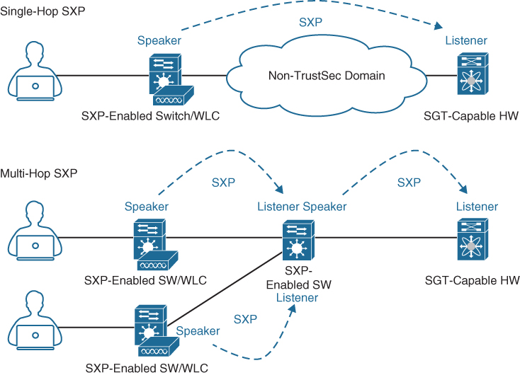
Figure 25-11 Single-Hop and Multi-Hop SXP Connections
Figure 25-12 shows an example of one access switch that supports native tagging. The packets get tagged on the uplink port and through the infrastructure. It also shows a switch that is not capable of inline tagging and that uses SXP to update the upstream switch. In both cases, the upstream switch continues to tag the traffic throughout the infrastructure.
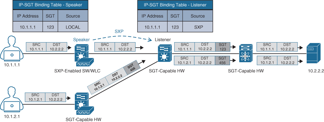
Figure 25-12 Inline Tagging and SXP Propagation
Figure 25-13 illustrates an example where a user authenticates to ISE via 802.1x. The user is connected to a switch that does not support inline tagging or SXP. This means an SGT-to-IP binding cannot be assigned to the user on the switch. The solution is for ISE to assign an SGT to the user by sending a mapping through SXP to an upstream device that supports TrustSec.

Figure 25-13 SXP Peering Between Cisco ISE and TrustSec-Capable Devices
Egress Enforcement
After the SGT tags have been assigned (classification) and are being transmitted across the network (propagation), policies can be enforced at the egress point of the TrustSec network.
There are multiple ways to enforce traffic based on the SGT tag, and they can be divided into two major types:
Security Group ACL (SGACL): Provides enforcement on routers and switches. Access lists provide filtering based on source and destination SGT tags.
Security Group Firewall (SGFW): Provides enforcement on firewalls (such as Cisco ASA and NGFW). Requires tag-based rules to be defined locally on the firewall.
Figure 25-14 illustrates how an SGACL is blocking access to traffic with an SGT valueof 123.

Figure 25-14 TrustSec Enforcement with SGACL
Figure 25-15 illustrates an SGACL egress policy production matrix from Cisco ISE that allows the defined SGACL enforcements to be visualized. The left side column represents the source SGT tags, and the top row represents the destination SGT tags. The ACL enforced is the cell within the matrix where the source and destination SGT tags meet, and the direction is always from source SGT to destination SGT. For example, the matrix shows that developers (left column) are allowed to communicate to development servers using a permit IP ACL, while all other source SGT tags are denied with a deny IP ACL. Permit IP is the equivalent of permitting all, and deny IP is the equivalent of denying all.

Figure 25-15 SGACL Production Matrix View
In addition to permit all and deny all SGACLs, more granular SGACLs are supported. Figure 25-15 also shows that employees trying to communicate with other employees will have a Permit_FTP ACL applied on egress. Figure 25-16 shows the SGACL Permit_FTP configuration on Cisco ISE, which is only allowing FTP traffic (TCP port 21) and denying all other traffic.
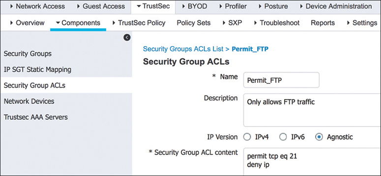
Figure 25-16 Permit FTP SGACL Contents
Figure 25-17 illustrates a scenario where only developers have access to the development servers, and any employee trying to access them is blocked. Notice that traffic is blocked on egress and not on ingress. This example also illustrates that FTP is the only protocol allowed between employees, while any other type of traffic is blocked. For the employees connected to the same switch, the switch is acting as the ingress and egress point.

Figure 25-17 SGACL Enforcement Scenario
MACsec
MACsec is an IEEE 802.1AE standards-based Layer 2 hop-by-hop encryption method; this means the traffic is encrypted only on the wire between two MACsec peers and is unencrypted as it is processed internally within the switch. This allows the switch to look into the inner packets for things like SGT tags to perform packet enforcement or QoS prioritization. MACsec also leverages onboard ASICs to perform the encryption and decryption rather than having to offload to a crypto engine, as with IPsec.
MACsec is based on the Ethernet frame format; however, an additional 16-byte MACsec Security Tag field (802.1AE header) and a 16-byte Integrity Check Value (ICV) field are added. This means that all devices in the flow of the MACsec communications must support MACsec for these fields to be used and to secure the traffic. MACsec provides authentication using Galois Method Authentication Code (GMAC) or authenticated encryption using Galois/Counter Mode Advanced Encryption Standard (AES-GCM).
Figure 25-18 illustrates the MACsec frame format and how it encrypts the TrustSec SGT tag.
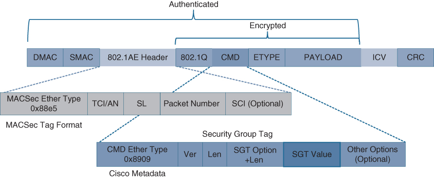
Figure 25-18 MACsec Ethernet Frame with SGT
The MACsec Security Tag fields are as follows:
MACsec EtherType (first two octets): Set to 0x88e5, designating the frame as a MACsec frame
TCI/AN (third octet): Tag Control Information/Association Number field, designating the version number if confidentiality or integrity is used on its own
SL (fourth octet): Short Length field, designating the length of the encrypted data
Packet Number (octets 5–8): The packet number for replay protection and building of the initialization vector
SCI (octets 9–16): Secure Channel Identifier, for classifying the connection to the virtual port
Two MACsec keying mechanisms are available:
Security Association Protocol (SAP): This is a proprietary Cisco keying protocol used between Cisco switches.
MACsec Key Agreement (MKA) protocol: MKA provides the required session keys and manages the required encryption keys. The 802.1AE encryption with MKA is supported between endpoints and the switch as well as between switches.
Downlink MACsec
Downlink MACsec is the term used to describe the encrypted link between an endpoint and a switch. The encryption between the endpoint and the switch is handled by the MKA keying protocol. This requires a MACsec-capable switch and a MACsec-capable supplicant on the endpoint (such as Cisco AnyConnect). The encryption on the endpoint may be handled in hardware (if the endpoint possesses the correct hardware) or in software, using the main CPU for encryption and decryption.
The Cisco switch has the ability to force encryption, make encryption optional, or force non-encryption; this setting may be configured manually per port (which is not very common) or dynamically as an authorization option from Cisco ISE (which is much more common). If ISE returns an encryption policy with the authorization result, the policy issued by ISE overrides anything set using the switch CLI.
Uplink MACsec
Uplink MACsec is the term for encrypting a link between switches with 802.1AE. By default, uplink MACsec uses Cisco proprietary SAP encryption. The encryption is the same AES-GCM-128 encryption used with both uplink and downlink MACsec.
Uplink MACsec may be achieved manually or dynamically. Dynamic MACsec requires 802.1x authentication between the switches.
Exam Preparation Tasks
As mentioned in the section “How to Use This Book” in the Introduction, you have a couple of choices for exam preparation: the exercises here, Chapter 30, “Final Preparation,” and the exam simulation questions in the Pearson Test Prep Software Online.
Review All Key Topics
Review the most important topics in the chapter, noted with the key topics icon in the outer margin of the page. Table 25-2 lists these key topics and the page number on which each is found.
Table 25-2 Key Topics for Chapter 25
Key Topic Element |
Description |
Page |
Paragraph |
Cisco SAFE places in the network (PINs) |
|
List |
Full attack continuum |
|
Section |
Cisco Talos |
|
Section |
Cisco Threat Grid |
|
Section |
Cisco Advanced Malware Protection (AMP) |
|
List |
Cisco AMP components |
|
Section |
Cisco AnyConnect |
|
Section |
Cisco Umbrella |
|
Section |
Cisco Web Security Appliance (WSA) |
|
Section |
Cisco Email Security Appliance (ESA) |
|
Paragraph |
Intrusion prevention system (IPS) |
|
List |
Next-generation intrusion prevention system (NGIPS) |
|
Paragraph |
Standard firewall |
|
List |
Next-generation firewall (NGFW) |
|
Section |
Cisco Stealthwatch |
|
List |
Cisco Stealthwatch offerings |
|
List |
Cisco Stealthwatch required components |
|
List |
Cisco Stealthwatch cloud offerings |
|
Section |
Cisco Identity Services Engine (ISE) |
|
Section |
802.1x |
|
List |
802.1x components |
|
List |
802.1x roles |
|
List |
EAP methods |
|
Section |
EAP chaining |
|
Section |
MAC Authentication Bypass (MAB) |
|
Section |
Web Authentication (WebAuth) |
|
List |
WebAuth types |
|
Section |
Cisco TrustSec |
|
List |
Cisco TrustSec phases |
|
Paragraph |
Cisco TrustSec propagation methods |
|
List |
Cisco TrustSec types of enforcement |
|
Section |
MACsec |
|
List |
MACsec keying mechanisms |
|
Section |
Downlink MACsec |
|
Section |
Uplink MACsec |
Complete Tables and Lists from Memory
Print a copy of Appendix B, “Memory Tables” (found on the companion website), or at least the section for this chapter, and complete the tables and lists from memory. Appendix C, “Memory Tables Answer Key,” also on the companion website, includes completed tables and lists you can use to check your work.
Define Key Terms
Define the following key terms from this chapter and check your answers in the Glossary:
Cisco Advanced Malware Protection (AMP)
Cisco AnyConnect Secure Mobility Client
Cisco Email Security Appliance (ESA)
Cisco Identity Services Engine (ISE)
Cisco Web Security Appliance (WSA)
Extensible Authentication Protocol (EAP)
MAC Authentication Bypass (MAB)