
Chapter 2 Legacy 802.11 Security
IN THIS CHAPTER, YOU WILL LEARN ABOUT THE FOLLOWING:
✓ Wired Equivalent Privacy (WEP) encryption
✓ Temporal Key Integrity Protocol (TKIP) Encryption
✓ Virtual Private Networks (VPNs)
Many changes to the security mechanisms of the 802.11 standard have taken place since its ratification in 1997. Three pre-RSNA or legacy security mechanisms exist: Open System authentication, Shared Key authentication, and WEP encryption. These pre-RSNA security mechanisms are currently defined in clause 11.2 of the 802.11-2012 standard. It should be noted that the current 802.11-2012 standard also defines the more current robust security network (RSN) operations that are meant to replace legacy 802.11 security. Even though these legacy security mechanisms have been superseded and should be avoided, they are still integrated into many 802.11 devices to provide backward compatibility with existing equipment. It is important to understand these security methods and to understand why Open System authentication is still valid and why Shared Key authentication and WEP encryption should be avoided.
If this chapter was strictly about legacy 802.11 security as defined by the standard, then it would be a very short chapter indeed, since Open System authentication, Shared Key authentication, and WEP encryption are the only legacy security methods originally defined by the IEEE. So why is it there is more to this chapter than just that? Well, two types of standards exist in the world of technology; de jure standards and de facto standards. Essentially de jure (Latin for “concerning law”) standards are typically defined and ratified by a standards body, such as the IEEE, whereas de facto (Latin for “concerning fact”) standards are established by practice or usage.
Over the years, different nonstandard security solutions have been implemented to enhance the wireless network security or to make up for shortcomings in the standard. Some of these, such as VPN over wireless, provided solutions to overcome flaws that arose in the standard. Others, such as MAC filtering, SSID segmentation, and SSID cloaking, provided enhancements or additional capabilities that were not in the standard. Although all of these may still have their place in some environments, for the most part, they should be avoided as the newer security mechanisms are capable of providing a faster and more secure wireless network.
Authentication
Authentication is the first of two steps required to connect to the 802.11 basic service set. Both authentication and association must occur, in that order, before an 802.11 client can pass traffic through the access point to another device on the network. Authentication is a process that is often misunderstood. When many people hear authentication, they think of what is commonly referred to as network authentication—entering a username and password in order to get access to the network. In this chapter, we are referring to 802.11 authentication that occurs at Layer 2 of the OSI model. When an 802.3 device needs to communicate with other devices, the first step is to plug the Ethernet cable into a wall jack. When this cable is plugged in, the client creates a physical link to the wired switch and is then able to start transmitting frames. When an 802.11 device needs to communicate, it must first authenticate with the access point. This authentication is not much more of a task than plugging the Ethernet cable into the wall jack. The 802.11 authentication merely establishes an initial connection between the client and the access point. The 802.11-2012 standard specifies two different methods of legacy authentication: Open System authentication and Shared Key authentication. These legacy authentication methods were not so much an authentication of user or device identity, but more of an authentication of capability. Prior to the 802.11 standard, all other wireless technology was proprietary. Think of these authentication methods as verification between the two radios that they are both valid 802.11 devices.
Open System Authentication
Open System authentication is the only pre-RSNA security mechanism that has not been deprecated. Open System authentication is the simpler of the two authentication methods. It provides authentication without performing any type of client verification. It is essentially an exchange of hellos between the client and the access point. It is considered a null authentication because there is no exchange or verification of identity between the devices. It is assumed that the devices already have all of the appropriate information to authenticate to the network. In other words, every station (STA) is validated during Open System authentication.
Within a basic service set (BSS), Open System authentication occurs with an exchange of frames between the client station and the access point station. Open System authentication utilizes a two-message authentication transaction sequence. The first message asserts identity and requests authentication. The second message returns the authentication result. If the result is “successful,” the STAs will be declared mutually authenticated. Open System authentication is also used by STAs in an independent basic service set (IBSS), which is more commonly known as an ad hoc WLAN.
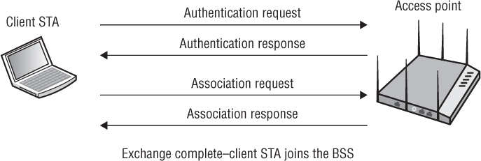
Open System authentication occurs after a client STA knows about the existence of an access point (AP) by either passive or active scanning. The client STA can passively find out about the parameters of the BSS from the AP’s beacon management frame or extract the same information during the active probing process from the AP’s probe response frame. An Open System authentication frame exchange process then begins with the goal of eventually joining the BSS. As shown in Figure 2.1, the client STA must first become authenticated before exchanging two more association frames. Once Open System authentication and association occurs, the client STA establishes a Layer 2 connection to the AP and is a member of the BSS.
FIGURE 2.1 Open System authentication
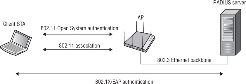
WEP encryption is optional with Open System authentication. For data privacy, Wired Equivalent Privacy (WEP) encryption can be used with Open System authentication, but WEP is used only to encrypt the Layers 3–7 MAC Service Data Unit (MSDU) payload of 802.11 data frames and only after the client station is authenticated and associated. In other words, WEP is not used as part of the Open System authentication process, but WEP encryption can be used to provide data privacy after authentication and association occur. So, if Open System authentication is so simple and basic—providing no verification of identity—then why is it still used when security is so important? The answer to this question is simple. It does not need to be secure, because other more advanced overlay security authentication methods such as 802.1X/EAP are now being implemented. As you can see in Figure 2.2, Open System authentication and association between the client STA and AP still occurs prior to the 802.1X/EAP authentication exchange between the client STA and a RADIUS server. In Exercise 2.1, you will look at a packet capture containing Open System authentication frames.
FIGURE 2.2 Open System and 802.1X/EAP authentication
NOTE
The 802.11-2012 standard now defines more advanced authentication methods. A detailed discussion about 802.1X/EAP can be found in Chapter 4, “802.1X/EAP Authentication.”
Shared Key Authentication
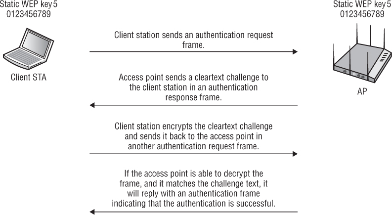
Shared Key authentication uses WEP to authenticate client stations and requires that a static WEP key be configured on both the client STA and the access point. In addition to WEP being mandatory, authentication will not work if the static WEP keys do not match. The authentication process is similar to Open System authentication but includes a challenge and response between the AP station and client station within the BSS. Shared Key authentication can also be used between two STAs in an IBSS.
Shared Key authentication is a four-way authentication frame exchange, as shown in Figure 2.3. The client station sends an authentication request to the AP, and the AP sends a cleartext challenge to the client station in an authentication response. The client station then encrypts the cleartext challenge and sends it back to the AP in the body of another authentication request frame. The AP decrypts the station’s response and compares it to the challenge text. If they match, the AP will respond by sending a fourth and final authentication frame to the station, confirming successful authentication. If they do not match, the AP will respond negatively. If the AP cannot decrypt the challenge, it will also respond negatively. If Shared Key authentication is successful, the same static WEP key that was used during the Shared Key authentication process will also be used to encrypt the 802.11 data frames.
FIGURE 2.3 Shared Key authentication exchange
Although it might seem that Shared Key authentication is a more secure solution than Open System authentication, in reality Shared Key could be the bigger security risk. Anyone who captures the cleartext challenge phrase and then captures the encrypted challenge phrase in the response frame could potentially derive the static WEP key. If the static WEP key is compromised, a whole new can of worms has been opened because now all the data frames can be decrypted.
NOTE
Do not confuse the Shared Key authentication with Preshared Key (PSK) authentication. Shared Key authentication is a legacy method defined as a pre-RSNA security method. The 802.11-2012 standard defines robust security that requires either 802.1X/EAP authentication or PSK authentication. PSK authentication methods are discussed in greater detail in Chapters 3 and 4.
In Exercise 2.1, you will look at packet captures containing encrypted and decrypted Shared Key authentication frames. Since it is our own network, and we know the WEP key, we can look at the decrypted authentication frames.
Viewing Open System and Shared Key Authentication Frames
In this exercise, you will use a protocol analyzer to view the 802.11 frame exchanges used to authenticate a client to the access point.
To perform this exercise, first download the following files from the book’s online resource area, which can be accessed at www.sybex.com/go/cwsp2e.
OPEN_SYSTEM_AUTHENTICATION.PCAP
SHARED_KEY_AUTHENTICATION_ENCRYPTED.PCAP
SHARED_KEY_AUTHENTICATION_DECRYPTED.PCAPAfter the files are downloaded, you will need packet analysis software to open these files. If you do not already have a packet analyzer installed on your computer, you can download Wireshark from www.wireshark.org.
Using the packet analyzer, open the OPEN_SYSTEM_AUTHENTICATION.PCAP file. Most packet analyzers display a list of capture frames in the upper section of the screen, with each frame numbered sequentially in the first column.
Click on packet 1. Typically in the lower section of the screen is the Packet Details pane. This section contains annotated details about the selected frame. In this pane, locate and expand the IEEE 802.11 Wireless LAN Management Frame section. Then expand the Fixed Parameters section, and note that Auth Algorithm is set to Open System and that Auth Seq Num is set to 1. This indicates that it is an Open System authentication request frame.
Click on packet 3. In the Packet Details pane, locate and expand the IEEE 802.11 Wireless LAN Management Frame section. Then expand the Fixed Parameters section, and you can see that Auth Algorithm is set to Open System and that Auth Seq Num is set to 2. This indicates that it is an Open System authentication reply frame. Also note that Status Code indicates that the authentication was successful.
Using the packet analyzer, open the SHARED_KEY_AUTHENTICATION_ENCRYPTED.PCAP file.
The two packets of most interest are packets 3 and 5. In packet 3, the access point is responding to the authentication request and it includes the unencrypted challenge text. Click on packet 3. In the Packet Details pane, locate and expand the IEEE 802.11 Wireless LAN Management Frame section. In the Tagged Parameters section, you can see the challenge text. Expand the challenge text section and note that the length of the text is 128 bytes. Also note the text that is being used.
Click on packet 5. In the Packet Details pane, locate and expand the Data section. In this section you can see 136 bytes of encrypted data. In the IEEE 802.11 Authentication section above the Data section, note the WEP parameters.
Using the packet analyzer, open the SHARED_KEY_AUTHENTICATION_DECRYPTED.PCAP file.
This file is a decrypted version of the file that you were just examining. Repeat steps 7 and 8 using the decrypted file. Packets 3 and 5 contain the challenge text and the response; however, you will not see any WEP references in packet 5, since the packet is decrypted. Also note that the challenge text and response text are identical.
Wired Equivalent Privacy (WEP) Encryption
Wired Equivalent Privacy (WEP) is a Layer 2 encryption method that uses the ARC4 streaming cipher. Because WEP encryption occurs at Layer 2, the information that is being protected is the upper Layers of 3–7. The payload of an 802.11 data frame is called the MAC Service Data Unit (MSDU). The MSDU contains data from the LLC and Layers 3–7. A simple definition of the MSDU is that it is the data payload that contains the IP packet plus some LLC data. WEP and other Layer 2 encryption methods encrypt the MSDU payload of an 802.11 data frame. The original 802.11 standard defined both 64-bit WEP and 128-bit WEP as supported encryption methods. The three main intended goals of WEP encryption include confidentiality, access control, and data integrity. The primary goal of confidentiality was to provide data privacy by encrypting the data before transmission. WEP also provides access control, which is basically a crude form of authorization. Client stations that do not have the same matching static WEP key as an access point are refused access to network resources. A data integrity checksum, known as the Integrity Check Value (ICV), is computed on data before encryption and used to prevent data from being modified. The current 802.11-2012 standard still defines WEP as a legacy encryption method for pre-RSNA security.
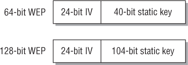
Although both 64-bit and 128-bit WEP were defined in 1997 in the original IEEE 802.11 standard, the U.S. government initially allowed the export of only 64-bit technology. After the U.S. government loosened export restrictions on key size, radio card manufacturers began to produce equipment that supported 128-bit WEP encryption. The 802.11-2012 standard refers to the 64-bit version as WEP-40 and the 128-bit version as WEP-104. As shown in Figure 2.4, 64-bit WEP uses a secret 40-bit static key, which is combined with a 24-bit number selected by the card’s device drivers. This 24-bit number, known as the initialization vector (IV), is sent in cleartext and a new IV is created for every frame. Although the IV is said to be new for every frame, there are only 16,777,216 different IV combinations; therefore, over time, you are forced to reuse the IV values. The standard also does not define what algorithm to use to create the IV. The effective key strength of combining the IV with the 40-bit static key is 64-bit encryption. 128-bit WEP encryption uses a 104-bit secret static key that is also combined with a 24-bit IV.
FIGURE 2.4 Static WEP encryption key and initialization vector
A static WEP key can usually be entered as hex characters (0–9 and A–F) or ASCII characters. The static key must match on both the access point and the client device. A 40-bit static key consists of 10 hex characters or 5 ASCII characters, whereas a 104-bit static key consists of 26 hex characters or 13 ASCII characters. Not all client stations or access points support both hex and ASCII. Some clients and access points support the use of up to four separate static WEP keys, from which a user can choose one as the default transmission key (Figure 2.5 shows an example of one such client).
FIGURE 2.5 WEP transmission key
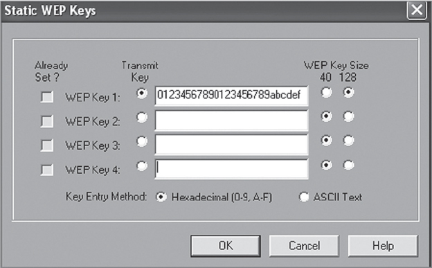
The transmission key is the static key that is used to encrypt data by the transmitting radio. A client or access point may use one key to encrypt outbound traffic and a different key to decrypt received traffic. However, each key used must match exactly on both sides of a link for encryption/decryption to work properly. When a device creates a WEP-encrypted frame, a key identifier is added to the IV field indicating which of the four possible static keys was used to encrypt the data and which key will be used to decrypt the data. As an example, if a transmitting device uses key 3 to encrypt the data, the receiving device will use key 3 to decrypt the data. If the receiving device does not have key 3 defined, or does not have the same WEP key entered in key 3, the data will not be decrypted.
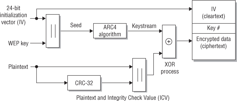
How does WEP work? WEP runs a cyclic redundancy check (CRC) on the plaintext data that is to be encrypted and then appends the Integrity Check Value (ICV) to the end of the plaintext data. The ICV is used for data integrity and should not be confused with the initialization vector (IV). A 24-bit cleartext IV is generated and combined with the static secret key. WEP then uses both the static key and the IV as seeding material through a pseudorandom algorithm that generates random bits of data known as a keystream. These pseudorandom bits are equal in length to the plaintext data that is to be encrypted. The pseudorandom bits in the keystream are then combined with the plaintext data bits by using a Boolean XOR process. The end result is the WEP ciphertext, which is the encrypted data. The encrypted data is then prefixed with the cleartext IV, along with the number of which of the four keys was used for encryption. Figure 2.6 illustrates this process.
FIGURE 2.6 WEP encryption process
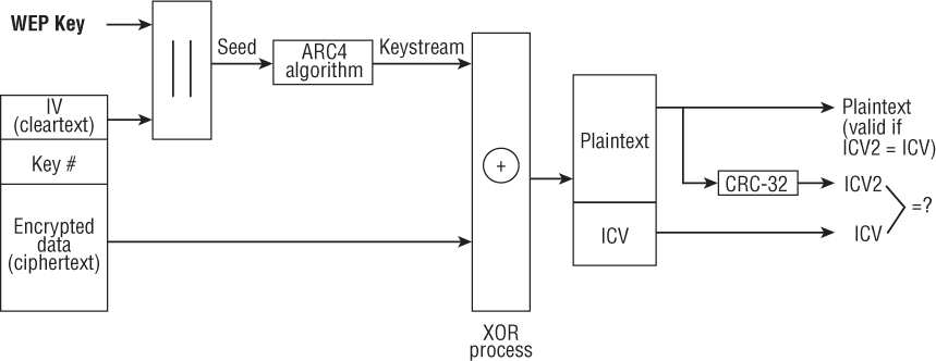
To decrypt a frame, WEP first extracts the IV and the key identifier, recognizing which key to use. WEP then uses the static key and the IV as seeding material through the pseudorandom algorithm to generate the keystream. The keystream is combined with the ciphertext using a Boolean XOR process. The end result is the decryption of the ciphertext and the creation of the plaintext data. WEP runs a CRC on the plaintext data and compares it to the decrypted ICV from the ciphertext. If the two are bit-wise identical, the frame is considered valid. Figure 2.7 illustrates this process.
FIGURE 2.7 WEP encryption process
Unfortunately, WEP has quite a few weaknesses, which is why it has been deprecated. Its weaknesses include the following four main attacks:
IV Collisions Attack Because the 24-bit initialization vector is in cleartext and a new IV is generated for every frame, all 16 million IVs will eventually be used and will be forced to repeat themselves in a busy WEP-encrypted network. Because of the limited size of the IV space, IV collisions occur and an attacker can recover the secret key much easier when IV collisions occur in wireless networks.
Weak Key Attack Because of the ARC4 key-scheduling algorithm, weak IV keys are generated. An attacker can recover the secret key much easier by recovering the known weak IV keys.
Reinjection Attack Hacker tools exist that implement a packet reinjection attack to accelerate the collection of weak IVs on a network with little traffic.
Bit-Flipping Attack The ICV data integrity check is considered weak. WEP-encrypted packets can be tampered with. Current WEP cracking tools may use a combination of the first three mentioned attacks and can crack WEP in less than 5 minutes. After an attacker has compromised the static WEP key, any data frame can be decrypted with the newly discovered key. As defined by the 802.11-2012 standard, WEP encryption is considered a legacy pre-RSNA security method. Although WEP encryption has indeed been cracked and is viewed as unacceptable in the enterprise, it is still better than using no encryption at all. If legacy WEP is the only encryption solution available, it should be deployed. Many legacy devices that only support static WEP are still deployed in enterprise environments.
Viewing Encrypted MSDU Payload of 802.11 Data Frames
In this exercise, you will use a protocol analyzer to view an FTP file transfer of a text file. You will look at the MAC Service Data Unit (MSDU) payload of 802.11 data frames.
To perform this exercise, first download the following files from the book’s online resource area, which can be accessed at www.sybex.com/go/cwsp2e.
NON_ENCRYPTED_MSDU.PCAP
ENCRYPTED_MSDU.PCAPAfter the files are downloaded, you will need packet analysis software to open these files. If you do not already have a packet analyzer installed on your computer, you can download Wireshark from www.wireshark.org.
Using the packet analyzer, open the NON_ENCRYPTED_MSDU.PCAP file. Most packet analyzers display a list of capture frames in the upper section of the screen, with each frame numbered sequentially in the first column.
Click on packet 14. Typically the Packet Details pane appears in the lower section of the screen. This section contains annotated details about the selected frame. In this window, locate and expand the Transmission Control Protocol section. In this section notice that the source port is 20 and the application is ftp-data. Further down in this section and in the hex view window, you can read the text file. The cleartext data is not encrypted and contains multiple instances of the text “These are the times that try men’s souls.”
Using the packet analyzer, open the ENCRYPTED_MSDU.PCAP file. You can now view an MSDU payload of an 802.11 data frame that is encrypted.
Click on packet 15. In the Packet Details pane, locate and expand the Data section. Notice the 636 bytes of encrypted data. All the 3–7 information of the MSDU is now encrypted and cannot be seen. Select the IEEE 802.11 Data section and expand the WEP Parameters subsection, and you can see the initialization vector (IV) and Integrity Check Value (ICV).
If you are interested in decrypting the file, you can do so by entering the WEP key into the packet analyzer software. If you are using Wireshark, click the Wireshark-Preferences menu. In the window that appears, expand the Protocols section and then scroll down and select the IEEE 802.11 protocol. Then select Enable Decryption. Next to Decryption Key, click on the Edit button and add a key type of WEP with the key value of 55:55:55:55:55 (which is the key that was used when this transmission was performed). After accepting these changes, notice that the packet capture immediately appears different. All of the encrypted packets are decrypted, with the contents fully visible. If you are using packet analyzer software other than Wireshark, you will need to check the user’s guide for that software to determine how to enter the WEP key.
TKIP
Temporal Key Integrity Protocol (TKIP) is a security protocol that was created to replace WEP. After WEP encryption was broken, 802.11 networks were left without a reliable security solution. The IEEE 802.11i security task group first defined TKIP to provide a stronger security solution without requiring users to replace their legacy equipment. Most legacy 802.11 radios could implement TKIP with a firmware upgrade, but not all legacy APs and STAs were upgradeable. The intent of TKIP was to provide a better temporary security solution until WLAN vendors could provide hardware that supported CCMP/AES encryption.
In April 2002, the Wi-Fi Alliance introduced the Wi-Fi Protected Access (WPA) certification, which requires the use of TKIP encryption. The IEEE 802.11-2012 standard defines two RSNA data confidentiality and integrity protocols: TKIP and CCMP, with TKIP support optional. Although TKIP is defined in the IEEE 802.11-2012 standard, due to security risks, it has been deprecated. TKIP still remains as an optional security protocol to provide support for older legacy devices.
TKIP is an enhancement of WEP. Like WEP, TKIP uses the ARC4 algorithm for performing its encryption and decryption processes. The TKIP enhancements were also intended to address the many known weaknesses of WEP. TKIP modifies WEP as follows:
Temporal Keys TKIP uses dynamically created encryption keys as opposed to the static keys. Any two radios use a 4-Way Handshake process to create dynamic unicast keys that are unique to those two radios. Static keys are susceptible to social engineering attacks. Dynamic encryption key generation is designed to defeat social engineering attacks.
Sequencing TKIP uses a per-MPDU TKIP sequence counter (TSC) to sequence the MPDUs it sends. An 802.11 station drops all MPDUs that are received out of order. Sequencing is designed to defeat replay and reinjection attacks that are used against WEP.
Key Mixing TKIP uses a complex two-phase cryptographic mixing process to create stronger seeding material for the ARC4 cipher. The key mixing process is designed to defeat the known IV collisions and weak-key attacks used against WEP.
Enhanced Data Integrity TKIP uses a stronger data integrity check known as the Message Integrity Code (MIC). The MIC is sometimes also referred to as the Message Integrity Check. The MIC is designed to defeat bit-flipping and forgery attacks that are used against WEP.
TKIP Countermeasures Because of the design constraints of the TKIP MIC, it is still possible for an adversary to compromise message integrity; therefore, TKIP also implements countermeasures. The countermeasures bound the probability of a successful forgery and the amount of information an attacker can learn about a key.
Figure 2.8 shows the TKIP encryption and data integrity process. You will find it helpful to refer to this figure as you read about the steps TKIP performs.
TKIP starts with a 128-bit temporal key. An often-asked question is “Where does the 128-bit temporal key come from?” The answer is that the 128-bit temporal key is a dynamically generated key that comes from a 4-Way Handshake creation process. The 128-bit temporal key can either be a pairwise transient key (PTK) used to encrypt unicast traffic or a group temporal key (GTK) used to encrypt broadcast and multicast traffic. The creation of these dynamic temporal keys is discussed in great detail in Chapter 5.
FIGURE 2.8 TKIP encryption and data integrity process
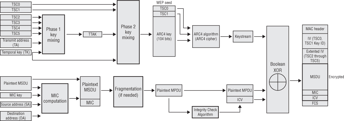
After the appropriate 128-bit temporal key (pairwise or group) is created, the two-phase key-mixing process begins. A 48-bit TKIP sequence counter (TSC) is generated and broken into 6 octets labeled TSC0 (least significant octet) through TSC5 (most significant octet). Phase 1 key mixing combines the 128-bit temporal key (TK) with the TSC2 through TSC5 octets of the TSC as well as the transmit address (TA). The TA is the MAC address of the transmitting 802.11 radio. The output of the Phase 1 key mixing is the creation of the TKIP-mixed transmit address and key (TTAK).
After the TTAK is generated, the Phase 2 key mixing can begin. Phase 2 key mixing combines the TTAK with the TSC0 and TSC1 octets of the TSC with the 128-bit TK. The output of the Phase 2 key mixing is referred to as the WEP seed. This WEP seed is then run through the ARC4 algorithm, and the keystream is created. The WEP seed is represented as a WEP IV and 104-bit WEP key when fed into the ARC4 algorithm. You may often hear TKIP referenced as using a 48-bit IV. During the Phase 2 key mixing process, TKIP encodes the TSC value from the sender as a WEP IV and an extended IV. The encoding of the 48-bit TSC effectively creates a 48-bit IV.
The two-phase key-mixing process can be summarized as follows:
TTAK = Phase 1 (TK, TA, TSC)
WEP seed = Phase 2 (TTAK, TK, TSC)
TKIP uses a stronger data integrity check known as the Message Integrity Code (MIC) to mitigate known forgery attacks against WEP. The MIC is often referred to by its nick-name of Michael. The MIC can be used to defeat bit-flipping attacks, fragmentation attacks, redirection, and impersonation attacks. The MIC is computed using the destination address (DA), source address (SA), MSDU priority, and the entire unencrypted MSDU plaintext data. After the MIC is generated, it is appended to the end of the MSDU payload. The MIC is 8 octets in size and is labeled individually as M0 through M7. The MIC contains only 20 bits of effective security strength, making it somewhat vulnerable to brute-force attacks. Because the MIC only provides weak protection against active attacks, the 802.11-2012 standard defines TKIP countermeasures procedures. The TKIP countermeasures include the following:
Logging MIC failure would indicate an active attack that should be logged. MIC failure events can then be followed up by a system administrator.
60-Second Shutdown If two MIC failures occur within 60 seconds of each other, the STA or AP must disable all reception of TKIP frames for 60 seconds. This shutdown method theoretically provides a risk of a denial-of-service (DoS) attack. In reality, there are much easier ways to perform DoS attacks.
New Temporal Keys As an additional security feature, the PTK and (in the case of the Authenticator) the GTK should be changed.
The TKIP MIC augments, but does not replace, the WEP ICV. Because the TKIP MIC is still considered weak, TKIP protects the MIC with encryption, which makes TKIP MIC forgeries more difficult. The WEP ICV helps prevent false detection of MIC failures that would cause the countermeasures to be invoked.
After the MIC is created and appended to the plaintext MSDU, the 802.11 MAC performs its normal processing on this MSDU. If fragmentation is enabled, it is possible that this could be broken up into one or more MPDUs. It is even possible for the MIC to wind up split between two MPDUs. To keep things simple, we will assume that only one MPDU is created. An integrity check is performed on the plaintext MPDU, and the WEP ICV is then appended to the MPDU. A Boolean XOR is then performed on the keystream and the MPDU/ICV to generate the encrypted payload. A frame check sequence (FCS) is calculated over all the fields of the header and entire frame body. The resulting 32-bit CRC is then placed in the FCS field.
Before verifying the MIC, a receiving 802.11 STA will check the FCS, ICV, and TSC of all MPDUs. Any MPDU that has an invalid FCS, an incorrect ICV, or a TSC value that is less than or equal to the TSC replay counter is dropped before checking the MIC. This avoids unnecessary MIC failure events. Checking the TSC before the MIC makes countermeasure-based DoS attacks harder to perform. Checking the TSC also protects against replay/injection attacks. Although considered weak for data integrity protection, the ICV also offers some error detection. If the MPDU is corrupted by multipath interference or collisions, the FCS fails and the entire MPDU must be retransmitted. After the FCS, ICV, and TSC are checked, the MIC is used for verification of data integrity.
TKIP-Encrypted Frames
In this exercise, you will use a protocol analyzer to view 802.11 data frames encrypted with TKIP.
To perform this exercise, first download the following file from the book’s online resource area, which can be accessed at www.sybex.com/go/cwsp2e.
TKIP_FRAMES.PCAP
After the file is downloaded, you will need packet analysis software to open this file. If you do not already have a packet analyzer installed on your computer, you can download Wireshark from www.wireshark.org.
Click on one of the 802.11 TKIP data packets. Typically the Packet Details pane appears in the lower section of the screen. This section contains annotated details about the selected frame. Scroll down to look at the different sections of the frame and the different fields. You will also see a TKIP Parameters section.
Click on one of the beacons with the source address of 00:1A:1E:94:4C:31. Locate and expand the IEEE 802.11 Wireless LAN Management Frame section. In this section, expand the Tagged Parameters section, and then expand Tag
 Vendor Specific Microsoft WPA Information Element. In this section, you can see TKIP listed as the cipher suite type.
Virtual Private Networks (VPNs)
Although the 802.11-2012 standard clearly defines Layer 2 security solutions, the use of upper-layer virtual private network (VPN) solutions can also be deployed with WLANs. VPNs are typically no longer recommended to provide security for WLAN client access in the enterprise due to the extra overhead from VPN encryption and the sometimes complex configuration. Furthermore, because faster, more secure Layer 2 solutions are now available for securing WLAN client access, use of Layer 3 VPNs for WLAN client access is outdated.
VPNs still have their place in Wi-Fi security and should definitely be used for remote access. They are also often used in wireless bridging environments and for branch office connectivity. Use of VPN technology is mandatory for remote access. Your end users will take their laptops off site and will most likely use public access Wi-Fi hot spots. Since there is no security at most hot spots, a VPN solution is a necessity. The VPN user will need to bring the security to the hot spot in order to provide a secure connection. It is imperative that users implement a VPN solution coupled with a personal firewall whenever accessing any public access Wi-Fi networks.
The two major types of VPN topologies are router-to-router or client/server based. Router-to-router VPNs are used to protect communications between two separate networks. Client/server VPNs are used to protect client communication to and from a network. VPNs have several major characteristics. They provide encryption, encapsulation, authentication, and data integrity. A simple definition of a Layer 3 VPN is that it is a router that also provides data privacy with encryption. VPNs use secure tunneling, which is the process of encapsulating one IP packet within another IP packet. The first packet is encapsulated inside the outer packet. The original destination and source IP address of the first packet is encrypted along with the data payload of the first packet. VPN tunneling therefore protects your original Layer 3 addresses and also protects the data payload of the original packet. Layer 3 VPNs use Layer 3 encryption; therefore, the payload that is being encrypted is the Layer 4 to 7 information. The IP addresses of the second packet are seen in cleartext and are used for communications between the tunnel end points. The destination and source IP addresses of the outer second packet will point to the virtual IP addresses of the VPN server and VPN client software.
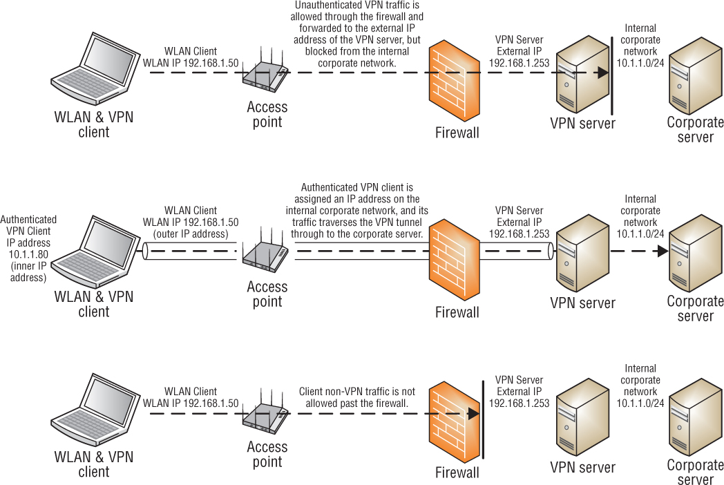
Although no longer a recommended practice, VPNs were often used for WLAN security for client access because a VPN server was already deployed within the wired infrastructure. Since the VPN server already existed, the company only needed to install the WLAN on a network with a firewall between the WLAN and the corporate network. As mentioned earlier, a Layer 3 VPN has both routing and encryption capabilities. The encryption component of the VPN is used to provide data privacy. The Layers 4–7 payload of an 802.11 data frame will be encrypted across the wireless and wired medium. The VPN client software on the WLAN client station encrypts and decrypts at one end of the tunnel and the VPN server encrypts and decrypts at the other end of the tunnel. A firewall sits between the WLAN client and the VPN server. As shown in Figure 2.9, the firewall is configured to allow only VPN traffic to pass through the firewall. Once the VPN traffic passes through the firewall, the VPN server terminates it. If the traffic is a VPN client attempting to connect, and if the client credentials are valid, the client will be authenticated and assigned an IP address on the internal network. A VPN tunnel is created between the client and the VPN server. When the VPN tunnel passes through the firewall, the tunnel terminates at the VPN server, and the traffic is decrypted and routed to network resources. The VPN provides data privacy and the firewall is used together with the VPN to segment the WLAN from network resources.
The major protocols used in Layer 3 VPN technologies are Point-to-Point Tunneling Protocol (PPTP) and Internet Protocol Security (IPsec). Unlike 802.1X/EAP solutions, an IP address is needed before a VPN tunnel can be established. A downside to using a VPN solution is that access points are potentially open to attack because a potential attacker can get both a Layer 2 and a Layer 3 connection before the VPN tunnel is established. WEP, which encrypts at Layer 2, was often used together with VPN security to protect the Layer 3 information. The problem with this strategy is that a double-encryption solution was being used, which created overhead that negatively affected the throughput and performance of the WLAN. Furthermore, as mentioned earlier in this chapter, WEP encryption can be cracked. A better solution would be 802.1X/EAP, which requires that all security credentials and transactions be completed before any Layer 3 connectivity is even possible.
FIGURE 2.9 VPN and WLAN client access security
Point-to-Point Tunneling Protocol (PPTP)
Point-to-Point Tunneling Protocol (PPTP) does not provide encryption or confidentiality, relying on the tunneled protocol to provide it. PPTP typically uses 128-bit Microsoft Point-to-Point Encryption (MPPE), which uses the ARC4 algorithm. PPTP encryption is considered adequate but not strong. PPTP uses MS-CHAP version 2 for user authentication. Unfortunately, MS-CHAP version 2 can be compromised with offline dictionary attacks, using auditing software such as Asleap. PPTP VPNs are considered to be outdated VPN technology and have been replaced with IPSec and SSL VPNs.
Layer 2 Tunneling Protocol (L2TP)
As its name implies, Layer 2 Tunneling Protocol (L2TP) is a tunneling protocol and is used to create VPNs. Like PPTP, L2TP does not provide encryption or confidentiality, relying on the tunneled protocol to provide it. IPsec is often used with L2TP to provide confidentiality, authentication, and integrity. When the two protocols are used together, they are typically referred to as L2TP/IPsec. The L2TP packets from one network are transported over IP to another network. IPsec provides a secure channel or connection between the two systems, and L2TP provides the tunnel.
Internet Protocol Security (IPsec)
Internet Protocol Security (IPsec) is a bundle of different security protocols, hashing techniques, and encryption algorithms. IPsec is flexible and allows vendors and users to select the different protocols that they want to use. IPsec VPNs use stronger encryption methods and more secure methods of authentication than PPTP. IPsec uses this assortment of protocols to perform the functions that are often linked to it. IPsec can be configured for transport mode or tunnel mode. Transport mode only encrypts the payload of the message and is typically used for host-to-host communications. In tunnel mode, the payload, header, and routing information are all encrypted, and it is typically used for gateway to gateway communications. IPsec VPNs use public and private key cryptography to establish a connection.
Internet Security Association and Key Management Protocol (ISAKMP) is a protocol that is used to establish security associations (SAs) and cryptographic keys. ISAKMP typically uses the Internet Key Exchange (IKE and IKEv2) protocol to set up SAs. SAs are unidirectional, with one SA needing to be created for each direction of the link. IKE uses a Diffie-Hellman key exchange to establish a shared session secret. Diffie-Hellman key exchange is a protocol that allows two devices to exchange a secret key across an insecure communications channel, without any prior knowledge. The type of encryption used is determined by the SA.
When configuring IPsec, you can choose Authentication Header (AH) or Encapsulating Security Payload (ESP). AH only provides authentication. As part of the authentication, AH guarantees connectionless integrity of the packets along with authentication of their data origin. This helps to protect against replay attacks. ESP is used for both encryption and authentication of the IP packet. ESP provides origin confidentiality, integrity, and authenticity of packets. It does not protect the IP packet header, but it protects the entire inner IP packet, including the header.
IPsec uses Message Digest 5 (MD5) or Secure Hash Algorithm 1 (SHA-1) hash functions in the IKE authentication. Both of these hash algorithms are cryptographically secure. These hash algorithms have evolved into what is known as Hashed Message Authentication Codes (HMAC), combining additional cryptographic functions to the algorithm. IPsec supports multiple ciphers, including Data Encryption Standard (DES), Triple DES (3DES), and Advanced Encryption Standard (AES). Device authentication is achieved by using either a server-side certificate or a preshared key.
When configuring IPsec, you must define a transform set. A transform set is a combination of the security protocols and algorithms that will be used to protect your data. This transform set is used in the configuration of the VPN server.
Secure Sockets Layer (SSL)
VPN technologies do exist that operate at other layers of the OSI model, including Secure Sockets Layer (SSL) tunneling. Unlike an IPsec VPN, an SSL VPN does not require the installation and configuration of client software on the end user’s computer. A user connects to an SSL VPN server via a web browser. The traffic between the web browser and the SSL VPN server is encrypted with the SSL protocol or Transport Layer Security (TLS). Note that SSL v3.0 has been deprecated and should no longer be used. SSL v3.0 should be replaced by TLS. TLS and SSL encrypt data connections above the Transport layer, using asymmetric cryptography for privacy and a keyed message authentication code for message reliability. Although most IPsec VPN solutions are Network Address Translation (NAT)-transversal, SSL VPNs are often chosen because of issues with NAT or restrictive firewall policies at remote locations.
VPN Configuration Complexity
As stated earlier in this chapter, the installation of a VPN is not the optimal way of securing your WLAN. There are many components that have to be installed and configured. Because most VPNs operate at Layer 3, static routes often have to be configured and advanced routing skills may be required of the administrator. The configuration would consist of a VPN server, which often is sized by the number of simultaneous connections. The VPN server would have to be configured to authenticate all of the WLAN users as they log on, so the VPN server would either need to have an internal user database, or more likely be configured to authenticate against an external database, such as a RADIUS server. If the number of clients on the WLAN grows, you might have to upgrade your VPN server or add an additional one. You may also have a firewall between the VPN server and the WLAN. This may be necessary because the WLAN itself has no security on it, allowing anyone to connect to it. You would need to have VPN software installed and configured on each wireless client, and you would have to train users how to connect to the WLAN and then log on to the VPN server using the VPN dialer.
VPN Scalability
Scaling a VPN secured WLAN compared to scaling an 802.1X/EAP secured WLAN requires more effort and resources. When scaling an 802.1X/EAP network, the addition of new users only requires an account on the authentication server and the configuration of the 802.1X client, which nowadays is often built into the operating system. The addition of new users in a VPN-secured WLAN also requires the addition of new users on the authentication server. Along with adding the user, at some point the VPN server will need to be upgraded or expanded to support the additional users. Also, the VPN client will need to be configured and installed on each of the computers that will be used to connect to the WLAN. Any firewalls that the VPN tunnel traverses will have to be configured so that the proper ports are open to allow the VPN packets to pass through. Also, if the VPN clients will need to roam across Layer 3 boundaries, the VPN tunnel will collapse. A complex MobileIP solution will have to be put in place along with the VPN infrastructure. As the size of the network grows, more resources will be used as new users are added to the network, making it a less flexible and scalable solution for WLAN client access. VPNs are rarely used anymore for WLAN client access as an enterprise solution. IPsec VPNs are mostly used to secure communications over the Internet from remote branch offices to corporate headquarters.
MAC Filters
Every network card has a physical address known as a media access control (MAC) address. This address is a 12-character hex number. 802.11 client stations, like all network-enabled devices, each have unique MAC addresses, and 802.11 access points use MAC addresses to direct frame traffic. Most vendors provide MAC filtering capabilities on their access points and WLAN controllers. MAC filters can be configured either to allow or deny traffic from specific MAC addresses.
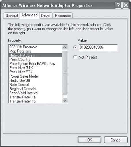
Most MAC filters apply restrictions that only allow traffic from specific client stations to pass through based on their unique MAC addresses. Any other client stations whose MAC addresses are not on the allowed list will not be able to pass traffic through the virtual port of the access point and onto the distribution system medium. It should be noted, however, that MAC addresses can be spoofed, or impersonated, and any amateur hacker can easily bypass any MAC filter by spoofing an allowed client station’s address. Many network adapters have the ability to change the MAC address as an option built into the advanced configuration window for the adapter, as shown in Figure 2.10. MAC addresses can also be very easily spoofed from the command line of many operating systems. Entering the new address and re-enabling the network card is all that is needed to change the MAC identity of the computer. Because of spoofing and because of all the administrative work that is involved with setting up MAC filters, MAC filtering is not considered a reliable means of security for wireless enterprise networks. The 802.11 standard does not define MAC filtering, and any implementation of MAC filtering is vendor specific.
FIGURE 2.10 Changing a MAC address
MAC filters are often used as a security measure to protect legacy radios that do not support stronger security. For example, older handheld barcode scanners may use 802.11 radios that support only static WEP. Best practices dictate an extra layer of security by segmenting the handheld devices in a separate VLAN with a MAC filter based on the manufacturer’s organizationally unique identifier (OUI) address (the first three octets of the MAC address that are manufacturer specific).
SSID Segmentation
Another technique to provide security in a WLAN environment using autonomous access points was through SSID and VLAN segmentation. It was common for companies to create different SSIDs for different types of users. In a WLAN environment using enterprise-class autonomous APs, SSIDs would typically be mapped to individual VLANs, and users could be segmented by the SSID/VLAN pair, all while communicating through a single access point. Each SSID could also be configured with separate security settings. As you can see in Figure 2.11, the AP would have to be configured to support VLAN tagging using a protocol such as 802.1Q, and the AP would be connected to an upstream Layer 2 or Layer 3 switch using a trunked connection. Vendors could often have as many as 16 wireless SSIDs and VLANs with the capability of segmenting the users into separate Layer 3 domains because the VLANs were mapped to unique IP subnets. It should be noted that no more than three or four SSIDs should ever be transmitted by a single radio. A unique set of beacon frames and other management frames is generated for every SSID, creating excessive MAC layer overhead. Do not go overboard and have 8, 10, or even 16 different SSIDs. The MAC Layer overhead generated by using too many SSIDs can negatively affect the throughput and performance of the WLAN.
FIGURE 2.11 SSID/VLAN/Subnet mapping
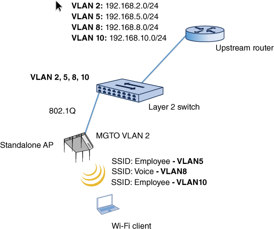
A common strategy is to create a guest, voice, and data VLAN. The SSID mapped to the guest VLAN will have captive portal authentication, and all users are restricted from corporate network resources and routed off to an Internet gateway. The SSID mapped to the voice VLAN might be using a security solution such a WPA2-Personal, and the VoWiFi client phones are routed to a VoIP server that provides QoS services through the VLAN. The SSID mapped to the data VLAN uses a stronger security solution such as WPA2-Enterprise, and the data users are allowed full access to network resources once authenticated.
SSID and VLAN segmentation is highly recommended and is discussed in more detail in Chapter 8, “WLAN Security Infrastructure.” In Chapter 12, “Wireless Security Risks,” you will also learn that multiple VLANs and access policies for different groups of users and/or devices can be assigned to a single SSID by leveraging RADIUS attributes. Assigning multiple VLANs to a single SSID is a great strategy to cut down on MAC layer overhead and airtime usage.
SSID Cloaking
Remember in Star Trek when the Romulans “cloaked” their spaceship but somehow Captain Kirk always found the ship anyway? Well, there is a way to “cloak” your SSID. Access points typically have a setting called Closed Network or Broadcast SSID. By either enabling a closed network or disabling the broadcast SSID feature, you can hide, or cloak, your wireless network name.
The service set identifier (SSID), which is also often called the extended service set identifier (ESSID), is the logical identifier, or logical name, of a WLAN. The SSID WLAN name is comparable to a Windows workgroup name. The SSID is a configurable setting on all radio cards, including access points and client stations. The SSID can be made up of as many as 32 characters and is case sensitive.
When you implement a closed network, the SSID field in the beacon frame is null (empty), and therefore passive scanning will not reveal the SSID to client stations that are listening to beacons. The idea behind cloaking the SSID is that any client station that does not know the SSID of the WLAN will not be able to associate.
Many wireless client software utilities transmit probe requests with null SSID fields when actively scanning for access points. Additionally, there are many WLAN discovery applications that can be used by individuals to discover and list nearby wireless networks.
These WLAN discovery applications also send out null probe requests actively scanning for access points. When you implement a closed network, the access point responds to null probe requests with probe responses; however, as in the beacon frame, the SSID field is null, and therefore the SSID is hidden to client stations that are using active scanning. Effectively, your wireless network is temporarily invisible, or cloaked. It should be noted that an access point in a closed network will respond to any configured client station that transmits directed probe requests with the properly configured SSID. This ensures that legitimate end users will be able to authenticate and associate to the AP. However, any station that is not configured with the correct SSID will not be able to authenticate or associate. Although implementing a closed network will indeed hide your SSID from WLAN discovery tools, anyone with a WLAN protocol analyzer can capture the frames transmitted by any legitimate end user and discover the SSID, which is transmitted in cleartext. In Exercise 2.4 you will search through a packet capture to see some of the different types of frames that include the SSID, even when it is hidden. In other words, a hidden SSID can usually be found in seconds with a WLAN protocol analyzer. Many wireless professionals will argue that hiding the SSID is a waste of time, whereas others view a closed network as just another layer of security. Cloaking the SSID usually keeps the SSID hidden from most WLAN discovery tools that use null probe requests. However, some of the WLAN discovery tools use alternate methods of discovering an SSID and may be able to display the SSID of a hidden network.
Although you can hide your SSID to cloak the identity of your WLAN from novice hackers (often referred to as script kiddies) and nonhackers, do not consider SSID cloaking as a WLAN security solution. The 802.11-2012 standard does not define SSID cloaking, and therefore all implementations of a closed network are vendor specific. As a result, incompatibility can potentially cause connectivity problems. Some wireless clients will not connect to a hidden SSID, even when the SSID is manually entered in the client software. Therefore, be sure to know the capabilities of your devices before implementing a closed network. Cloaking the SSID can also become an administrative and support issue. Requiring end users to configure the SSID in the radio software interface often results in more calls to the help desk because of misconfigured SSIDs. We highly recommended that you never cloak your SSID and instead broadcast your SSID for anyone and everyone to see.
Viewing Hidden SSIDs
In this exercise, you will use a protocol analyzer to view a 70-second packet capture. You will search through this packet capture for the name of a hidden SSID. You will see that even though an SSID is hidden, it is contained in many different types of packets and can be easily found.
To perform this exercise, first download the following file from the book’s online resource area, which can be accessed at www.sybex.com/go/cwsp2e.
CWSP_HIDDEN2_SSID.PCAP
After the files are downloaded, you will need packet analysis software to open this file. If you do not already have a packet analyzer installed on your computer, you can download Wireshark from www.wireshark.org.
Using the packet analyzer, open the CWSP_HIDDEN2_SSID.PCAP file. Most packet analyzers display a list of capture frames in the upper section of the screen, with each frame numbered sequentially in the first column.
Click on packet 1, which is a beacon frame. In the Packet Details pane, expand the IEEE 802.11 Wireless LAN Management Frame section. Then expand the Tagged Parameters section. Notice that the Tag: SSID parameter set displays Broadcast instead of an SSID.
Click on packet 58, which is a null probe request from a client station. In this frame you will see that the Tag: SSID parameter set also displays Broadcast. The client is sending a null probe request looking for any and all access points. Now click on packet 59, which is the probe response frame from the AP. In the frame you will again see that the Tag: SSID parameter set displays Broadcast since the AP is cloaking the SSID.
Search through the packet capture for the CWSP-Hidden2 SSID. Even though it is hidden, it is still transmitted in many frames. If you are using Wireshark, select Edit
Find Packet from the menu. You want to search for the string CWSP-Hidden2. Remember, SSIDs are case sensitive, so you want to make sure that you type it correctly, and you may want to click the Case Sensitive option. If you deselected this option, you do not have to be exact with the entry’s letter case.After you have entered the SSID that you are searching for, click the Find button and the program will highlight the next frame that matches your search. Every time you click the Find button, the program will find the next frame that contains the SSID. These are frame exchanges between the AP and legitimate clients that are preconfigured with the SSID.
![]() Real World Scenario
Real World Scenario
The simple answer to this question is yes if the situation warrants the use of legacy security. Legacy devices are still being used on many WLANs. Some of these legacy devices that do not support WPA or WPA2 are still deployed in the enterprise. Common examples are older wireless barcode scanners and other handheld or specialty hardware devices that still only support static WEP encryption. The preferred scenario is to replace all of the legacy devices with new devices that support WPA2-Enterprise or at least WPA2-Personal. However, budgetary reasons often prevent an upgrade to newer and better devices. The bottom line is that some security is better than no security. If static WEP encryption is the strongest solution available, it should still be used even though WEP has been cracked.
An often-quoted security model is the concept of the “lowest hanging fruit.” If someone walks up to an apple tree and wants an apple to eat, they will usually pick an apple that is at eye level and within arm’s reach. They will probably not pick an apple that is hanging from a branch 20 feet above the ground. Think of a WLAN using no security as an apple within arm’s reach and think of a WLAN using WEP encryption as an apple that is on a branch 20 feet from ground level. The passing individual can still get a ladder if they really want the apple that is 20 feet in the air, but chances are they will ignore the higher apple and still choose to pick an apple that is within arm’s reach. If a hacker is determined to crack WEP, they will do it. However, if WEP is used on legacy devices, the hacker may try to access a WLAN with no security as opposed to the WLAN using WEP.
If you are using legacy security, we highly recommend that you segment the legacy devices in a separate VLAN with a separate SSID. We also suggest restricting access so that the wireless devices are limited to performing only the tasks that they require and limiting access to anywhere else on the network. Some legacy devices do not even support static WEP. Those devices should also be put in a separate VLAN on a separate SSID and a MAC filter should be used for security. Any hacker can get around a MAC filter, but at least the apple is higher on the tree.
Summary
In this chapter, you learned about the de jure and de facto standards that have been used to secure legacy 802.11 networks. We discussed Open System and Shared Key authentication and why Shared Key authentication should no longer be used. We also looked at the encryption and decryption processes of WEP and explained some of its shortcomings that have led to it being deprecated.
It is important to remember that, although VPN technology is widely used and a recommended technology to provide secure communications between networks and between individual clients and networks, it has fallen out of favor for securing WLAN users. The reason for this is because easier and faster security solutions are available that require less configuration and can scale up better. VPN solutions can still provide secure access for a WLAN, but with an ease, speed, and growth penalty when compared to an 802.1X/EAP solution. It is important to remember that over the years, in attempts to provide more security to the WLAN, vendors have included many features with their products to allow users to try to secure their networks. MAC filters and SSID cloaking are two legacy features that are both easily bypassed. Both techniques add a level of inconvenience to the network, to the user, and to a potential intruder, but neither adds any level of additional security.
SSID segmentation is one of the legacy security solutions that, if properly configured, has provided security to the network. By integrating SSIDs with VLANs, the flow of traffic can be controlled and isolated.
Exam Essentials
Understand pre-RSNA authentication methods. Be able to explain the differences between Open System authentication and Shared Key authentication.
Describe the WEP encryption and decryption process. Explain the components and process used to encrypt and decrypt a WEP packet. Identify and describe each of the fields that make up a WEP-encrypted 802.11 data frame.
Understand VPN technology and how it is used in a WLAN. Know the differences between the types of VPN technology that have been used with WLANs. Know the benefits and detriments of each.
Define other non-802.11 WLAN security mechanisms. Explain the other non-802.11 security mechanisms, such as MAC filters, SSID segmentation, and SSID cloaking.
Review Questions
1. Before an 802.11 client STA can pass traffic through the AP, which two of the following must occur? (Choose two answers.)
A. 802.1X
B. EAP
C. Association
D. Authentication
E. WEP keys must match
2. Which of the following is contained in a WEP-encrypted frame? (Choose all that apply.)
A. IV in cleartext format
B. IV in encrypted format
C. Key identifier
D. WEP key in encrypted format
E. 64-bit initialization vector
3. 128-bit WEP encryption uses a user-provided static key of what size?
A. 64 bits
B. 104 bits
C. 104 bytes
D. 128 bits
E. 128 bytes
4. When SSID cloaking is enabled, which of the following occurs? (Choose all that apply.)
A. The SSID field is set to null in the beacon frame.
B. The SSID field is set to null in the probe request frame.
C. The SSID field is set to null in the probe response frame.
D. The AP stops transmitting beacon frames.
E. The AP stops responding to probe request frames.
5. Which technologies use the RC4 or ARC4 cipher? (Choose all that apply.)
A. Static WEP
B. Dynamic WEP
C. PPTP
D. L2TP
E. MPPE
6. Which of the following is not defined by the 802.11-2012 standard? (Choose all that apply.)
A. WEP
B. VPN
C. MAC filtering
D. SSID segmentation
E. SSID cloaking
7. 802.11 pre-RSNA security defines which wireless security solution?
A. Dynamic WEP
B. 802.1X/EAP
C. 64-bit static WEP
D. Temporal Key Integrity Protocol (TKIP)
E. CCMP/AES
8. Which of the following have been deprecated in the 802.11-2012 standard? (Choose all that apply.)
A. Wired Equivalent Privacy
B. Temporal Key Integrity Protocol
C. Point-to-Point Tunneling Protocol
D. Shared Key authentication
E. Open System authentication
9. Peter is configuring a standalone AP to provide segmentation of three groups of wireless user traffic on the corporate network. Which deployment strategies will reach this goal? (Choose all that apply.)
A. Create three separate SSIDs, one for each group, and have each SSID linked with a separate VLAN.
B. Create a trunk for each of the VLANs between the AP and the access layer switch.
C. Create a single trunk for all of the VLANs between the AP and the access layer switch.
D. Configure each of the SSIDs with the same encryption keys for easier management and administration.
E. Configure each of the SSIDs with different encryption keys.
F. Consider leveraging RADIUS attributes to assign different groups of users and devices to different VLANS tied to the same SSID.
10. Evan has configured a laptop and an AP, each with two WEP keys. WEP key 1 is the same on both devices, and WEP key 2 is the same on both devices. He configured the laptop to use WEP key 1 to encrypt its data. He configured the AP to use WEP key 2 to encrypt its data. Will this configuration work?
A. No, since there is only one WEP key on each device.
B. No, since the value of the WEP key must be identical on both the laptop and the AP.
C. Yes, as long as the value of WEP key 1 is identical on both computers and the value of WEP key 2 is identical on both computers.
D. Yes. The laptop and AP will only use the first WEP key, so as long as the value of these keys is identical, the configuration will work.
E. Yes. The laptop and AP will attempt to use each of the WEP keys when decrypting a frame.
11. Laura is attempting to diagnose a WLAN by using a packet analyzer to capture the exchange of frames and packets between a wireless client and the AP. In the process of analyzing the packets, she sees two 802.11 authentication frames, two 802.11 association frames, and DHCP requests and responses, and then she begins to see encrypted data. Which of the following could the client be using? (Choose all that apply.)
A. Open System authentication
B. Shared Key authentication
C. 802.1X/EAP
D. WEP
E. IPsec
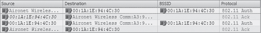
12. This graphic shows a packet capture of a successful 802.11 authentication. In which of the following types of client connections could this authentication not occur? (Choose all that apply.)
A. 802.1X/EAP
B. WEP with Shared Key authentication
C. WEP with Open System authentication
D. Open System authentication with WEP
13. This graphic shows a WLAN discovery tool screen capture. How many SSIDs are configured with cloaking enabled? (Choose all that apply.)
A. None
B. At least ten
C. One
D. Ten
E. Exact number cannot be determined
14. 128-bit WEP encryption uses an IV and a static key. What are the lengths of these?
A. 64 bit IV and 64 bit key
B. 24 bit IV and 104 bit key
C. 28 bit IV and 100 bit key
D. 20 bit IV and 108 bit key
E. None of the above
15. The graphic shows a packet capture of a successful 802.11 authentication. In which of the following types of client connections could this not occur?
A. 802.1X/EAP
B. WEP with Shared Key authentication
C. WEP with Open System authentication
D. Unencrypted with Open System authentication
16. Which hash algorithms can be used in the IKE authentication process? (Choose all that apply.)
A. Diffie-Hellman
B. MS-CHAPv2
C. MD5
D. ISAKMP
E. SHA-1
17. Which of these temporal keys are used by TKIP/ARC4 encryption? (Choose all that apply.)
A. PMK
B. PTK
C. GTK
D. GMK
E. 256-bit, 256-bit
18. Which of these authentication methods is the most secure?
A. Open System authentication with WEP
B. Open System authentication without WEP
C. Shared Key authentication
D. 802.1X/EAP authentication
19. Which of the following specifications are true for an SSID? (Choose all that apply.)
A. Up to 20 characters.
B. Up to 32 characters.
C. Case sensitive.
D. Spaces are allowed.
E. Spaces are not allowed.
20. Which 802.11 Layer 2 protocol is used for authentication in an 802.1X framework?
A. Extensible Authentication Protocol
B. Extended Authentication Protocol
C. MS-CHAP
D. Open System
E. Shared Key