
Chapter 14 Wireless Security Monitoring
IN THIS CHAPTER, YOU WILL LEARN ABOUT THE FOLLOWING:
✓ Wireless intrusion detection and prevention systems (WIDS and WIPS)
✓ 802.11w
Wireless intrusion monitoring has evolved since its creation in 2006. Today most systems have methods to prevent and mitigate several of the better known wireless attacks. While most systems are distributed for scalability across a large enterprise, single laptop versions of intrusion monitoring systems also exist. Initially, wireless intrusion monitoring existed at Layer 2. Now Layer 1 wireless intrusion monitoring systems are also available to scan for potential Layer 1 attacks. A large-scale enterprise WLAN requires more than spot checks with handheld scanners and laptop-based tools. Although many of these tools have state-of-the-art detection and mitigation, by themselves they are not going to offer the needed level of 24-hour daily monitoring or security. Spot checks or mobile scans can be a vital part of a security plan and can even help you to meet the bare minimum of some security standards. However, by themselves they leave much to be desired as a total solution. Large enterprises require a distributed solution with centralized management capabilities and 24/7/365 monitoring capabilities. Distributed monitoring solutions may also have prevention capabilities, including mitigating rogue APs and clients. The use of distributed WLAN monitoring and rogue prevention reduces the time and expense required to maintain a healthy and secure wireless network.
Wireless Intrusion Detection and Prevention Systems (WIDS and WIPS)
When people think of wireless networking, they tend to think only in terms of access and not in terms of attacks or intrusions. However, it has become increasingly necessary to monitor constantly for many types of WLAN attacks because of the potential damage they can cause. Businesses of all sizes deploy 802.11 wireless networks for mobility and access. Many of these networks are running a wireless intrusion detection system (WIDS) to monitor for attacks. Because many organizations are worried about the potential damage that results from rogue access points, it is not unusual for a company to deploy a WIDS prior to deploying the WLAN. Most WIDS vendors prefer to call their product a wireless intrusion prevention system (WIPS). The reason that they refer to their products as prevention systems is that all of them are now capable of mitigating attacks from rogue access points and or rogue clients.
Wireless intrusion detection systems and wireless intrusion prevention systems share many common features that help administrators and security staff members alike in the maintenance and protection of WLAN traffic. WIDS and WIPS both use a combination of sensors and management systems in the gathering and analysis of wireless traffic. Some use information gained from integration with managed switches and WLAN controllers as well as information reported from access points. The key thing to understand about WIDS and WIPS is that they use the same information that an auditor or an administrator would gather using laptop-based tools or handheld devices to conduct an audit, but they do so 24 hours per day using a distributed methodology. A WIDS solution gathers information from the 802.11 radio transmissions detected by multiple sensors and then correlates the captured information. A distributed WIDS solution offers the scalability that cannot be provided by an auditor with a single protocol analyzer.
WIPS act in a similar manner, with the additional capability of being able to keep rogue stations off legitimate WLANs, and some even help keep rogue APs off the wired network. Some WIPS are also able to enforce WLAN policy to stop authorized stations from engaging in unauthorized behaviors, such as connecting to unauthorized APs, forming ad hoc connections, and communicating without using approved authentication and encryption methods. Their names describe their functions; a WIDS detects and notifies about potential attacks or vulnerabilities, whereas a WIPS functions as a WIDS and additionally protects the WLAN using various methods beyond simple detection and notification.
WIDS/WIPS Infrastructure Components
The components of a WIDS/WIPS and their abilities vary from manufacturer to manufacturer. However, their core functions and hardware are similar. The typical WIDS/WIPS solution is a distributed client/server model that consists of two primary components:
WIDS/WIPS server
Sensors
A WIDS/WIPS server acts as a central point for monitoring security and performance data collection. A WIDS/WIPS server is often a standalone device that is available as either a hardware appliance or as a software appliance that can run as a virtual machine. The WIDS/WIPS server might also be integrated in a WLAN controller. WIDS/WIPS server monitoring capabilities can also be unified with a network management server (NMS) solution that is used to monitor all aspects of a WLAN. These WLAN security servers may be deployed in a datacenter as an on-premises solution or exist in a cloud-based environment.
The server can use signature analysis, behavior analysis, protocol analysis, and RF spectrum analysis to detect potential threats. Signature analysis looks for patterns associated with common WLAN attacks. Behavior analysis looks for 802.11 anomalies. Protocol analysis dissects the MAC layer information from 802.11 frames. Protocol analysis may also look at the Layer 3–7 information of 802.11 data frames that are not encrypted. Spectrum analysis monitors RF statistics, such as signal strength and signal-to-noise ratio (SNR). Performance analysis can be used to gauge WLAN health statistics, such as capacity and coverage.
Some solutions might additionally require a software-based management console that is used to communicate back to a WIDS/WIPS server from a desktop station. The management console is the software interface used for administration and configuration of the server and sensors. The management console can also be used for 24/7 monitoring of 802.11 wireless networks. However, the majority of the WIDS/WIPS solutions do not require an additional console and all security monitoring is viewed directly from the server. As shown in Figure 14.1, a WLAN administrator can monitor all of the potential WLAN security threats from the graphical user interface (GUI) of the WIDS/WIPS server.
FIGURE 14.1 WIDS/WIPS monitoring

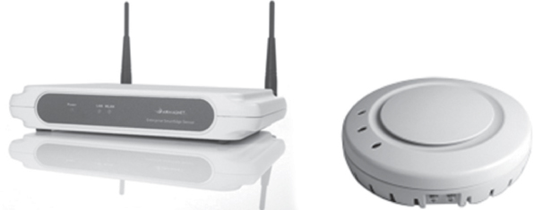
Hardware or software-based sensors may be placed strategically to listen to and capture all 802.11 communications. Sensors are the eyes and ears of a WIDS/WIPS monitoring solution. Sensors use 802.11 radios to collect information used in securing and analyzing WLAN traffic. As shown in Figure 14.2, WIDS/WIPS sensors use 802.11 radio chipsets and most often the same hardware as 802.11 access points. However, dedicated sensors are tasked with being a listening device rather than an AP that provides client access. Sensors constantly scan across all 14 channels of the 2.4 GHz ISM band as well as all channels of the 5 GHz UNII frequency bands. Although rarely used in WLAN deployments, some channels in the 4.9 GHz range—which is reserved for public safety in the United States but is a common channel band in Japan—may also be monitored. The channel scanning interval is usually set at a fixed rate between 100 ms and 1 second. However, the channel scanning interval can be adjusted for shorter or longer times. Usually sensors are set to continuously scan across all 802.11 channels. Sensors can also be configured to monitor only a single fixed channel. The majority of WIDS/WIPS sensors are hardware based. Some WIDS/WIPS solutions offer sensor software that can be installed on a computer. The sensor software can then use the computer’s 802.11 radio for scanning. Figure 14.2 shows hardware sensors from two different WIPS vendors.
FIGURE 14.2 WIDS/WIPS hardware sensors
Communications from the sensors back to the server can be either be a standards-based management protocol such as Control and Provisioning of Wireless Access Points (CAPWAP) or a proprietary management protocol. The management protocol is normally protected by an encrypted Secure Sockets Layer (SSL) tunnel. Typically, a sensor also sends a continuous heartbeat message back to the WIPS server to indicate that the sensor is still functional. Sensors can usually be centrally managed from the server or may be managed individually through Telnet, SSH, or a web browser. Most WIPS use port 443 for SSL communications; port 443 will need to be open on any firewall located between a sensor and the WIDS/WIPS server. Depending on the vendor, other vendor-specific ports may also need to be open to permit communications between the sensors and the WIDS/WIPS server. Sensors may also be used for remote packet capturing.
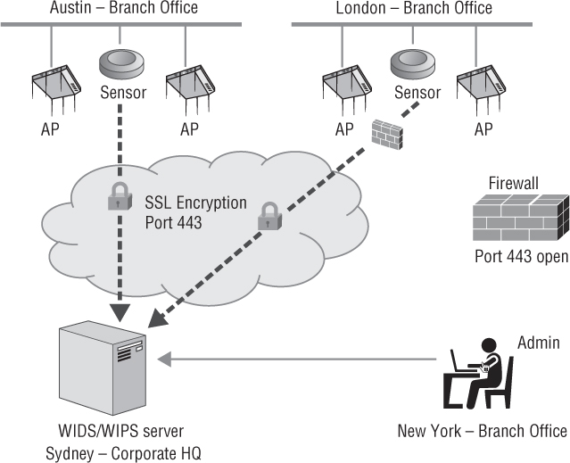
As shown in Figure 14.3, the two components of the WIDS/WIPS distributed design can exist at a single WLAN enterprise site or can scale to monitor multiple WLAN sites across a wide area network (WAN). The WIDS/WIPS server might reside in Sydney, Australia, while the WLANs that are being monitored may reside in Austin and London. The administrator monitoring the WIPS solution can access the server across the Internet from anywhere in the world.
FIGURE 14.3 Distributed WIDS/WIPS
WIDS/WIPS Architecture Models
The components of a WLAN security monitoring solution are usually deployed within one of the two major WIDS/WIPS architectures:
Overlay
Integrated
As Figure 14.4 shows, an overlay WIDS/WIPS architecture is deployed on top of the existing wireless network. This model uses an independent vendor’s WIDS/WIPS solution and can be deployed to monitor any preexisting or planned WLAN. The overlay systems typically have more extensive features and monitoring capabilities, but they are usually more expensive. The overlay solution consists of a WIPS server and sensors that are not part of the WLAN solution that provides access to clients.
An overlay solution uses standalone sensors to monitor the preexisting WLAN. Standalone sensors use dedicated radios that function only as sensors and are not used as APs. The standalone sensors, also known as dedicated sensors, require their own cable to run and communicate back to the WIDS/WIPS server over the IP network. Usually, standalone sensors can use a single 802.11 dual-band radio to monitor both the 2.4 GHz ISM band and the 5 GHz UNII bands.
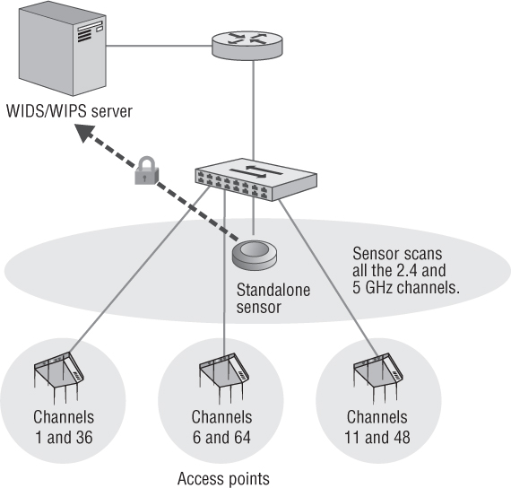
Standalone sensors may also have two radios: one dedicated to monitor the 2.4 GHz channels and another dedicated to monitor the 5 GHz channels. Sensors used in overlay WIPS architecture are normally independent of the WLAN being used to provide access. However, WLAN vendor access points can often integrate software code that can be used to convert the APs into standalone sensors that will communicate with the third-party WIDS/WIPS server. Overlay solutions increase hardware and deployment costs but generally offer more functionality and security. Overlay WIDS/WIPS servers typically use a wider range of attack signatures to recognize potential threats and collect more information for WLAN health analysis. Another major advantage of the overlay model is that if the WLAN goes down, the WIDS/WIPS monitoring continues because the overlay solution is independent of the WLAN infrastructure.
In the early days of Wi-Fi deployments, overlay WIDS/WIPS solutions were deployed with autonomous APs. Over the years, integrated WIDS/WIPS solutions have become much more commonplace mainly due to the cost savings. Overlay WIDS/WIPS solutions are now primarily used in enterprise verticals that can afford an overlay WLAN security monitoring solution. Overlay WIDS/WIPS are still often used in verticals such as federal government, military, financial industries and big-box retailers.
Most WLAN vendors now offer an integrated WIDS/WIPS architecture to provide both client access and security monitoring. An integrated architecture requires the APs to function as WIPS sensors while also providing 802.11 connectivity and access to WLAN clients. The device that functions as a WIDS/WIPS server within an integrated model depends on the WLAN architecture that is deployed. If a centralized WLAN architecture is deployed, typically the WLAN controller also operates as the WIDS/WIPS server. The controller-based APs, which also function as sensors, are centrally managed and monitored from the WLAN controller. If a distributed WLAN design is deployed, normally a network management server (NMS) is tasked with WIPS/WIPS server duties. The distributed APs, which also function as sensors, are centrally managed and monitored from the NMS. The NMS can be either a cloud-based solution or an on-premises solution.
As shown in Figure 14.5, APs used in an integrated WIPS architecture have the capability to be converted to full-time sensors. Instead of providing access to clients, the APs scan all channels, continuously listening for attacks, just like a dedicated sensor model. The form factors of the APs that are used for integrated WIPS sensors vary widely depending on the WLAN vendor. Many APs use a software-defined radio (SDR) that has the ability to operate either as a 2.4 GHz transceiver or as a 5 GHz transceiver, but it cannot transmit on both frequency bands at the same time. However, if the SDR uses a dual-frequency chipset, a single radio access point that has been converted into a full-time sensor can listen to both the 2.4 GHz and 5 GHz frequency bands. Many APs have two radios, both of which can be converted to a sensor. One radio can monitor the 2.4 GHz channels while the other radio monitors the 5 GHz channels. An AP with two radios could also be used to provide access on a single frequency band while the other radio is used as a full-time sensor to scan the channels of both bands. Some APs deployed in an integrated WIPS architecture have three radios. One radio is used for 2.4 GHz client access, another radio is used for 5 GHz client access, and a third SDR is used to monitor both frequency bands.
FIGURE 14.5 Integrated WIDS/WIPS
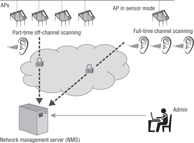
APs used in an integrated WIPS architecture can also function as part-time sensors. In this case, access points use off-channel scanning procedures for dynamic RF spectrum management purposes. For example, an AP that is providing client access on channel 6 will also monitor other channels where the AP does not transmit. The AP might stay on channel 6 for 10 seconds. During the 10-second interval, the AP is capable of sending transmissions to an associated client as well as receiving transmissions from an associated client. After the 10-second interval, the AP will listen off-channel on channel 7 for 110 ms. The AP will then return to channel 6 for 10 seconds and then go off-channel to monitor channel 8 for 110 ms. This round-robin method of off-channel scanning is used by the APs to listen for the beacon frame transmissions of other access points as well as to monitor for any other RF transmissions off-channel. How often an AP spends on-channel and scans off-channel is dependent on the WLAN vendor. Based on all the RF monitoring from multiple access points, there might be dynamic changes to the AP’s channel and transmit power settings. Although the main purpose of off-channel scanning is to provide dynamic RF capabilities, the off-channel scanning also allows the APs to function as part-time sensors for the WIDS/WIPS server module in the WLAN controller or NMS. The off-channel scanning used by the APs effectively provides time slicing between AP and sensor functionality.
Time slicing between AP and sensor functionality may reduce hardware and deployment expense, but it offers limited detection and prevention. The majority of customers of WLAN vendors opt not to incur the extra expense of deploying APs as full-time sensors and only use the part-time, time-slicing capabilities of the access points. If you hired a security guard to watch the main entrance to your place of business, would you want the security guard to take a break for 55 minutes every hour and only watch the main gate for 5 minutes of each hour? An attacker might recognize that a WIPS solution is only using part-time sensors. The attacker could then launch a brief attack during the period that the APs are providing access. The attack occurs when the APs are not performing off-channel scanning and the attack is therefore not detected.
Another problem with part-time sensors is that they may suspend off-channel scanning if a VoWiFi phone is associated with the access point. Off-channel scanning is notorious for causing “choppy audio” during an active voice call from a VoWiFi device associated to an AP. Most WLAN vendors now have an option that suspends off-channel scanning based on the detection of QoS priority markings that indicate voice traffic. Effectively off-channel scanning is suspended during an active VoIP call over the WLAN. If the off-channel scanning is suspended due to VoWiFi communications, the WLAN security monitoring is also suspended.
An additional problem with part-time sensor use is wireless rogue containment, which will be discussed later in this chapter. If a time slicing AP/sensor must go off-channel for an extended period of time to contain a rogue device, the AP is not on its home channel providing access to clients. It should be noted, however, that many WLAN vendors support a configuration setting that prevents a time slicing AP/sensor from performing wireless rogue containment when clients are associated.
Although the APs act as part-time sensors for the integrated WIPS server, it is also a highly recommended practice to deploy some APs or AP radios as full-time sensors when using an integrated WIDS/WIPS server solution.
It should be noted that either an overlay or integrated WIPS architecture can very often interface with other security solutions that might be vital to the WLAN design. As shown in Figure 14.6, the WIPS solution might also interoperate with enterprise security and management (SIEM) platforms and mobile device management (MDM) platforms. SNMP and Syslog interfaces can also be used to integrate event and log management tools.
FIGURE 14.6 Integration with other security solutions

Multiple Radio Sensors
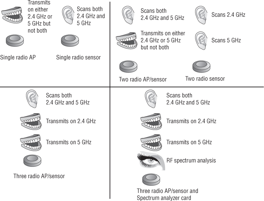
As Figure 14.7 shows, the latest innovations in WLAN security monitoring use multiple radio devices that are not locked to a frequency, protocol, or function. This innovative technique allows a single cable drop to be used, thereby reducing deployment costs; a single housing to be used, thus reducing hardware costs; and multiple radios to be used in the housing, thereby increasing functionality. A device with three radios can use one radio for 2.4 GHz coverage, one radio for 5 GHz coverage, and the third radio as a sensor to monitor and scan both bands. In a mesh deployment, one radio can be used as a 2.4 GHz AP for local coverage, one can be used for a 5 GHz mesh back-haul connection, and a third can be used as a sensor for the coverage area. Some WLAN vendors are even making 802.11 devices with three radios along with a modular spectrum analyzer sensor used for RF spectrum analysis. Multiple radio devices allow WLAN coverage and WIDS/WIPS on separate dedicated radios, increasing security and WLAN performance monitoring abilities at a reduced expense. As mentioned earlier, the form factors of the APs that are used for integrated WIPS sensors vary widely depending on the WLAN vendor.
FIGURE 14.7 Multiple 802.11 radio devices
Sensor Placement
Sensor placement is an often-discussed topic when deploying a WIDS/WIPS solution. The question that is always asked is, “How many sensors do I need?” The answer often depends on the budget and the value of the network resources that are being protected by WLAN security monitoring. The best answer is that you can never have too many sensors. When WLAN security monitoring is deployed, the more ears the better.
Every WLAN vendor has its own sensor deployment recommendations and guidelines; however, a ratio of one sensor for every three-to-five access points is highly recommended. As shown in Figure 14.8, full-time sensors are often placed strategically at the intersection points of three AP coverage cells. A common mistake is placing the sensors in a straight line as opposed to staggered sensor arrangement (which will assure a wider area of monitoring). Another common sensor placement recommendation is to arrange sensors around the perimeter of the building. Perimeter placement increases the effectiveness of triangulation and also helps to detect WLAN devices that might be outside the building. Some of the better WLAN predictive modeling software solutions will also create models for recommended sensor placement.

If an integrated WIDS/WIPS solution is deployed, all access points are deployed as part-time sensors. Once again, it is strongly recommended to deploy some full-time sensors with an integrated solution. When WLAN security monitoring is an extremely high priority and cost is not an issue, the more sensor devices the better. WIDS/WIPS deployments at military bases often follow a ratio of one sensor for every two APs or may even deploy sensors with a 1:1 ratio.
Device Classification
Although the upper-layer payload of 802.11 data frames is usually encrypted, the Layer 2 information remains exposed to allow for MAC layer communications to occur. All Layer 2 information is captured and analyzed by WIDS/WIPS solutions. Any 802.11-based device transmitting within the hearing range of a sensor will eventually be detected as the sensor sweeps the channels. WIDS/WIPS can also integrate with WLAN controllers, APs, and access layer switches pulling information from them for use in detecting wired devices. Information freely available in 802.11 management frames will allow the WIDS/WIPS initially to determine if an 802.11 device is an access point, client station, or ad hoc client station. If an 802.11 wireless device is transmitting within the hearing range of a sensor, it will be detected by the WIDS/WIPS and then will be classified, as shown in Figure 14.9.
FIGURE 14.9 WIDS/WIPS device classification
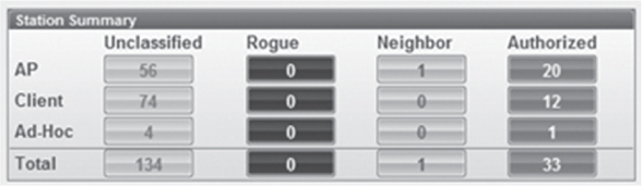
Most WIDS/WIPS vendors categorize access points and client stations in four or more classifications. Wi-Fi vendors may have different names for the various classifications, but most solutions classify 802.11 radios as follows:
Authorized Device This classification refers to any client station or access point that is an authorized member of the company’s wireless network. An overlay WIDS/WIPS solution usually requires initial manual input to classify radios as authorized infrastructure devices. A network administrator can manually label each radio as an infrastructure device after detection from the WIPS or can import a list of all the company’s client MAC addresses into the system. Devices may also be authorized in bulk from a comma-delimited file. Integrated solutions automatically classify any APs as authorized devices. An integrated solution will also automatically classify client stations as authorized if the client stations are properly authenticated.
Unauthorized Device The unauthorized device classification is assigned automatically to any new 802.11 radios that have been detected but not classified as rogues. Unknown devices are considered to be unauthorized and are usually investigated further to determine whether they are a neighbor’s device or a potential future threat. Unauthorized devices may later be manually classified as a known neighbor device.
Neighbor Device This classification refers to any client station or access point that is detected by the WIPS and whose identity is known. This type of device initially is detected as an unauthorized device. The neighbor device label is then typically assigned manually by an administrator. Devices manually classified as known are most often 802.11 access points or client radio devices of neighboring businesses that are not considered a threat.
Rogue Device The rogue classification refers to any client station or access point that is considered an interfering device and a potential threat. Most WIDS/WIPS solutions define rogue access points as devices that are actually plugged into the wired network backbone and are not known or managed by the organization. Most of the WIDS/WIPS vendors use a variety of methods to determine whether a rogue access point is actually plugged into the wired infrastructure.
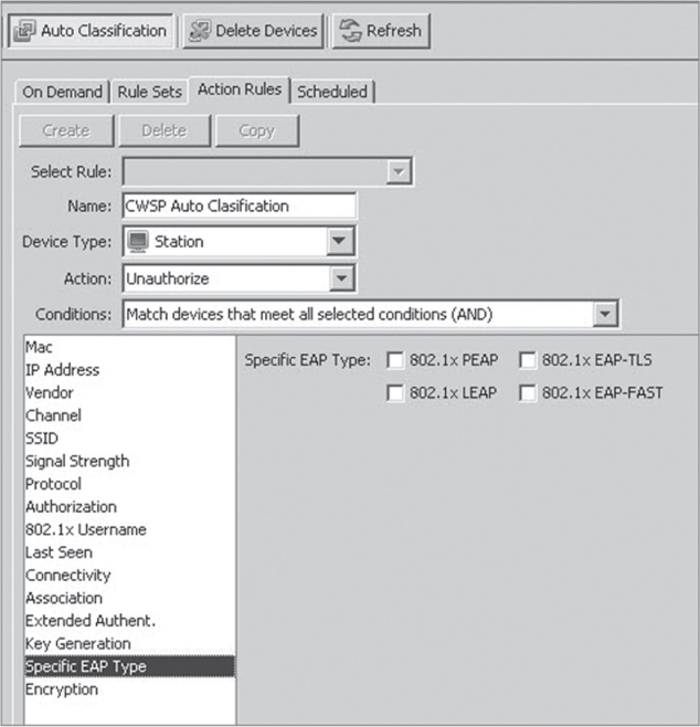
Many WIDS/WIPS solutions also have the ability to conduct auto-classification. As shown in Figure 14.10, WLAN devices can be automatically added to any classification based on a variety of variables, including authentication method, encryption method, SSID, IP addresses, and so on. Auto-classification capabilities should be used carefully to ensure that only proper devices are classified as authorized.
FIGURE 14.10 WIDS/WIPS device auto-classification
Rogue Detection
As already mentioned, most WIDS/WIPS define rogue APs as devices that are actually plugged into the wired network. Most of the WIDS/WIPS vendors use a variety of wireless and wired detection methods to determine whether a rogue access point is plugged into the wired infrastructure. Some of the rogue detection and classification methods are published whereas many remain proprietary and trade secrets. Any 802.11 device that is not already authorized will automatically be classified as an unauthorized device. However, rogue classification is a little more complex.
One effective approach for classifying rogue APs is to poll access layer switches with Simple Network Management Protocol (SNMP) to determine MAC addresses associated with each physical port on the switch. Given that an AP acts as a Layer 2 bridge, the WIDS/WIPS solution builds a MAC table that correlates both the wired-side MAC address and wireless-side MAC address (BSSID) of the access point. This correlated MAC table can then be compared to the database of authorized devices. Any unauthorized device that is detected by both a sensor on the wireless side and by SNMP on the wired side will then be classified as a rogue AP.
As shown in Figure 14.11, another method often used to determine whether a device is connected to the wired backbone is by looking at broadcast traffic such as an ARP request from a wired device—a core router, for example—and analyzing MAC tables. The following is an example of steps that would have to occur to classify the device as a rogue:
A rogue AP with a BSSID of 02:02:02:02:02:02 is plugged into the wired network.
A sensor detects a new BSSID on the air and initially classifies this AP as unauthorized. The new AP has not yet been classified as a rogue AP.
A default gateway router on the wired network with the MAC address 33:33:33:33:33:33 broadcasts an ARP request packet looking for a host on a particular subnet. Because this ARP packet is a broadcast packet, the rogue AP receives the packet and transmits it out the wireless interface.
If the sensor and authorized APs are on the same subnet as the rogue AP, the sensor receives the ARP broadcast on its wired interface. This MAC address is stored in the wired-side MAC table and is shared with all other sensors within the WIDS.
When the ARP packet is transmitted into the air by the rogue AP, the source address (SA) is the originating router’s address of 33:33:33:33:33:33, and the transmitter address is the BSSID of the rogue 02:02:02:02:02:02.
The WIDS/WIPS solution will look at the wired/wireless MAC tables. Any unauthorized BSSID transmitting an ARP request with the source address of the wired router will now be classified as a rogue AP.
FIGURE 14.11 Rogue detection—single broadcast domain

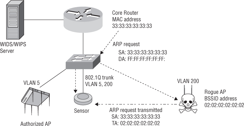
This will only work if the rogue device is plugged into the same broadcast domain as the sensor. Because many networks are designed with a large number of VLANs, a rogue AP could be plugged into a different VLAN than the sensors. As Figure 14.12 shows, the sensor would need to have an 802.1Q trunk link in order to receive the ARP request from the wired side.
FIGURE 14.12 Rogue detection—trunked sensor
All of these rogue detection and classification methods work well if the rogue device is indeed an access point. An access point is a Layer 2 device that bridges the 802.3 Ethernet interface and the 802.11 radio interface. Unfortunately, most rogue devices that are installed are low-cost home Wi-Fi routers and are not bridged devices. Therefore, most rogue devices have separate Layer 3 interfaces and are normally configured to use network address translation (NAT). As shown in Figure 14.13, one method of classifying Layer 3 rogue devices is to have a nearby sensor associate as a client station to the unauthorized suspect rogue AP or Wi-Fi router. The sensor then sends traffic, such as a ping, back to the WIDS/WIPS server. If the traffic reaches the server on the wired side, the suspected rogue AP is confirmed to be on the internal network and then classified as a rogue.
The problem with this method is that very often a rogue AP will have configured security, such as WEP or WPA. The sensor will not be able to associate with the rogue AP and send traffic because the sensor does not know the rogue APs security settings.
Luckily, the majority of the WLAN vendors that manufacture home Wi-Fi routers use MAC addresses that are one bit apart on the wireless and wired interfaces. As shown in Figure 14.14, the methods of Layer 2 rogue detection mentioned earlier can be augmented by looking for wired MAC addresses within a range of the BSSID detected by a sensor. A simple comparison of wireless and wired MAC is then used by the WIPS solution to classify the device as a rogue device.
FIGURE 14.13 Layer 3 Rogue detection—active sensor
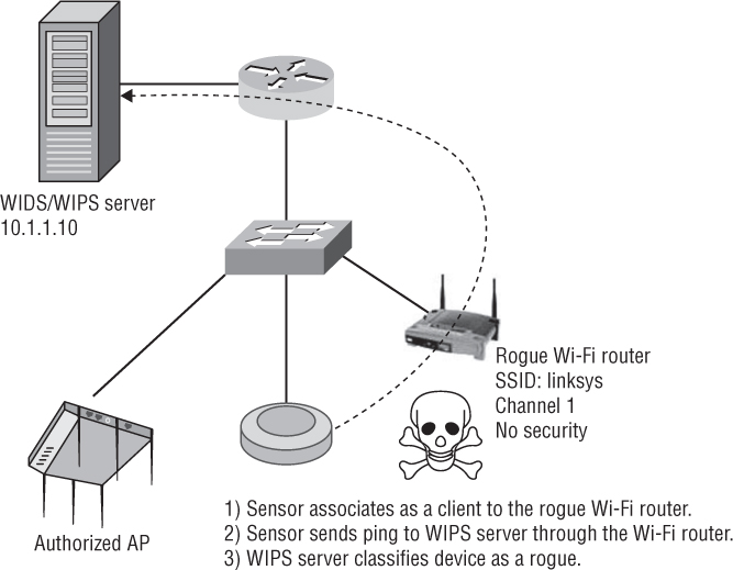
FIGURE 14.14 Layer 3 Rogue detection—MAC comparison

Another method for possibly determining whether there is a potential rogue device connected to the wired network is to examine the time to live (TTL) values of IP packets. Wi-Fi routers will lower the TTL value of a packet when it flows through the device. As mentioned earlier, WIDS/WIPS vendors may also use proprietary methods of rogue detection and classification. Some of these methods are proprietary published and some are not. One example is the use of a marker packet. The WIPs solution introduces a special marker packet on the wired side of the network. The marker packet is the transmitted into the wireless environment. If the WIPS solution detects any unauthorized BSSID transmitting the marker packet, the device is classified as rogue.
Although the art of rogue detection and classification has become quite successful, any device that is initially classified as unauthorized should also be investigated and treated as a potential rogue threat until determined otherwise. Once an unauthorized 802.11 device has been determined not to be a threat, the device can then be classified manually as a neighbor device.
Rogue Mitigation
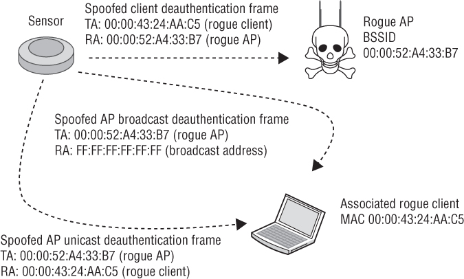
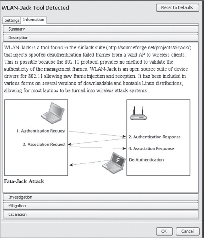
Once a client station or access point has been classified as a rogue device, the WIPS can effectively mitigate the attack. Every WIPS vendor has several ways of accomplishing this, but the most common method is wireless rogue containment using spoofed deauthentication frames. Rogue containment is accomplished wirelessly when the WIPS’s sensors become active and begin transmitting deauthentication frames that spoof the MAC addresses of the rogue access points, rogue ad hoc networks, and rogue clients. The WIPS is using a known Layer 2 denial-of-service attack as a countermeasure. The effect is that all communications between the rogue access point and clients are rendered useless. Any client devices trying to communicate through the rogue AP will be deauthenticated at Layer 2 and all upper-layer 3–7 communications will be disrupted. This prevents an attacker from accessing network resources through the unauthorized portal of the rogue AP. This also prevents accidental associations of legitimate clients to the rogue AP. This countermeasure can be used to disable rogue access points, individual client stations, and rogue ad hoc networks. Every WIPS vendor has its own marketing name for Layer 2 wireless rogue containment, including air termination, rogue blocking, and rogue disabling. As shown in Figure 14.15, the sensor transmits deauthentication frames spoofing the rogue APs MAC address as the transmitter address (TA). The receiver address (RA) of the spoofed frames may be a broadcast address to deauthenticate all client stations or may be a unicast address to a single, associated rogue client station. Hackers have figured out how to tinker with client radio firmware so that client stations will ignore deauthentication frames. Therefore, as shown in Figure 14.15, most WIPS sensors will also transmit deauthentication frames spoofing the client station’s MAC address as the transmitter address and spoofing the rogue AP MAC address as the receiver address.
FIGURE 14.15 Wireless rogue containment
Wireless rogue containment should be used very carefully. Rogue devices can be manually terminated using wireless rogue containment, or a WIPS can be configured to automatically terminate any devices that are classified as rogue. Many WIPS can also be configured to terminate all devices except for those that are classified as authorized. Using a deauthentication countermeasure against all unauthorized devices is not a good idea because the WIPS may accidentally terminate legitimate APs and clients from neighboring businesses. Improper use of wireless rogue containment capabilities can create legal problems. Any device that has been classified as rogue is a device that has been determined by the WIPS to be connected to the corporate backbone and probably should be wirelessly contained. It is up to your organization to choose whether wireless rogue containment is a manual procedure when rogue devices are discovered or whether legitimate rogue devices are automatically contained. Often for legal reasons, manual containment might be the wiser choice. Please understand that either manual or wireless rogue mitigation can only be used for a very short period of time. As soon as mitigation begins, the WLAN administrator should locate the rogue device and disconnect it from the wired network.
![]() Real World Scenario
Real World Scenario
In 2014 a major hotel chain operator admitted that employees improperly used a Wi-Fi monitoring system to block mobile hotspots. They also agreed to a three-year compliance plan with the FCC during which time they had to implement a compliance plan and report to the FCC every three months. As part of the agreement the hotel chain had to pay a civil penalty of $600,000 to resolve the Wi-Fi blocking investigation. The FCC Enforcement Bureau’s investigation determined that the hotel chain’s employees used the containment features of a WLAN monitoring system to prevent individuals from connecting to the Internet via their own personal Wi-Fi networks, while at the same time charging consumers and exhibitors as much as $1,000 per device to access the hotel’s Wi-Fi network. The complaint alleged that the hotel was jamming mobile hotspots to prevent their use within the hotel’s grounds. More information about this incident can be found at www.fcc.gov/document/marriott-pay-600k-resolve-wifi-blocking-investigation.
As mentioned earlier in this chapter, using APs for rogue containment is not a recommended practice. If a time slicing AP/sensor must go off-channel for an extended period of time to contain a rogue device, the AP is not on its home channel providing access to clients. If the AP is performing rogue containment instead of providing access, the performance of the WLAN can be affected. Most WLAN vendors have a configuration setting that prevents a time slicing AP/sensor from performing rogue termination when clients are associated. If clients are associated to all the APs, then rogue containment may not occur when needed. Although the access points act as part-time sensors for the integrated IDS server, it is a highly recommended practice also to deploy some APs as full-time sensors when using an integrated WIDS/WIPS server solution. The full-time sensors would be used for rogue containment instead of the time slicing AP/sensors.
As mentioned in Chapter 12, “Wireless Security Risks,” ad hoc WLANs are a huge security risk because the Ethernet connection and the Wi-Fi radio can be bridged together. An intruder might also access the ad hoc WLAN and then potentially route their way to the Ethernet connection and get onto the wired network. A WIPS solution can easily detect an ad hoc WLAN because ad hoc stations transmit 802.11 Beacon frames that indicate they are participating in an independent basic service set (IBSS). As shown in Figure 14.16, after detecting the ad hoc stations, a WIPS can send spoofed deauthentication frames to disrupt communications within the IBSS. Temporary wireless termination of ad hoc WLANs may also be required.
FIGURE 14.16 Ad hoc containment

Many WIPS also use a wired-side termination process to effectively mitigate rogue devices. The wired-side termination method of rogue mitigation uses the Simple Network Management Protocol (SNMP) for port suppression. Most WIPS can determine that the rogue access point is connected to the wired infrastructure and may be able to use SNMP to disable the managed switch port that is connected to the rogue access point. Port suppression uses an SNMP agent to shut down the physical port on the network switch through which a rogue device is communicating. If the physical port on the switch is disabled, the gateway to wired network is effectively closed and an attacker cannot use the rogue AP to access network resources.
WIPS vendors have other proprietary methods of disabling rogue access points and client stations and often their methods are not published. Currently, the main attack mitigated by a WIPS is an attack by rogue devices. In the future, other wireless attacks might be mitigated as well.
Device Tracking
Once a device has been detected and classified, the internal monitoring capabilities of a WIDS/WIPS server can be used to locate the device. As shown in Figure 14.17, the location of devices can be shown visually onto a graphic image of the building’s floor plan that has been imported into the WIDS/WIPS server. Location tracking is often used to pinpoint the location of rogue APs, but location tracking can also be used to establish the vicinity of authorized APs and client stations.
FIGURE 14.17 Location tracking
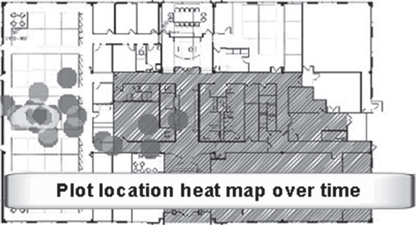
The method used to find devices will vary based on vendor implementation and optional configurations. Some methods of location tracking use received signal strength indicator (RSSI) values reported from sensors and authorized APs within listening range of the device being tracked. Newer features also include historical location tracking. As you can see in Figure 14.18, historical tracking allows the WIDS/WIPS to show where a device has been detected in the past, even if the device is not currently transmitting. Historical tracking capabilities are used to monitor the movements of rogue client stations. Historical tracking also provides data that can be used to find missing devices, such as handheld scanners that may have become misplaced in a retail, warehousing, or logistics environment. Furthermore, the historical data can also be used to find trends in worker movement throughout the day as required by their jobs. Whether the device you have detected is rogue, authorized, or just neighboring, it eventually becomes necessary to know the physical location of a device.
FIGURE 14.18 Historical tracking
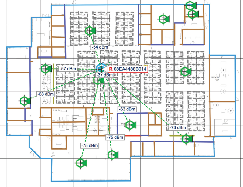
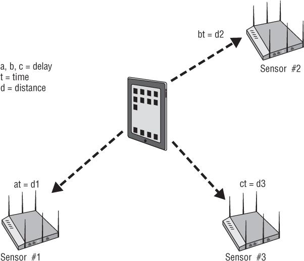
The most common location tracking method is known as RF triangulation. Triangulation, as it relates to WIDS/WIPS, is a way of using received signals detected by sensors that are in known locations to find devices that are in unknown locations. Within the WIDS/WIPS tracking module, sensors are positioned on a map of the area where the sensors are actually deployed. Each sensor reporting that it hears the target device provides a data point for use in finding the target based on the RSSI value of the target’s signal. Sensors that detect the target with stronger signal strength (a higher RSSI value) are believed to be closer to the target. Those sensors detecting the target with weaker signal strength (a lower RSSI value) are determined to be farther away from the target. Because RSSI provides an estimate of distance but not direction, at least three sensors are needed to determine the location of a monitored device. As shown in Figure 14.19, RF triangulation provides an approximation of the target’s location based solely on the varied RSSI values detected and reported by multiple sensors.

RF triangulation usually results in an estimated location within approximately 10 meters. However, this method does not take into account the RF noise in the area, nor does it account for the attenuation, reflection, absorption, scattering, or multipath that may be occurring as the target’s signal propagates throughout the area. The antenna orientation of a mobile client station will also affect the RSSI measurement. The accuracy of RSSI measurement is affected by distance as well. The doubling of the distance between a sensor and a device tends to double the inaccuracy of the measurement. Therefore, RF triangulation is usually used as an approximation. In most cases, an approximation of 10 meters is accurate enough to locate a device physically.
![]() Real World Scenario
Real World Scenario
In the past, some vendors used proprietary software mechanisms on client stations to measure RSSI from access points continuously and to report this measurement back to a location tracking module of a WIDS/WIPS server. Because more statistical data is collected from the clients and not just APs or sensors, the accuracy of tracking authorized clients is enhanced. The ratified 802.11k-2008 amendment defines standards for radio resource measurement (RRM). WLAN radio resource measurements enable STAs to understand the radio environment in which they exist by measuring RSSI, signal noise, and other statistics. Radio measurement data can be made available to upper protocol layers, where it may be used by other applications, including location tracking services of a WIPS. One optional measurement defined by 802.11k is location configuration information (LCI), which can be used by an 802.11 client device that might also have GPS capabilities. LCI measurements can be used to report latitude, longitude, and altitude. Although 802.11k mechanisms still have the potential to improve location tracking accuracy of Wi-Fi clients, support for LCI mechanisms on Wi-Fi clients has yet to happen. In reality, triangulation or trilateration will never be as accurate as real-time location-tracking systems. At best, the estimated locations may become more accurate but they cannot compare to an active RFID tag on the device being tracked that helps you find it.
A more complex yet more accurate method of device location tracking is RF fingerprinting. RF fingerprinting also uses the RSSI values of transmitting devices as detected by sensors. However, RF fingerprinting does not rely on these values alone. RF fingerprinting also uses the RSSI values of devices whose locations are known as points of comparison. Rather than just listening to the target device’s signal and estimating the target’s location, this method compares the target’s detected RSSI values with the RSSI values of the known reference points. The idea here is that if the target and the known reference point have similar RSSI values, they must be close to each other. RF fingerprinting relies on building up a database of actual measurements and relates them to particular locations. This method can reduce the size of the search pattern from 10 meters down to about 1 or 2 meters and may be deployed using fewer sensors. However, RF fingerprinting can also be time-consuming and expensive.
The method used to document RSSI reference points on a map is known as RF calibration. The calibration is often done by an administrator using an 802.11 device (usually a laptop) moving throughout the area and taking many samples of RSSI data to be imported into the RF fingerprinting engine. If anything in the area changes the RF environment—such as new walls, neighboring devices, new interference sources, or the removal of these things—the RF fingerprinting will not function correctly until the engine can be recalibrated to include these changes in the RF environment. Recalibration is often overlooked by WLAN administrators who are busy with other tasks. The result of using a poorly calibrated RF Fingerprinting engine to track devices may be less accurate than just using RSSI values and RF triangulation. Although the RF fingerprinting method is more accurate than triangulation alone, it is more costly to implement and more labor intensive to maintain. The 8 or 9 meter accuracy improvement that RF fingerprinting provides is useful for locating rogue APs and for tracking Wi-Fi RFID tags. Several companies such as AeroScout and Ekahau provide WLAN real-time location systems (RTLSs) that use RF fingerprinting methods. Several of the WLAN vendors and WIDS/WIPS vendors partner with RTLS vendors to take advantage of the increased accuracy provided by RF fingerprinting.
Time difference of arrival (TDoA) is another method that can be used for location tracking. As shown in Figure 14.20, TDoA uses the variation of arrival times of the same transmitted signal at three or more receivers—in our case, sensors. The transmitted signal will arrive at the sensors at different times due to the distance between the transmitter and the multiple sensors. The speed of travel of the radio frequency is a known factor, and each of the synchronized TDoA sensors reports the time of arrival of the signal from the transmitting device. In theory, if the transmitter were exactly at the midpoint between sensors, there would be no difference of arrival times, thus making the target easily located in the center of sensor coverage, equally distanced from all sensors. Ordinarily, the sensor that receives the signal first is deemed closer to the source of the transmission and the one receiving the signal last should be the farthest away from the source. The TDoA is also used in determining the angle of arrival (AoA) of a signal in an antenna array. TDoA does not require the calibration of RF fingerprinting, nor does it use the RSSI values as triangulation methods. TDoA simply uses the time stamps of the signal’s arrival at various known locations. Some WLAN vendors are using TDoA technology to assist in tracking Wi-Fi RFID tags. Wi-Fi TDoA sensors are typically used for location tracking in line-of-sight environments, such as outdoor deployments or warehouses with high ceilings.
FIGURE 14.20 Time difference of arrival (TDoA)
It is possible to conduct device tracking with a single mobile receiver taking multiple readings in several locations by hand using a laptop or handheld device. However, the speed at which distributed systems are able to accomplish this same task makes location tracking an important and reliable part of WLAN security monitoring. Using a single mobile device to supplement location tracking is a good practice for “last mile” discovery. As shown in Figure 14.21, mobile devices usually use a graph, needle, and/or sound to indicate proximity to the target device. Using the WIDS/WIPS to approximate the location and then following through by using the portable device is a common method of locating rogues and other devices in a WLAN enterprise. No matter which method you choose, you will most likely encounter a situation that requires finding the physical location of a device.
FIGURE 14.21 Mobile tracking tool

WIDS/WIPS Analysis
As you have learned, WLAN security monitoring using a distributed WIDS/WIPS solution is capable of collecting information continuously. Because the information gathered from multiple sensors can be extensive, the task of analyzing all the collected data can be overwhelming. Every WIDS/WIPS solution uses a variety of software modules or software engines to simplify the task of analyzing massive amounts of collected data.
Signature Analysis
WIDS/WIPS solutions use signature analysis to analyze frame patterns or “signatures” of known wireless intrusions and WLAN attacks. The WIDS/WIPS has a programmed database of hundreds of threat signatures of known WLAN attacks. As shown in Figure 14.22, threat signatures can include man-in-the-middle attacks, DoS attacks, flood attacks, and many more. WIDS/WIPS signatures are based on Layer 1 and Layer 2 attacks. The WIDS/WIPS uses some sort of signature analysis engine that processes 802.11 frames and RF data. Automatic signature learning systems require extensive logging of complex network activity and historic data mining that can impact performance. Most WIDS/WIPS solutions use manual signature detection, which is comparable to most virus protection systems, where the signature database is updated automatically as new signatures are discovered. WIDS/WIPS vendors are constantly updating their signature databases as new attacks emerge. Usually, the systems also have the capability of creating custom signatures. Custom signatures are useful to WLAN administrators who want to monitor for a behavior or attack that could be specific to their WLAN environment.
FIGURE 14.22 Attack signatures

Behavioral Analysis
Many WIDS/WIPS solutions also use behavioral analysis to recognize any patterns that deviate from normal WLAN activity. Behavioral analysis identifies abnormal network behavior based on historical metrics. Because historical normal WLAN behavior is the baseline, anomalies can be detected that would not necessarily be discovered by other intrusion detection techniques. Whereas the signature analysis identifies known threats, the anomalous behavior analysis recognizes new, unknown attacks or threats that have no signature.
Detection of anomalies can be based on various thresholds of 802.11 management, control and data frames, fragmentation thresholds, and many other variables. Behavior analysis helps detect protocol fuzzing, where an attacker sends malformed input to look for bugs and programming flaws in AP code or client station firmware. Attackers transmit malformed data by tampering with bits and fields of data in 802.11 frames. Protocol fuzzing attacks often identify driver vulnerabilities and find weaknesses that result in a buffer overflow attack.
As you have learned, known attacks can be easily identified by signature analysis. However, the greatest threat to WLAN security is a new attack that is not known and cannot be detected. An unknown threat used to exploit computer networks is referred to as a zero day attack. Very often, a zero day attack will create some sort of anomaly in 802.11 behavior that can be detected. As shown in Figure 14.23, behavior thresholds can be configured on the WIDS/WIPS that can trigger an alarm. When setting thresholds, you may find it difficult and time-consuming to achieve a balance in detecting possible zero day attacks versus triggering false positive alarms.
FIGURE 14.23 Behavior thresholds
Protocol Analysis
All WIDS/WIPS vendors use protocol analysis to dissect the MAC layer information from 802.11 frames. Protocol analysis may also be used to analyze Layer 3–7 information of 802.11 data frames that are not encrypted. In Chapter 13, “Wireless LAN Security Auditing,” you learned that standalone WLAN protocol analyzers are usually installed on a laptop and are used for security audits. Standalone WLAN protocol analyzers are also used for Layer 2 troubleshooting and WLAN performance analysis. The Wireshark software you have been using in the book’s exercises is a standalone WLAN protocol analyzer. All standalone WLAN protocol analyzers have some security analysis capabilities, but some place a greater emphasis on security auditing and can effectively be used as a mobile wireless intrusion detection system solution. One example is Fluke Networks’ AirMagnet Wi-Fi Analyzer. Although this approach is rarely used, mobile WIDS analyzers can also be integrated with a distributed WIDS/WIPS, effectively acting as software-based sensors.
An enterprise WIDS/WIPS solution provides for distributed protocol analysis, with each hardware sensor acting as a listening device. Distributed protocol analysis is mainly used to monitor all the 802.11 frame exchanges that occur at Layer 2. That information can be leveraged for both security reasons and for WLAN performance analysis. Attacks can be detected at Layer 2 by reading the headers and trailers of all of the frames captured with a distributed protocol analyzer.
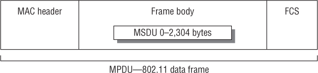
An in-depth discussion of 802.11 protocol analysis is beyond the scope of this book; however, a quick discussion of the 802.11 frame format is necessary. The technical name for an 802.11 data frame is a MAC Protocol Data Unit (MPDU). The 802.11 frame, as shown in Figure 14.24, contains a Layer 2 MAC header, a frame body, and a trailer, which is a 32-bit CRC known as the frame check sequence (FCS). The Layer 2 header contains MAC addresses and the duration value. The frame body contains the MAC Service Data Unit (MSDU), which is the Layer 3–7 payload.
FIGURE 14.24 MAC Protocol Data Unit
The IEEE 802.11-2012 standard defines three major frame types:
Management 802.11 management frames are used by wireless stations to join and leave the basic service set (BSS). Another name for an 802.11 management frame is a Management MAC Protocol Data Unit (MMPDU). Management frames do not carry any upper-layer information. There is no MSDU encapsulated in the MMPDU frame body, which carries only Layer 2 information fields and information elements. Information fields are fixed-length mandatory fields in the body of a management frame. Information elements are variable in length and are optional. Examples of management frames are beacons, probe requests, and association request frames.
Control 802.11 control frames assist with the delivery of the data frames. Control frames must be able to be heard by all stations; therefore, they must be transmitted at one of the basic rates. Control frames are also used to clear the channel, acquire the channel, and provide unicast frame acknowledgments. They contain only header information. Control frames do not have a frame body. Examples of control frames are acknowledgments, request-to-send, and clear-to-send frames.
Data Most 802.11 data frames carry the actual data that is passed down from the higher-layer protocols. The Layer 3–7 MSDU payload is normally encrypted for data privacy reasons.
Most WIDS/WIPS have the capability to monitor 802.11 frame exchanges in real time just like a standalone WLAN protocol analyzer. Enterprise WIDS/WIPS also usually have the ability to use sensors and APs for remote packet capture. As shown in Figure 14.25, an individual sensor is configured to capture on a single channel and then mirror the captured 802.11 traffic to a remote IP address.
FIGURE 14.25 Remote packet capture

Spectrum Analysis
Always remember that 802.11 devices operate at both Layers 1 and 2. The Layer 1 physical medium is the uncontrolled, unlicensed, and unbounded RF spectrum. Traditionally, WIDS/WIPS solutions have mostly been used strictly to monitor Layer 2 communications and have mostly ignored Layer 1 for security monitoring. As you learned in Chapter 12, DoS attacks can occur at Layer 1. Any continuous transmitter will cause a DoS. RF jamming devices can be used by an attacker to cause an intentional Layer 1 DoS attack. Denial of service at Layer 1 usually occurs as an unintentional result of transmissions from non-802.11 devices. Video cameras, baby monitors, cordless phones, and microwave ovens are all potential sources of interference. Unintentional interference may cause a continuous DoS, but the disruption of service is often sporadic. This disruption of service will upset the performance of Wi-Fi networks used for data applications but can completely disrupt VoWiFi communications within a WLAN. At the very least, unintentional interference will result in retransmissions that negatively affect WLAN performance. The majority of unintentional interfering devices transmit in the 2.4 GHz ISM frequency band. The 5 GHz UNII bands are less susceptible to unintentional interference. RF interference often is undetected by traditional WIDS/WIPS sensors and cannot be properly classified.
Although wireless intrusion prevention systems are outstanding products that can mitigate most rogue attacks, some rogue devices will go undetected. The radios inside the WIPS sensors typically monitor the 2.4 GHz ISM band and the 5 GHz UNII frequencies. Older legacy wireless networking equipment exists that transmits in the 900 MHz ISM band, and these devices will not be detected. The radios inside the WIPS sensors use only direct sequencing spread spectrum (DSSS) and orthogonal frequency division multiplexing (OFDM) technologies. Wireless networking equipment exists that uses frequency hopping spread spectrum (FHSS) transmissions in the 2.4 GHz ISM band and will go undetected by traditional WIDS/WIPS sensors. The only tool that will detect with 100-percent certainty either a 900 MHz or a frequency hopping rogue access point is a spectrum analyzer capable of operating in those frequencies.
A spectrum analyzer is a frequency domain measurement and troubleshooting tool. A spectrum analyzer can help identify and locate an interfering transmitter. Spectrum analyzer hardware can cost upward of $40,000, thereby making them cost-prohibitive for many small and medium-sized businesses. The good news is that several companies have standalone solutions, both hardware and software based, that are designed specifically for 802.11 spectrum analysis and are drastically less expensive. As shown in Figure 14.26, WLAN spectrum analysis is most often achieved with a standalone software-based solution installed on a laptop that works with special USB adapters that use a spectrum analyzer chipset.
FIGURE 14.26 WLAN spectrum analyzer

One of the most important capabilities of a spectrum analyzer is the ability not only to detect RF energy but also to classify the sources of the interference. The better spectrum analyzers use RF signature analysis to identify and classify interfering RF transmitters, such as Bluetooth, microwave ovens, wireless cameras, jammers, and so on.
In the past, a major oversight in many WIDS/WIPS solutions was that they were unable to detect previously discussed Layer 1 security threats. However, in recent years, enterprise WIPS have begun to operate as distributed spectrum analysis systems (DSASs). The advantage of any distributed solution is that they run 24/7 and can be administered remotely. Most DSAS solutions use access points for the distributed spectrum analysis. Some vendor APs use an integrated spectrum analyzer that operates independently from the 802.11 radio. Other vendor APs use the 802.11 radio to accomplish a lower grade of spectrum analysis. A good DSAS is capable of RF signature analysis and can also physically pinpoint sources of RF interference using the location-tracking capabilities discussed earlier in this chapter.
Forensic Analysis
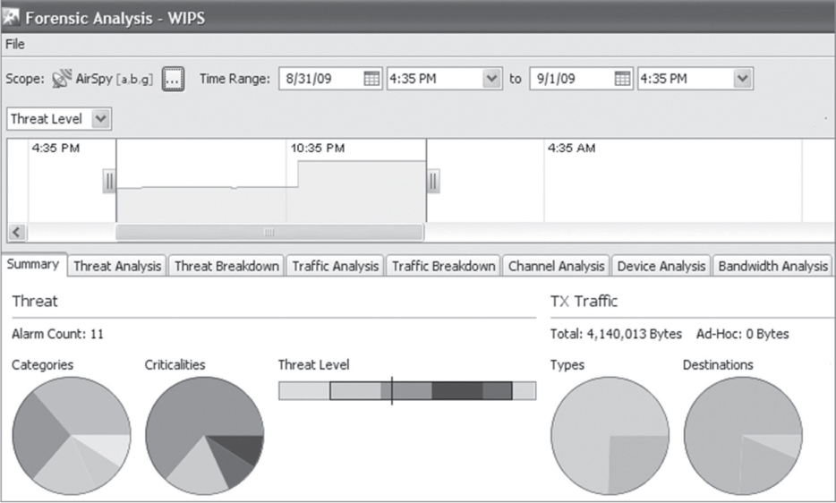
Enterprise WIDS/WIPS solutions may also provide forensic analysis that allows an administrator to retrace the actions of any single WLAN device down to the minute.
With forensic analysis, investigating an event takes minutes instead of potentially hours. Administrators can rewind and review minute-by-minute records of connectivity and communication within a WLAN. As shown in Figure 14.27, the WIPS records and stores hundreds of data points per WLAN device, per connection, per minute. This allows an organization to view months of historical data on any suspicious WLAN device as well as all authorized devices. Information such as channel activity, signal characteristics, device activity, and traffic flow and attacks can all be viewed historically.
FIGURE 14.27 Forensic analysis
Performance Analysis
A very useful by-product of WIDS/WIPS deployment is that you are able to collect a large amount of data for analysis for performance monitoring. Although the main purpose of an enterprise WIDS/WIPS is security monitoring, information collected by the WIPS can also be used for performance analysis. Since everything WLAN devices transmit is visible to the sensors, the Layer 2 information gathered can be used to determine the performance level of a WLAN. The WIPS can detect hidden nodes, excessive Layer 2 retransmissions, excessive wired to wireless traffic, excessive roaming, and many other events and traffic types that lower the capacity performance of a WLAN.
Knowing how the WLAN functions on a regular basis can help reduce problem-solving time greatly. Performance analysis can be used to define performance baselines used to establish expected performance standards or levels. Baselining involves determining how the WLAN is functioning in terms of performance. An administrator must take several samples of traffic at various times. These samples should be taken at both peak and off-peak times and over a long enough period to capture adequately an idea of what is normal for the WLAN. The baseline should include normal use conditions as well as peak and off-peak captures. Using captures from longer periods will allow you to better understand normal use of the network and have a more accurate baseline. Since the WIDS/WIPS is collecting information all day, every day, the sampling for a baseline is more accurate and more inclusive. Once a baseline has been established for the WIDS/WIPS, performance thresholds can be configured to send alerts when performance drops to detrimental levels. Performance monitoring allows an administrator to act on potential network issues before the users notice any performance problems. Performance monitoring also aids in the planning for any necessary expansion of the WLAN. If an administrator knows how well the WLAN functions with the current number of APs and stations running the current applications, the impact of adding more users and devices can be more accurately predicted.
Monitoring
With the vast amount of data that can be collected, it is of great importance to have the WIDS/WIPS properly tuned for your environment. Alarm policies can be configured to define thresholds for security and performance. Custom alarm threat thresholds can be configured to match the WLAN’s security and performance requirements. Alarm notifications can also be triggered to alert you about attacks. You can then evaluate the alarms and take the proper actions.
Policy Enforcement
Enterprise WIDS/WIPS solutions allow administrators to define, monitor, and enforce wireless LAN policies in the areas of security, performance, usage, and vendor types. Organizations can minimize vulnerability by ensuring that WLAN devices are using the proper security protocols. Improper configuration of WLAN devices is one of the most common causes for wireless security breaches.
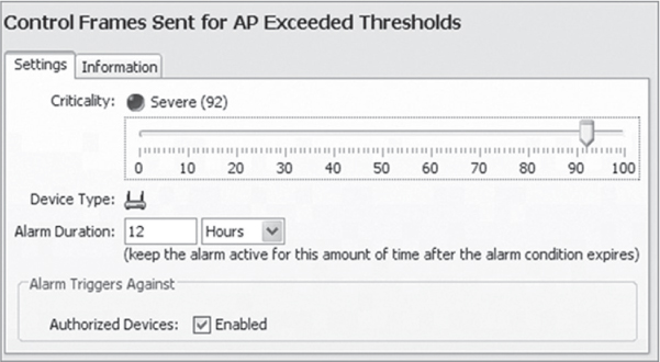
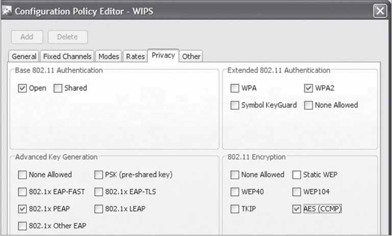
Security policies must be defined to set thresholds for acceptable network operations and performance. As shown in Figure 14.28, you can define a security policy that requires that all client stations use an 802.1X/PEAP solution for authentication and CCMP/AES for encryption. If an end user configures a client station that is not using PEAP and CCMP, the WIPS will generate a policy-based alarm. Defining security policies ensures that all devices are properly configured with the mandated level of protection.
Security policies need to be set for both access point and client station configuration thresholds. Policies should be defined for authorized APs and their respective configuration parameters, such as Vendor ID, authentication modes, and allowed encryption modes. Define allowable channels of operation and normal activity hours of operation for each AP. Performance thresholds can also be defined for minimum signal strength from a client station associating with an AP to identify potential attacks from outside the building.
The defined security policies form the baseline for how the WLAN should operate. The thresholds and configuration parameters should be adjusted over time to tighten or loosen the security baseline to meet real-world requirements. For example, normal activity hours for a particular AP could be scaled back due to working hour changes. The security policy should also be changed to reflect the new hours of operation. No one security policy fits all environments or situations. There are always trade-offs between security and usability.
The WIPS can also be used for policy enforcement. Once again, you can define a security policy that requires all client stations use an 802.1X/PEAP solution for authentication and CCMP/AES for encryption. If an end user configures a client station that is not using PEAP and CCMP, the WIPS will generate a policy-based alarm. However, the security policy can also be set to trigger an automatic response in addition to the alarm. The WIPS can use spoofed deauthentication frames against the misconfigured client, similar to rogue containment measures. In this way, authorized devices are not able to place their traffic at risk by communicating without the use of required authentication or encryption methods. A policy is only as good as its ability to be enforced uniformly. An alarm will alert you to an unsecure environment or device but does not take steps to enforce the policy. A WIPS offers the additional protection of preventing devices from communicating outside of policy by terminating noncompliant devices connections. This approach does have the potential to disrupt business and should be properly weighed against potential security problems when making the decision to terminate noncompliant connections. Many users of WIPS in larger enterprise deployments with 24/7 staffing prefer to receive notifications of noncompliant device communications and manually remediate the problem to avoid business interruption.
NOTE
Prior to implementing actions to enforce policy, it is of great importance that any written organizational security policy be consulted, followed, and or updated and required. Policy violation reporting and policy enforcement may be dictated by outside organizations based on industry and governmental regulations. You can find a more detailed discussion about policies and regulations in Chapter 15, “Wireless Security Policies.”
Alarms and Notification
In a congested WLAN environment or in an area with very little traffic, any 802.11-based device that transmits a signal can be heard by the WIDS/WIPS sensors. The WIDS/WIPS will detect all 802.11 transmissions and then, if necessary, generate the appropriate alarms. Depending on the configured threshold, the alarms can be triggered by signature analysis, spectrum analysis, behavioral analysis, or performance analysis. Alarms can also be policy based, as we discussed in the previous section. Practical questions then arise once the alarms have been triggered:
What do I do with all of this information?
What do these alarms mean?
Do I need to be informed about every device detected?
Who is going to respond to the alarms?
Am I under attack?
Is this normal or acceptable behavior?
Are any or all of these detected devices mine?
Are my devices safe?
As shown in Figure 14.29, the triggered alarms will often have a detailed description of the attack or performance problem. The WIPS alarm may also have suggested mitigation actions. The detailed description and recommended actions will often help you answer the questions we just listed.
As we discussed earlier, WIDS and WIPS solutions are able to discover and classify devices as well as conduct behavioral analysis. Event alerts or alarms are used to indicate that a device or particular behavior has been detected by the system. Different behaviors will trigger different alarms. If a user turns on a new client device within hearing range of a sensor, an unauthorized device alarm will be triggered. If that user then connects to an authorized AP without their new client device first being authorized, a rogue station alarm will be triggered. What happens beyond that depends on the vendor of the WIDS/WIPS and the customization done to the system. A WIPS can proactively begin to protect the network using rogue station containment.
Users, contractors, and visitors often have the credentials to connect and do so using their own devices. This will trigger alarms within the WIDS/WIPS based on the classification of their device as unauthorized and the behavior analysis of the device showing it as associated with an authorized AP. Any device detected and any behavior detected can be used to trigger alarms and possible automatic responses.
Alerts or alarms can be classified just as devices can be classified. Events that trigger alarms are not always indications of security threats or vulnerabilities. Some events are normal behavior, such as protection mode in use by an 802.11g access point or including its SSID in the beacon frames it transmits. The alarms can be broken into several categories:
Behavioral
Exploits
Performance
Policy compliance
Reconnaissance
Rogue activity
Performance
Vulnerabilities
WIDS/WIPS alarms are usually set to a threat-criticality level the vendor has determined to be what most users want. However, you may wish to make some alarms more or less important than the preset threat levels. Within the categories, alarms or alerts can be given custom threat levels from “everything is fine” to “we are under attack.” These levels include the following:
Safe No immediate threat
Minor Potential problem alarms that may worsen if ignored
Major Potentially serious alarms that require priority attention
Critical Serious alarms that require immediate attention
Severe Serious alarms that may have catastrophic effects
Tuning the alerts or alarms to threat levels is an important and possibly time-consuming task when deploying a WIDS/WIPS. However, spending the time up front to calibrate alarm thresholds properly will make the alerts more meaningful. The intended use of a WIDS/WIPS along with vendor-specific options will dictate how you should tune the alarm thresholds. Alarms can be disabled or have their threat levels lowered if they are not of importance.
Keeping a record of everything that is detected is a sound practice for forensic or even legal reasons. However, you may not want to receive a notification about everything the system detects. An alarm can be configured to trigger notifications, which can be sent from the system in several forms:
Email
SMS
Syslog
The notifications should be configured to trigger only if an alarm is of specific importance to you. You would want to be alerted to the fact that a rogue is on the network or an attack is occurring. However, you would not want to know every time a WLAN device is detected unless a no-wireless zone is being enforced. Typically, alarms with a threat level of critical or severe are also configured for notification. It should be noted that any AP or client that is initially classified as unauthorized should still be investigated as soon as time permits.
False Positives
The physical radio frequency medium used for 802.11 communications is both harsh and unpredictable. RF behaviors, such as reflections and multipath, often create a hostile environment that results in corrupted 802.11 frames and Layer 2 retransmissions. WLAN problems, such as adjacent cell interference, low SNR, and hidden nodes, can also lead to corrupted data frames. Because the RF environment is at worst unstable and at best fluctuating, not every WIDS/WIPS alarm is going to be perfectly accurate. In other words, a certain number of false positive alarms are to be expected. A false positive, also known as a false detection or false alarm, is a result that is erroneously positive when the situation is actually normal. A false positive is simply another way of saying “mistake.” All intrusion detection systems, both wired and wireless, will have some occurrence of false positives. A false positive WIDS/WIPS alarm indicates that a WLAN attack is occurring when in fact the threat does not exist. False positive alarms can be time consuming for you to verify or invalidate. Even worse, false positives are often ignored due to their volume, thus increasing the possibility that a real attack alarm will also be ignored.
Corrupted frames are the leading cause of false positives. However, improper configuration of the WIPS or misinterpretation of alarms by administrators can also lead to false positive alarms. Proper classification of all devices as either authorized devices or neighbor devices is important. If devices are not properly classified, many alarms will be triggered. As mentioned earlier in this chapter, setting alarm thresholds can often be difficult and it may be time consuming to achieve a balance in detecting possible attacks versus triggering false positive alarms. Some inaccurate reporting of events, seen as false positives, are unavoidable. However, properly setting alarm thresholds that are fine-tuned to the on-site RF environment can greatly reduce the number of false positives. A reduction in false positives will save time and improve the security of the WLAN.
Reports
Enterprise WIDS/WIPS solutions usually offer extensive report generation capabilities. Reports can be created manually or can be scheduled to be created automatically. Viewing and saving these reports is part of maintaining a secure and healthy wireless environment. When properly created, reports are useful tools in problem analysis and resolution. Security issues that may require disciplinary and or legal action are better supported with documentation. The reports can also be used to validate expenditure issues with upper management with regard to network security and development requirements.
The report software engine of the WIDS/WIPS will have many predefined reports that cover compliance, security, and performance. Additionally, the WIPS administrator will usually have the option to create custom reports that address the individual needs of a specific WLAN that is being monitored.
NOTE
Examples of two WIPS-generated reports are available for download from the book’s website: www.sybex.com/go/cwsp2e. The reports are titled Security_Rogue_Detail_report.pdf and Vulnerability_Assessment_Report.pdf.
802.11n/ac
The 802.11n-2009 amendment introduced the use of High Throughput (HT) radios that use both PHY and MAC layer enhancements to achieve these high data rates. The amendment introduced the use of multiple-input and multiple-output (MIMO) radios that use both PHY and MAC layer enhancements to achieve much higher data rates than legacy 802.11a/b/g single-input and single-output (SISO) radios. The 802.11ac Very High Throughput (VHT) amendment tweaked and defined more PHY and MAC enhancements so that 5 GHz MIMO radios could achieve even higher data rates than 802.11n radios. Does a WLAN administrator need to update WIPS sensors to use MIMO radios as well? The answer depends on the level of protection and monitoring that is required.
The biggest concern is always rogue access points. The good news is that rogue 802.11n and rogue 802.11ac APs will still transmit beacons at data rates that can be decoded by legacy 802.11a/b/g WIPS sensors. This means that most rogue detection methods should still work. However, 802.11n introduced an HT Greenfield mode that uses a PHY header that only 802.11n radios can understand. A legacy 802.11a/b/g sensor will not be able to decipher any transmissions using the HT Greenfield frame format. An attacker could potentially install a rogue 802.11n AP that is only transmitting using the HT Greenfield frame format. The HT Greenfield PHY header cannot be detected by a WIPS that is using legacy 802.11a/g sensors. HT Greenfield mode was never really used in the enterprise and has been dropped in 802.11ac.
802.11n HT radios also have the ability to transmit on 40 MHz OFDM channels. As shown in Figure 14.30, the 40 MHz channels used by HT radios are essentially two 20 MHz OFDM channels that are bonded together. Each 40 MHz channel consists of a primary and a secondary 20 MHz channel. 802.11ac VHT radios have the ability to transmit on 20 MHz, 40 MHz, and 80 MHz channels. The good news is that the majority of 802.11 management frames, such as beacons, are transmitted on the primary 20 MHz channel so that legacy 802.11a/b/g radios can also communicate with 802.11n/ac radios. However, the legacy radios will not be able to understand 40 MHz or 80 MHz transmissions. Any Layer 2 denial-of-service (DoS) attacks on the larger channels would go undetected by the older SISO radios. As new technologies are introduced, new attacks always follow. In an ideal world, your WIPS sensors should be updated when newer 802.11 radio technologies are introduced.

802.11w
The IEEE ratified the 802.11w-2009 amendment defines management frame protection for the prevention of Layer 2 DoS attacks.
Disassociation frames can be sent by either an AP or a client station. Disassociation is a notification, not a request. In the past, disassociation could not be refused by the receiving station. 802.11w allows the receiving STA to refuse disassociation when management frame protection (MFP) is negotiated and the message integrity check fails. Deauthentication frames can also be sent by either an AP or a client station, and deauthentication is a notification, not a request. In the past, deauthentication could not be refused by the receiving station. 802.11w allows the receiving STA to refuse deauthentication when management frame protection is negotiated and the message integrity check fails.
The 802.11w-2009 amendment defines a robust management frame as a management frame that can be protected by the management frame protection service. The robust management frames include robust action frames, disassociation frames, and deauthentication frames. The majority of action frames are considered robust, including QoS action frames, radio measurement action frames, block ACKs, and many more.
As you learned in Chapter 3, “Encryption Ciphers and Methods,” TKIP/RC4 and CCMP/AES provide protection against replay attacks against 802.11 data frames. However, only CCMP/AES is supported for protection of robust management frames. Replay protection is provided for robust management frames for STAs that use CCMP and Broadcast/Multicast Integrity Protocol (BIP). BIP provides message integrity and access control for group-addressed robust management frames. 802.11w should help put an end to deauthentication attacks and disassociation attacks as well as Layer 2 DoS attacks that involve action frames. Although 802.11w does address these two popular DoS attacks, 802.11w will not address many other Layer 2 DoS attacks.
Numerous Layer 2 DoS attacks exist, including association floods, EAPOL floods, PS-Poll floods, and virtual carrier attacks. 802.11w does not address these types of Layer 2 DoS attacks. Luckily, any good wireless intrusion detection system will be able to alert an administrator immediately to a Layer 2 DoS attack. Please understand that 802.11w compliance will eventually prevent some of the popular Layer 2 DoS attacks that currently exist, but it is doubtful that all Layer 2 DoS attacks will ever be circumvented.
As of this writing, there currently is very little support for 802.11w management frame protection in 802.11 clients. Most of the WLAN vendors support 802.11w mechanisms in their APs, but client-side support is still scarce.
![]() Real World Scenario
Real World Scenario
As you know, most WIPS solutions use a wireless rogue containment that uses spoofed deauthentication frames. Rogue containment is accomplished wirelessly when the WIPS’s sensors become active and begin transmitting deauthentication frames that spoof the MAC addresses of the rogue access points, rogue ad hoc networks, and rogue clients. The WIPS is using a known Layer 2 DoS attack as a countermeasure. 802.11w defines mechanisms that protect deauthentication frames. Therefore, wireless rogue containment based on management frames protected by 802.11w will not work against 802.11w rogue devices. As 802.11w-compliant devices become more widely available, WIPS vendors will have to rely on other methods for rogue mitigation and prevention. Port suppression will become a more important method of rogue AP deterrence. Additionally, use of 802.1X/EAP for switch port security is becoming more important for rogue AP prevention.
Other WIPS vendors may rely more on rogue tarpitting methods. Tarpitting is a method used to get rogue devices to associate to a WIPS sensor. The rogue client is kept busy by the sensor and is stuck in a wireless tar pit where the rogue client cannot do any damage. WIPS vendors will most likely also develop new wireless rogue containment methods based on management frames that are not protected by 802.11w. Multiple Layer 2 DoS attacks are not protected by 802.11w, which might also be used as countermeasures against rogue devices.
Summary
As part of maintaining a secure and healthy WLAN environment, regular security monitoring and auditing is a requirement. Steps should be taken to ensure that all the devices on WLANs are legitimate and are operating within written security guidelines. Both Layer 1 and Layer 2 should be monitored as part of a complete WLAN security monitoring solution. Distributed WIDS monitoring offers numerous detection and analysis capabilities. Distributed WIPS monitoring provides protection against rogue devices as well as enforcement of predefined security policies.
Exam Essentials
Explain the difference between a WIDS and a WIPS. WIDS solutions offer monitoring and analysis capabilities, whereas WIPS solutions can also offer mitigation against some attacks.
Define the components of a WIDS/WIPS architecture. Understand the distributed architecture that includes a server, sensors, and management consoles. Mobile monitoring devices can also be integrated into a distributed architecture.
Explain the difference between an overlay, integrated, and integration-enabled WIDS/WIPS. An overall WIPS is installed on top of a preexisting WLAN. An integrated solution uses the existing WLAN infrastructure. Integration-enabled is a hybrid of the other two solutions.
Define the various types of sensors. Sensors can be standalone devices or access points that operate as either a part-time sensor or a full-time sensor. Sensors are usually hardware based and can use either a single radio or multiple radios.
Understand the importance of device classification. Explain the difference between authorized, unauthorized, rogue, and neighbor devices.
Explain rogue detection and mitigation. Be able to explain the multiple ways that a WIPS can determine whether a rogue device is connected to the wired infrastructure. Understand how rogue devices are mitigated using either wireless rogue containment or wired-side port suppression.
Describe WIDS/WIPS analysis. Outline the differences between signature, behavioral, protocol, spectrum, forensic, and performance analysis.
Understand WIDS/WIPS monitoring capabilities. Explain the importance of alarm thresholds and policy enforcement. Understand that false positives are a reality.
Explain management frame protection. Explain 802.11w management frame protection, but understand that not all Layer 2 DoS attacks will be prevented.
Review Questions
1. Which of these tools will best detect frequency hopping rogue devices? (Choose all that apply.)
A. Standalone spectrum analyzer
B. DSAS
C. Distributed Layer 2 WIPS
D. Mobile Layer 2 WIPS
E. Layer 2 WIPS
2. Name the labels that a WIPS uses to classify an 802.11 device. (Choose all that apply.)
A. Authorized
B. Unauthorized
C. Enabled
D. Disabled
E. Rogue
F. Neighbor
3. What are some of the different types and form factors of WIPS servers? (Choose all that apply.)
A. WLAN controller
B. Cloud network management server
C. Standalone appliance
D. On-premises network management server
E. Virtual appliance
F. All of the above
4. A WIDS/WIPS consists of which of the following components? (Choose all that apply.)
A. WIDS/WIPS server
B. Midspan injector
C. Sensors
D. MDM server
E. SNMP server
5. As defined by the 802.11w-2009 amendment, which 802.11 management frames will be safeguarded by management frame protection (MFP) mechanisms? (Choose all that apply.)
A. Beacon frame
B. Deauthentication frame
C. PS-Poll frame
D. Null function frame
E. QoS action frame
F. Measurement request action frame
6. What type of WLAN attacks might be detected by a distributed WIDS/WIPS solution using a behavioral analysis software engine? (Choose all that apply.)
A. EAP flood attack
B. Deauthentication attack
C. Protocol fuzzing
D. Fake AP attack
E. CTS flood attack
F. Zero day attack
7. Management has asked Cathy, the WLAN administrator, to devise a plan for rogue mitigation for the ACME Company corporate headquarters, which are located in a heavily populated area. What are the best recommendations Kathy can make? (Choose all that apply.)
A. Automatic or manual wireless rogue containment for all devices classified as unauthorized
B. Automatic or manual wireless rogue containment for all devices classified as rogue
C. Automatic or manual wireless rogue containment for all devices classified as ad hoc
D. Wired-side port suppression
E. RF rogue containment using frequency jamming
8. Which method of device location tracking compares the target device’s RSSI values with a database of RSSI values of the reference points?
A. RF triangulation
B. RF calibration
C. RF positioning
D. RF fingerprinting
E. TDoA
9. Which type of triangulation method takes into account the speed of travel?
A. RF triangulation
B. RF calibration
C. RF positioning
D. RF fingerprinting
E. TDoA
10. What type of WLAN attacks might be detected by a distributed WIDS/WIPS solution using a signature analysis software engine? (Choose all that apply.)
A. PS-Poll flood
B. Deauthentication attack
C. Protocol fuzzing
D. Virtual carrier attack
E. CTS flood attack
F. Zero day attack
11. After enabling an integrated WIPS solution, company employees begin to report gaps in audio communications when using VoWiFi phones over the corporate WLAN. What are the best solutions to restore audio quality over the WLAN while maintaining WLAN security monitoring? (Choose all that apply.)
A. Replace the integrated WIPS with an overlay WIPS.
B. Convert some of the APs to full-time sensors.
C. Suspend rogue detection.
D. Suspend off-channel scanning based in QoS voice priority markings.
E. Increase off-channel scanning intervals on all APs.
12. Which of these WIDS/WIPS software modules allows an organization to view months of historical data on any suspicious WLAN device as well as all authorized devices?
A. Spectrum analysis
B. Protocol analysis
C. Forensic analysis
D. Signature analysis
13. What is the recommended ratio of WIPS sensors providing security monitoring to access points that are providing access for WLAN clients?
A. 1:2
B. 1:3
C. 1:4
D. 1:5
E. Depends on the customer’s needs
14. Bob has been investigating numerous false positive alarms from the newly installed integrated WIPS solution using APs as part-time sensors. What can Bob do to reduce the number of false positives? (Choose all that apply.)
A. Lower alarm threat thresholds
B. Raise alarm threat thresholds
C. Convert some of the APs to full-time sensors
D. Disable behavioral analysis
E. Properly classify all authorized devices
15. Which of these radio form factors are used in 802.11 WIDS/WIPS sensors? (Choose all that apply.)
A. Sensor with 2.4 GHz and 5 GHz radio
B. Sensor with 5 GHz radio and software-defined radio (SDR) for both 2.4 and 5 GHz
C. Sensor with three radios: 2.4 GHz, 5 GHz, and SDR radio
D. Sensor with 2.4 GHz radio, 5 GHz radio, and spectrum analyzer chip
E. Sensor with 900 MHz radio, 2.4 GHz radio, and 5 GHz radio
F. Depends on the vendor
16. Why does RF fingerprinting offer more accurate device location information than simple triangulation?
A. RF fingerprinting uses known RSSI reference points in addition to measured device RSSI values.
B. RF fingerprinting uses RSSI values combined with RFID tags to find other devices.
C. Triangulation uses known signal measurement points in addition to RSSI values.
D. RF fingerprinting uses more sensors to locate devices by using a greater number of RSSI values.
17. Brooke is using an integrated WIDS/WIPS solution with APs as part-time sensors to protect against rogue APs. Brooke has deployed VoWiFi phones and wants to ensure maximum performance. Which WIDS/WIPS configuration setting is advisable when APs function as part-time WIPS sensors?
A. Disable spectrum analysis
B. Disable rouge containment
C. Suspend off-channel scanning based on QoS priority markings
D. Suspend rogue containment
18. What are some of the methods used by WIPS vendors to determine if a rogue device is connected to the wired network infrastructure? (Choose all that apply.)
A. TTL packet analysis
B. RF triangulation
C. Signature analysis
D. Behavioral analysis
E. MAC table analysis
F. Proprietary analysis
19. What are some of the methods used by WIPS vendors to determine if a Layer 3 rogue device is connected to the wired network infrastructure? (Choose all that apply.)
A. Sensor associates with a suspected rogue device and sends traffic back to the WIPS.
B. Sensor deauthenticates rogue clients from the suspected rogue AP and captures the association frames from the rogue clients.
C. The WIPS looks for decremented MAC addresses.
D. The WIPS looks for spoofed MAC addresses.
20. Which of these alarms should be configured to send an automatic notification to the WIPS administrator’s phone and/or email account? (Choose all that apply.)
A. Man-in-the-middle attack detected
B. Unauthorized client detected
C. Rogue AP detected
D. Unauthorized AP detected