
Chapter 8 WLAN Security Infrastructure
IN THIS CHAPTER, YOU WILL LEARN ABOUT THE FOLLOWING:
✓ Management, Control, and Data planes
This chapter provides an overview of the many different WLAN architectures that are available today. In previous chapters, we discussed the authentication and encryption technologies used to provide 802.11 security. You need a good understanding of WLAN architecture so that 802.11 authentication and encryption can be properly implemented within your network design. This chapter will also discuss the use of VPNs with wireless security. Finally, we will cover WLAN network infrastructure management.
802.11 Services
Many services are defined in the 802.11-2012 standard. Six of these services are used to support MAC Service Data Unit (MSDU) delivery between access points and client stations. In this chapter, we are going to focus on two of these services and where these services are used in different types of WLAN architecture.
Integration Service (IS)
The 802.11-2012 standard defines an integration service (IS) that enables delivery of MSDUs between the distribution system (DS) and a non-IEEE-802.11 LAN via a portal. A simpler way of defining the integration service is to characterize it as a frame format transfer method. The portal is usually either an access point or a WLAN controller. As mentioned earlier, the payload of a wireless 802.11 data frame is the Layer 3–7 information known as the MSDU. The eventual destination of this payload is usually to a wired network infrastructure. Because the wired infrastructure is a different physical medium, an 802.11 data frame payload must be effectively transferred into an 802.3 Ethernet frame. For example, a VoWiFi phone sends an 802.11 data frame to a standalone access point. The MSDU payload of the frame is a VoIP packet with a final destination of an IP PBX that resides at the 802.3 network core. The job of the integration service is to remove the 802.11 header and trailer and then encase the MSDU VoIP payload inside an 802.3 frame. The 802.3 frame is then sent on to the Ethernet network. The integration service performs the same actions in reverse when an 802.3 frame payload must be transferred into an 802.11 frame that is eventually transmitted by the access point radio.
It is beyond the scope of the 802.11-2012 standard to define how the integration service operates. Normally, the integration service transfers data frame payloads between an 802.11 and 802.3 medium. However, the integration service could transfer an MSDU between the 802.11 medium and some sort of other medium. If 802.11 user traffic is forwarded from the edge of a network, the integration service exists in an access point. The integration service mechanism normally takes place inside a WLAN controller when 802.11 user traffic is tunneled back to a WLAN controller.
Distribution System (DS)
The 802.11-2012 standard also defines a distribution system (DS) that is used to interconnect a set of basic service sets (BSSs) via integrated LANs to create an extended service set (ESS). Access points by their very nature are portal devices. The DS is used to forward WLAN client traffic to the integration service or back to the wireless medium. The DS consists of two main components:
Distribution System Medium (DSM) A logical physical medium used to connect access points is known as a distribution system medium (DSM). The most common example is an 802.3 medium.
Distribution System Services (DSS) System services built inside an access point are usually in the form of software. The distribution system services (DSS) provide switch-like intelligence. These software services are used to manage client station associations, reassociations, and disassociations. Distribution system services also use the Layer 2 addressing of the 802.11 MAC header to eventually forward the Layer 3–7 information (MSDU) either to the integration service or to another wireless client station. A full understanding of DSS is beyond the scope of the CWSP exam but is necessary at the Certified Wireless Analysis Professional (CWAP) certification level.
Management, Control, and Data Planes
Telecommunication networks are often defined as three logical planes of operation:
Management Plane The management plane is defined by administrative network management, administration, and monitoring. An example of the management plane would be any network management solution that can be used to monitor routers and switches and other wired network infrastructure. A centralized network management server can be used to push both configuration settings and firmware upgrades to network devices.
Control Plane The control plane consists of control or signaling information and is often defined as network intelligence or protocols. Dynamic Layer 3 routing protocols, such as OSPF or BGP, used to forward data would be an example of control plane intelligence found in routers. Content addressable memory (CAM) tables and Spanning Tree Protocol (STP) are control plane mechanisms used by Layer 2 switches for data forwarding.
Data Plane The data plane, also known as the user plane, is the location in a network where user traffic is actually forwarded. An individual router where IP packets are forwarded is an example of the data plane. An individual switch forwarding an 802.3 Ethernet frame is an example of the data plane.
In an 802.11 environment, these three logical planes of operation function differently depending on the type of WLAN architecture and the WLAN vendor. For example, in a legacy autonomous AP environment all three planes of operation existed in each standalone access point (although the control plane mechanisms were minimal). When WLAN controller solutions were first introduced in 2002, all three planes of operation were shifted into a centralized device. In modern-day deployments, the planes of operation may be divided between access points, WLAN controllers, and/or a wireless network management server (WNMS).
NOTE
Do not confuse the management, control, and data planes with 802.11 MAC frame types. In this chapter, the discussion of management, control, and data planes is related to WLAN network architectural operations.
Management Plane
The functions of the management plane within an 802.11 WLAN are as follows:
WLAN Configuration Examples include the configuration of SSIDS, security, WMM, channel, and power settings.
WLAN Monitoring and Reporting Monitoring of Layer 2 statistics like ACKs, client associations, resassociations, and data rates occurs in the management plane. Examples of upper-layer monitoring and reporting include application visibility, IP connectivity, TCP throughput, latency statistics, and stateful firewall sessions.
WLAN Firmware Management The ability to upgrade access points and other WLAN devices with the latest vendor operational code is included here.
Control Plane
The control plane is often defined by protocols that provide the intelligence and interaction between equipment in a network. Here are a few examples of control plane intelligence:
Dynamic RF Coordinated channel and power settings for multiple access points are provided by the control plane. The majority of WLAN vendors implement some type of dynamic RF capability. Dynamic RF is also referred to by the more technical term radio resource management (RRM).
Roaming Mechanisms The control plane also provides support for roaming handoffs between access points. Capabilities may include L3 roaming, maintaining stateful firewall sessions of clients, and forwarding of buffered packets. Fast secure roaming mechanisms, such as opportunistic key caching (OKC) and fast BSS transition (FT), may also be used to forward master encryption keys between access points.
Client Load Balancing Collecting and sharing client load and performance metrics between access points to improve overall WLAN operations happens in the control plane.
Mesh Protocols Routing user data between multiple access points requires some sort of mesh routing protocol. Most WLAN vendors use Layer 2 routing methods to move user data between mesh access points. However, some vendors are using Layer 3 mesh routing. The 802.11s amendment has defined standardized mesh routing mechanisms, but most WLAN vendors are currently using proprietary methods and metrics.
Data Plane
The data plane is where user data is forwarded. The two devices that usually participate in the data plane are the AP and a WLAN controller. A standalone AP handles all data forwarding operations locally. In a WLAN controller solution, data is normally forwarded from the centralized controller, but data can also be forwarded at the edge of the network by an AP. As with the management and control planes, each vendor has a unique method and recommendations for handling data forwarding. Data forwarding models will be discussed in greater detail later in this chapter.
WLAN Architecture
While the acceptance of 802.11 technologies in the enterprise continues to grow, the evolution of WLAN architecture has kept pace. In most cases, the main purpose of 802.11 technologies is to provide a wireless portal into a wired infrastructure network. How an 802.11 wireless portal is integrated into a typical 802.3 Ethernet infrastructure continues to change drastically. WLAN vendors generally offer one of three primary WLAN architectures:
Autonomous WLAN architecture
Centralized WLAN architecture
Distributed WLAN architecture
The following sections describe these three architectures in greater detail.
Autonomous WLAN Architecture
For many years, the conventional access point was a standalone WLAN portal device where all three planes of operation existed and operated on the edge of the network architecture. These APs are often referred to as fat APs, or standalone APs. However, the most common industry term for the traditional access point is autonomous AP.
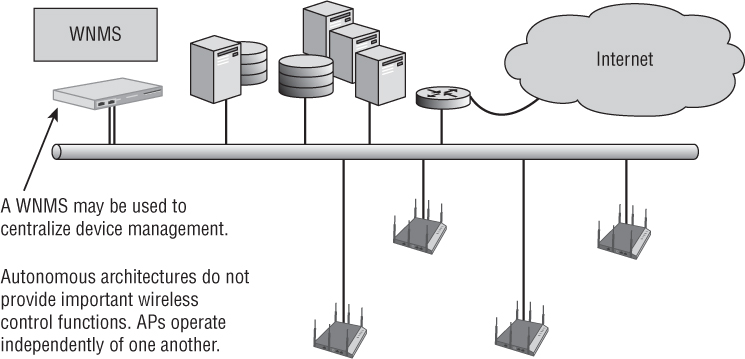
All configuration settings exist in the autonomous access point itself, and therefore, the management plane resides individually in each autonomous AP. All encryption and decryption mechanisms and MAC layer mechanisms also operate within the autonomous AP. The distribution system service (DSS) and integration service (IS) both function within an autonomous AP. The data plane also resides in each autonomous AP because all user traffic is forwarded locally by each individual access point. As shown in Figure 8.1, legacy autonomous APs have little shared control plane mechanisms.
FIGURE 8.1 Autonomous WLAN architecture
An autonomous access point contains at least two physical interfaces: usually a radio frequency (RF) radio and a 10/100/1000 Ethernet port. The majority of the time, these physical interfaces are bridged together by a virtual interface known as a bridged virtual interface (BVI). The BVI is assigned an IP address that is shared by two or more physical interfaces. Access points operate as Layer 2 devices; however, they still need a Layer 3 address for connectivity to an IP network. The BVI is the management interface of an AP.
An autonomous access point typically encompasses both the 802.11 protocol stack and the 802.3 protocol stack. These APs might support the following security features:
Multiple management interfaces, such as command line, web GUI, and SNMP
WEP, WPA, and WPA2 security capabilities
Filtering options, such as MAC and protocol
Autonomous APs might have some of the following advanced security features:
Built-in RADIUS and user databases
VPN client and/or server support
DHCP server
Captive web portals
Autonomous APs are deployed at the access layer and typically are powered by a Power-over-Ethernet (PoE)-capable access layer switch. The integration service within an autonomous AP translates the 802.11 traffic into 802.3 traffic. The autonomous AP was the foundation that WLAN architects deployed for many years. However, most enterprise deployments of autonomous APs were replaced by a centralized architecture utilizing a WLAN controller, which is discussed later in this chapter.
Centralized Network Management Systems
One of the challenges for a WLAN administrator using a large WLAN autonomous architecture is management. As an administrator, would you want to configure 300 autonomous APs individually? One major disadvantage of using the traditional autonomous access point is that there is no central point of management. Any intelligent edge WLAN architecture with 25 or more autonomous access points is going to require some sort of wireless network management system (WNMS).
A WNMS moves the management plane out of the autonomous access points. A WNMS provides a central point of management to configure and maintain thousands of autonomous access points. A WNMS can be a hardware appliance or a software solution. WNMS solutions can be vender specific or vender neutral.
As shown in Figure 8.1, the whole point of a WNMS server was to provide a central point of management for autonomous access points, which are now considered legacy devices. That definition has changed considerably over the years. Later in this chapter, you will learn about WLAN controllers, which are used as a central point of management for controller-based APs. WLAN controllers can effectively replace a WNMS server as a central point of management for access points in small-scale WLAN deployments. However, multiple WLAN controllers are needed in large-scale WLAN enterprise deployments. Currently, most WMNS servers are now used as a central point of management for multiple WLAN controllers in large-scale WLAN enterprises. WNMS servers that are used to manage multiple WLAN controllers from a single vendor may in some cases also be used to manage other vendors’ WLAN infrastructure, including standalone access points.
The term WNMS is actually outdated because many of these centralized management solutions can also be used to manage other types of network devices, including switches, routers, firewalls, and VPN gateways. Therefore, network management server (NMS) is now used more often. NMS solutions are usually vendor specific; however, a few exist that can manage devices from a variety of networking vendors.
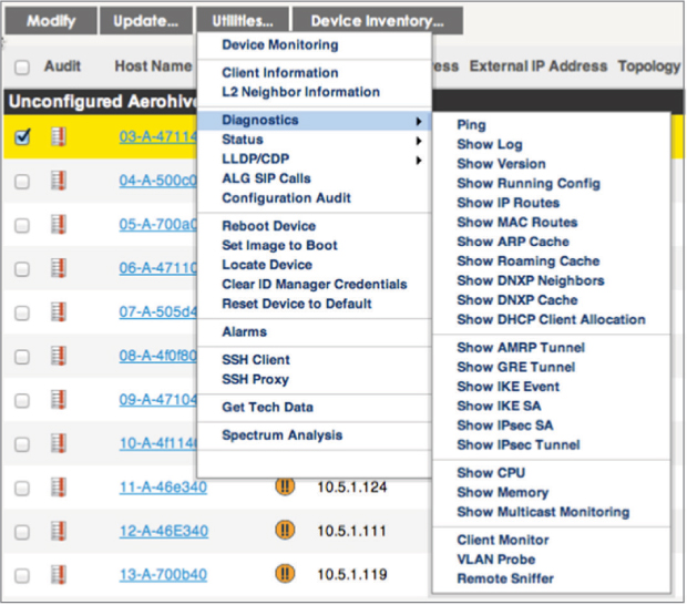
The main purpose of an NMS is to provide a central point of management and monitoring for network devices. Configuration settings and firmware upgrades can be pushed down to all the network devices. Although centralized management is the main goal, an NMS can have other capabilities as well, such as RF spectrum planning and management of a WLAN. An NMS can also be used to monitor network architecture with alarms and notifications centralized and integrated into a management console. An NMS provides robust monitoring of network infrastructure as well as monitoring of wired and wireless clients connected to the network. As shown in Figure 8.2, NMS solutions usually have extensive diagnostic utilities that can be used for remote troubleshooting.
FIGURE 8.2 NMS diagnostic utilities
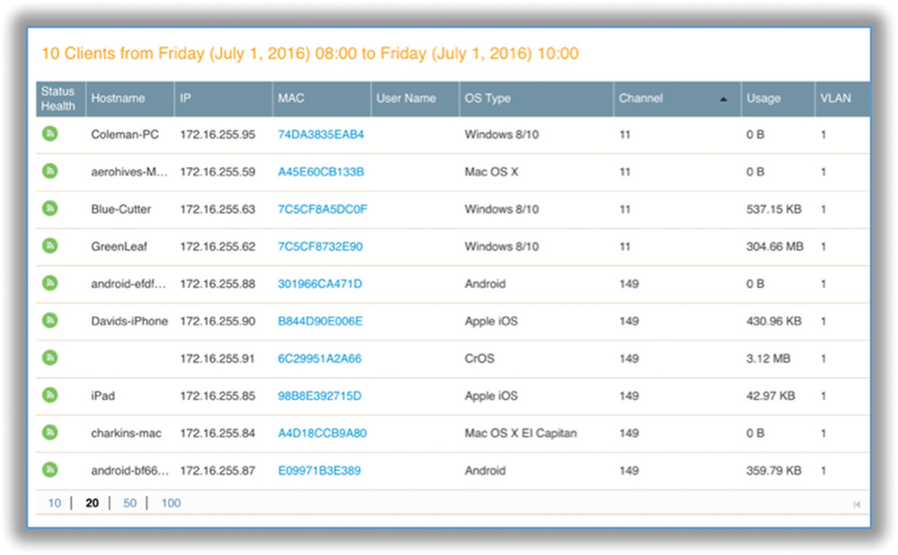
An NMS is a management plane solution; therefore, no control plane or data plane mechanisms exist within an NMS. For example, the only communications between an NMS and an access point are management protocols. Most NMS solutions use the Simple Network Management Protocol (SNMP) to manage and monitor the WLAN. Other NMS solutions also use the Control and Provisioning of Wireless Access Points (CAPWAP) as strictly a monitoring and management protocol. CAPWAP incorporates Datagram Transport Layer Security (DTLS) to provide encryption and data privacy of the monitored management traffic. User traffic is never forwarded by an access point to an NMS; the 802.11 client associations and traffic can be still be monitored. Figure 8.3 shows an NMS display of multiple client associations across multiple APs.
FIGURE 8.3 NMS client monitoring
NMS solutions can be deployed at a company datacenter in the form of a hardware appliance or as a virtual appliance that runs on VMware or some other virtualization platform. A network management server that resides in a company’s own datacenter is often referred to as an on-premises NMS. NMS solutions are also available in the cloud as a software subscription service.
Cloud Networking
Cloud computing and cloud networking are catchphrases used to describe the advantages of computer networking functionality when provided under a Software as a Service (SaaS) model. The term the cloud essentially means a scalable private enterprise network that resides on the Internet. The idea behind cloud networking is that applications and network management, monitoring, functionality, and control are provided as a software service. Amazon is the best example of a company that provides an elastic cloud-based IT infrastructure so other companies can offer pay-as-you-go subscription pricing for enterprise applications and network services.
The most common cloud networking model is cloud-enabled networking (CEN). With CEN, the management plane resides in the cloud, but data plane mechanisms such as switching and routing remain on the local network and usually in hardware. Several WLAN vendors offer cloud-enabled NMS solutions as a subscription service that manages and monitors WLAN infrastructure and clients. Some control plane mechanisms can also be provided with a CEN model. For example, WLAN vendors have begun to also offer subscription-based application services along with their cloud-enabled management solutions. Some examples of these subscriptions services include cloud-enabled guest management, NAC, and MDM solutions.
Centralized WLAN Architecture
The next progression in the development of WLAN integration is the centralized WLAN architecture. This model uses a central WLAN controller that resides in the core of the network. In the centralized WLAN architecture, autonomous APs have been replaced with controller-based access points, also known as lightweight APs or thin APs. Beginning in 2002, many WLAN vendors decided to move to a WLAN controller model where all three logical planes of operation would reside inside the controller. Effectively, all planes were moved out of access points and into a WLAN controller.
Management Plane Access points are configured and managed from the WLAN controller.
Control Plane Dynamic RF, load balancing, roaming handoffs, and other mechanisms exist in the WLAN controller.
Data Plane The WLAN controller exists as a data distribution point for user traffic. Access points tunnel all user traffic to a central controller.
The encryption and decryption capabilities might reside in the centralized WLAN controller or may still be handled by the controller-based APs, depending on the vendor. The distribution system services (DSS) and integration service (IS) both typically function within the WLAN controller. Some time-sensitive operations are still handled by the AP.
WLAN Controller
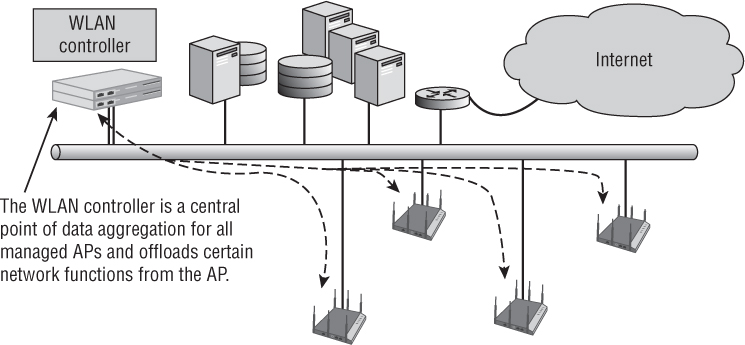
At the heart of the centralized WLAN architecture model is the WLAN controller (see Figure 8.4). WLAN controllers are often referred to as wireless switches because they are indeed an Ethernet-managed switch that can process and route data at the Data-Link layer (Layer 2) of the OSI model. Many of the WLAN controllers are multilayer switches that can also route traffic at the Network layer (Layer 3). However, wireless switch has become an outdated term and does not adequately describe the many capabilities of a WLAN controller.
FIGURE 8.4 Centralized WLAN architecture: WLAN controller
A WLAN controller may have some of these many security features:
VLANs WLAN controllers fully support the creation of VLANs and 802.1Q VLAN tagging. Multiple wireless user VLANs can be created on the WLAN controller so that user traffic can be segmented. VLANs may be assigned statically to WLAN profiles or may be assigned using a RADIUS attribute. User VLANs are usually encapsulated in an IP tunnel.
User Management WLAN controllers usually provide the ability to control the who, when, and where in terms of using role-based access control (RBAC) mechanisms.
Layer 2 Security Support WLAN controllers fully support Layer 2 WEP, WPA, and WPA2 encryption. Authentication capabilities include internal databases, as well as full integration with RADIUS and LDAP servers.
Layer 3 and 7 VPN Concentrators Some WLAN controller vendors also offer VPN server capabilities within the controller. The controller can act as a VPN concentrator or endpoint for IPsec or SSL VPN tunnels.
Captive Portal WLAN controllers have captive portal features that can be used with guest WLANs.
Internal Wireless Intrusion Detection Systems Some WLAN controllers have integrated WIPS capabilities for security monitoring and rogue AP mitigation.
Firewall Capabilities Stateful packet inspection is available with an internal firewall in some WLAN controllers.
Management Interfaces Many WLAN controllers offer full support for common management interfaces such as GUI, CLI, SSH, and so forth.
Controller Data Forwarding Models
A key feature of most WLAN controllers is that the integration service (IS) and distribution system services (DSS) operate within the WLAN controller. In other words, all 802.11 user traffic that is destined for wired-side network resources must first pass through the controller and be translated into 802.3 traffic by the integration service before being sent to the final wired destination. Therefore, controller-based access points send their 802.11 frames to the WLAN controller over an 802.3 wired connection.
The 802.11 frame format is complex and is designed for a wireless medium and not a wired medium. An 802.11 frame cannot travel through an Ethernet 802.3 network by itself. So, how can an 802.11 frame traverse between a controller-based AP and a WLAN controller? The answer is inside an IP-encapsulated tunnel. Each 802.11 frame is encapsulated entirely within the body of an IP packet. Many WLAN vendors use Generic Routing Encapsulation (GRE), which is a commonly used network tunneling protocol. Although GRE is often used to encapsulate IP packets, GRE can also be used to encapsulate an 802.11 frame inside an IP tunnel. The GRE tunnel creates a virtual point-to-point link between the controller-based AP and the WLAN controller. WLAN vendors that do not use GRE use other proprietary protocols for the IP tunneling. The CAPWAP management protocol can also be used to tunnel user traffic.
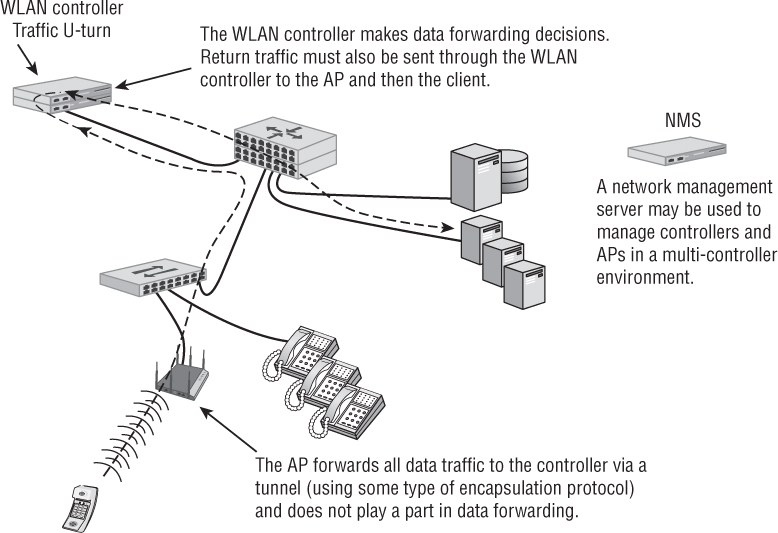
As shown in Figure 8.5, the controller-based APs tunnel their 802.11 frames all the way back to the WLAN controller, from the access layer all the way back to the core layer. The distribution system service inside the controller directs the traffic, whereas the integration service translates an 802.11 data MSDU into an 802.3 frame. After 802.11 data frames have been translated into 802.3 frames, they are then sent to their final wired destination.
Most WLAN controllers are deployed at the core layer; however, they may also be deployed at either the distribution layer or even the access layer. Exactly where a WLAN controller is deployed depends on the WLAN vendor’s solution, and the intended wireless integration into the preexisting wired topology. Multiple WLAN controllers that communicate with each other may be deployed at different network layers, providing they can communicate with each other.
There are two types of data forwarding methods when using WLAN controllers:
Centralized Data Forwarding Where all data is forwarded from the AP to the WLAN controller for processing, it may be used in many cases, especially when the WLAN controller manages encryption and decryption or applies security and QoS policies.
Distributed Data Forwarding Where the AP performs data forwarding locally, it may be used in situations where it is advantageous to perform forwarding at the edge and to avoid a central location in the network for all data, which may require significant processor and memory capacity at the controller.
As shown in Figure 8.5, centralized data forwarding relies on the WLAN controller to forward data. The AP and WLAN controller form an IP encapsulation tunnel, and all user data traffic is passed to the controller for forwarding (or comes from the controller). In essence, the AP plays a passive role in user data handling.
FIGURE 8.5 Centralized data forwarding
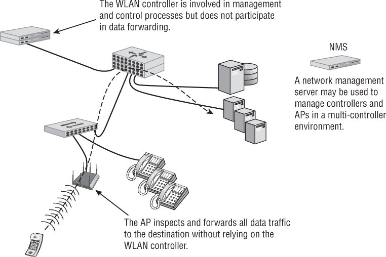
As shown in Figure 8.6, with distributed forwarding scenarios, the AP is solely responsible for determining how and where to forward user data traffic. The controller is not an active participant in these processes. This includes the application of QoS or security policies to data. Generally speaking, the device that handles the majority of MAC functions is also likely to handle data forwarding. The decision to use distributed or centralized forwarding is based on a number of factors, such as security, VLANs, and throughput. One major disadvantage of distributed data forwarding is that some control plane mechanisms may be unavailable because they exist only in the WLAN controller. Control plane mechanisms that may be lost include dynamic RF, Layer 3 roaming, firewall policy enforcement, and fast secure roaming. However, as the controller architecture has matured, some WLAN vendors have also pushed some of the control plane mechanisms back to into the APs at the edge of the network.
FIGURE 8.6 Distributed data forwarding
As 802.11ac technology and bandwidth become increasingly prevalent in large, enterprise networks, centralized data forwarding may become more difficult and expensive due to the traffic loads that can now be generated on the WLAN. Larger controllers with 10 Gbps links will become more commonplace. Additionally, WLAN controller manufacturers are now beginning to embrace distributed data forwarding in different ways.
Remote Office WLAN Controller
Although WLAN controllers typically reside on the core of the network, they can also be deployed at the access layer, usually in the form of a remote office WLAN controller. A remote office WLAN controller typically has much less processing power than a core WLAN controller and is also less expensive. The purpose of a remote office WLAN controller is to allow remote and branch offices to be managed from a single location. Remote WLAN controllers typically communicate with a central WLAN controller across a WAN link. Secure VPN tunneling capabilities are usually available between controllers across the WAN connection. Through the VPN tunnel, the central controller will download the network configuration settings to the remote WLAN controller, which will then control and manage the local APs. These remote controllers will allow for only a limited number of controller-based APs. Features typically include Power over Ethernet, internal firewalling, and an integrated router using NAT and DHCP for segmentation.
Distributed WLAN Architecture
A recent trend has been to move away from the centralized WLAN controller architecture toward a distributed architecture. Some WLAN vendors, such as Aerohive Networks, have designed their entire WLAN system around a distributed architecture. Some of the WLAN controller vendors now also offer a distributed WLAN architecture solution, in addition to their controller-based solution. In these systems, cooperative access points are used, and control plane mechanisms are enabled in the system with inter-AP communication via cooperative protocols. A distributed WLAN architecture combines multiple access points with a suite of cooperative protocols, without requiring a WLAN controller. Distributed WLAN architectures are modeled after traditional routing and switching design models, in that the network nodes provide independent distributed intelligence but work together as a system to cooperatively provide control mechanisms.
As shown in Figure 8.7, the protocols enable multiple APs to be organized into groups that share control plane information between the APs to provide functions such as Layer 2 roaming, Layer 3 roaming, firewall policy enforcement, cooperative RF management, security, and mesh networking. The best way to describe a distributed architecture is to think of it as a group of access points with most of the WLAN controller intelligence and capabilities mentioned earlier in this chapter. The control plane information is shared between the APs using proprietary protocols.
FIGURE 8.7 Distributed WLAN architecture
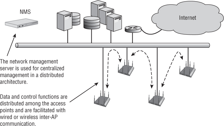
In a distributed architecture, each individual access point is responsible for local forwarding of user traffic. As mentioned earlier, since the advent of 802.11n, WLAN controller vendors have begun to offer distributed data forwarding solutions to handle traffic load. Because a distributed WLAN architecture entirely eliminates a centralized WLAN controller, all user traffic is forwarded locally by each independent AP. In a distributed architecture, the data plane resides in the access points at the edge of the network. No WLAN controller exists; therefore, the data does not need to be tunneled to the core of the network.
Although the control plane and data planes have moved back to the APs in a distributed WLAN architecture, the management plane remains centralized. Configuration and monitoring of all access points in the distributed model is still handled by an NMS server. The NMS server might be an on-premise server or might be offered as a cloud-based service.
Most of the features mentioned in the earlier section about WLAN controllers can also be found in a distributed WLAN architecture even though there is no WLAN controller. For example, a captive web portal that normally resides in a WLAN controller instead resides inside the individual APs. The stateful firewall and RBAC capabilities found in a centralized WLAN controller now exist cooperatively in the APs. Back-end roaming mechanisms and dynamic RF are also cooperative. APs might also function as a RADIUS server with full LDAP integration capabilities. As mentioned earlier, all control plane mechanisms reside in the access points at the edge of the network in a distributed WLAN architecture. The APs implement control plane mechanisms cooperatively using proprietary protocols.
How VLANs are deployed in a WLAN environment depends on the design of the network, as well as the type of WLAN architecture that is in place. One very big difference between using a controller-based model versus a noncontroller model is how VLANs are implemented in the network design. In the WLAN controller model, most user traffic is centrally forwarded to the controller from the APs. Because all the user traffic is encapsulated, a controller-based AP typically is connected to an access port on an Ethernet switch that is tied to a single VLAN.
With a WLAN controller architecture, the user VLANs usually reside in the core of the network. The user VLANs are not available at the access layer switch. The controller-based APs are connected to an access port of the edge switch. The user VLANs are still available to the wireless users because all of the user VLANs are encapsulated in an IP tunnel between the controller-based APs at the edge and the WLAN controller in the core.
The noncontroller model, however, requires support for multiple user VLANs at the edge. Each access point is therefore connected to an 802.1Q trunk port on an edge switch that supports VLAN tagging. All of the user VLANs are configured in the access layer switch. The access points are connected to an 802.1Q trunk port of the edge switch. The user VLANS are tagged in the 802.1Q trunk and all wireless user traffic is forwarded at the edge of the network.
Although the whole point of a cooperative and distributed WLAN model is to avoid centrally forwarding user traffic to the core, the access points may also have IP-tunneling capabilities. Some WLAN customers require that guest VLAN traffic not cross internal networks. In that scenario, a standalone AP might forward only the guest user VLAN traffic in an IP tunnel that terminates at another standalone access point that is deployed in a DMZ. Individual APs can also function as a VPN client or VPN server using IPsec encrypted tunnels across a WAN link.
Another advantage of the distributed WLAN architecture is scalability. As a company grows at one location or multiple locations, more APs will obviously have to be deployed. When a WLAN controller solution is in place, more controllers might also have to be purchased and deployed as the AP count grows. With the controller-less distributed WLAN architecture, only new APs are deployed as the company grows. Many vertical markets such as K–12 education and retail have schools or stores at numerous locations. A distributed WLAN architecture can be the better choice as opposed to deploying a WLAN controller at each location.
Unified WLAN Architecture
WLAN architecture could very well take another direction by fully integrating WLAN controller capabilities into wired network infrastructure devices. WLAN control plane features are being integrated into wired switches, routers, firewalls, and security appliances at both the core and the edge of the network. Solutions that combine management of the wireless and wired networks are gaining in popularity. Customers are often looking for one-box solutions for distributed branch environments. This unified architecture has already begun to be deployed by some vendors and will likely grow in acceptance as WLAN deployments become more commonplace and the need for fuller seamless integration continues to rise.
Hybrid Architectures
It is important to understand that none of the WLAN architectures described in this chapter are written in stone. Many hybrids of these WLAN architectures exist among the WLAN vendors. As was already mentioned, some of the WLAN controller vendors are pushing some of the control plane intelligence back into the access points. One WLAN controller vendor has a cloud-based controller where much of the control plane intelligence exists in the cloud.
Typically, the data plane is centralized when using WLAN controllers, but distributed data forwarding is also available. With a controller-less distributed WLAN architecture, all data is forwarded locally, but the ability to centralize the data plane is a capability of a distributed WLAN architecture.
In a distributed WLAN architecture, the management plane resides in an on-premise or cloud-based network management server. With the WLAN controller model, the management plane normally exists in the WLAN controller. However, the management plane might also be pushed into an NMS that not only manages the controller-based APs but also manages the WLAN controllers.
Enterprise WLAN Routers
In addition to the main corporate office, companies often have branch offices in remote locations. A company might have branch offices across a region or an entire country, or they may even be spread globally. The challenge for IT personnel is how to provide a seamless enterprise wired and wireless solution across all locations. A distributed solution using enterprise-grade WLAN routers at each branch office is a common choice.
Keep in mind that WLAN routers are very different from access points. Unlike access points, which use a bridged virtual interface, wireless routers have separate routed interfaces. The radio card exists on one subnet whereas the WAN Ethernet port exists on a different subnet.
Branch WLAN routers have the ability to connect back to corporate headquarters with VPN tunnels. Employees at the branch offices can access corporate resources across the WAN through the VPN tunnel. Even more important is the fact that the corporate VLANs, SSIDs, and WLAN security can all be extended to the remote branch offices. An employee at a branch office connects to the same SSID that they would connect to at corporate headquarters. The wired and wireless network access policies are therefore seamless across the entire organization. These seamless policies can be extended to the WLAN routers at each branch location.
The enterprise-grade WLAN routers are very similar to the consumer-grade Wi-Fi routers that most of us use at home. However, enterprise WLAN routers are manufactured with better-quality hardware and offer a wider array of features.
The following security features are often supported by enterprise WLAN routers:
802.11 Layer 2 security for wireless clients
802.1X/EAP port security for wired clients
Network address translation (NAT)
Port address translation (PAT)
Port forwarding
Firewall
Integrated VPN client
3G/4G cellular backhaul
WLAN Mesh Access Points
Almost all WLAN vendors now offer WLAN mesh access point capabilities. Wireless mesh APs communicate with each other by using proprietary Layer 2 routing protocols and create a self-forming and self-healing wireless infrastructure (a mesh) over which edge devices can communicate, as shown in Figure 8.8. The main purpose of a mesh WLAN is to provide wireless client access in physical areas where an Ethernet cable cannot be connected to an AP. WLAN client traffic can be sent over wireless backhaul links with an eventual destination to mesh portals that are connected to the wired network.
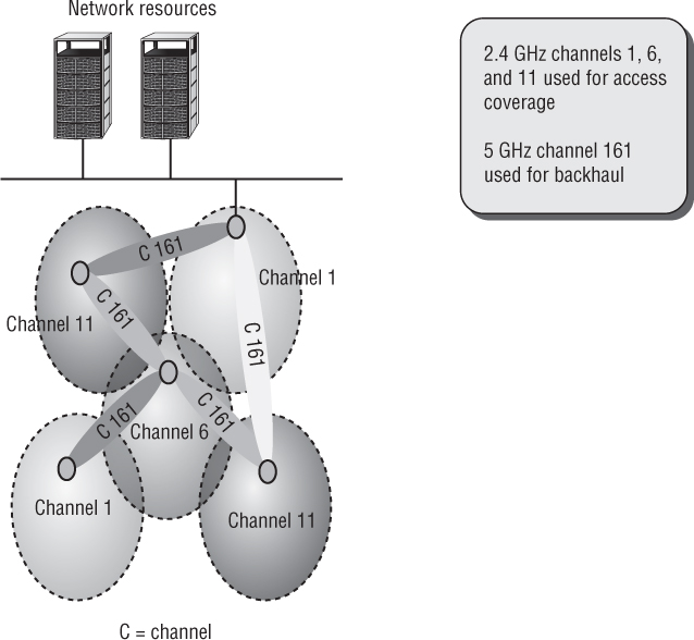
A WLAN mesh network automatically connects access points upon installation and dynamically updates traffic routes as more clients are added. Proprietary Layer 2 intelligent routing protocols determine the dynamic routes based on measurement of traffic, signal strength, data rates, hops, and other parameters.
With dual-band WLAN mesh APs, typically the 5 GHz radios are used for the mesh backhaul communications, as shown in Figure 8.8. The mesh backhaul traffic must also be encrypted. In most cases, 802.11 PSK security is used between the mesh radios to provide encryption. The PSK is usually created automatically in most mesh WLAN solutions. A very strong passphrase of 20 characters or more should be used if the WLAN vendor does offer the option to manually define mesh backhaul security. As you learned in Chapter 6, “PSK Authentication,” the 802.11s-2011 amendment proposed a peer-to-peer authentication method called Simultaneous Authentication of Equals (SAE). Although SAE has yet to be implemented for 802.11 mesh networks, the Wi-Fi Alliance views SAE as an eventual replacement for PSK authentication.
WLAN Bridging
When facilities are separated from each other and no physical network-capable wiring exists between them, wireless bridges are often employed. Monthly-based fees for Telco circuit costs can be mitigated with the one-time cost of a wireless point-to-point (PtP) bridge. Wireless bridges are also used between communication towers and can typically span many miles.
Bridge and backhaul links tend to have very different requirements than do typical AP functions that serve WLAN clients. The first difference is that APs typically serve in the access layer of a network. WLAN bridges operate in the distribution layer and are normally used to connect two or more wired networks together over a wireless link.
One side of the link is usually the root bridge and the other side is the nonroot bridge. The root bridge establishes the channel and beacons for the nonroot bridge to join. The nonroot bridge will then associate with the root bridge in a station-like fashion to establish the link. A point-to-multipoint (PtMP) bridge link connects multiple wired networks. The root bridge is the central bridge, and multiple nonroot bridges connect back to the root bridge.
Encryption is needed to protect the data privacy of the backhaul communications across bridge links. IPSec VPNs are often used for bridge security, which will be discussed later in this chapter. An 802.1X/EAP solution can also be used for bridge security, with the root bridge assuming the authenticator role and the nonroot bridges assuming the supplicant role. Additionally, PSK authentication is often used for WLAN bridge security and therefore a strong WPA2 passphrase of 20 characters or more is recommended.
VPN Wireless Security
Although the 802.11-2012 standard clearly defines Layer 2 security solutions, the use of upper-layer virtual private network (VPN) solutions can also be deployed with WLANs. VPNs are typically not recommended to provide wireless security in the enterprise due to the overhead and because faster, more secure Layer 2 solutions are now available. Although not usually a recommended practice, VPNs were often used for WLAN security because the VPN solution was already in place inside the wired infrastructure. VPNs do have their place in Wi-Fi security and should definitely be used for remote access. They are also sometimes used in wireless bridging environments. The two major types of VPN topologies are router-to-router or client-server based.
Use of VPN technology is mandatory for remote access. Your end users will take their laptops off site and will most likely use public access Wi-Fi hotspots. Because there is no security at most hotspots, a VPN solution is needed. The VPN user will need to bring the security to the hotspot in order to provide a secure, encrypted connection. It is imperative that users implement a VPN solution coupled with a personal firewall whenever accessing any public access Wi-Fi networks.
VPN 101
Before discussing the ways that VPNs are used in a WLAN, it is important to make sure that we review what a VPN is, what it does, how it works, and the components that are configured to construct one. By now you know that a VPN is a virtual private network. But what does that really mean? As shown in Figure 8.9, a VPN is essentially a private network that is created or extended across a public network. In order for a VPN to work, two computers or devices communicate to establish what is known as the VPN tunnel. Typically, a VPN client initiates the connection by trying to communicate with the VPN server.
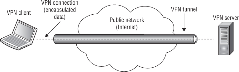
The VPN client can be a computer, router, WLAN controller, or even an AP, which you will learn about later in this chapter. When the client and the server are able to communicate with each other, the client will attempt to authenticate with the server by sending its credentials. The server will take the client’s credentials and validate them. If the client’s credentials are valid, the server and client will create the VPN tunnel between them. Any data that is sent from the VPN client to the VPN server is encapsulated in the VPN tunnel. The client and the server also agree on if and how the data will be encrypted. Prior to the data being encapsulated in the tunnel, the data is encrypted to make sure that, as it travels through the tunnel, it cannot be compromised. Since the underlying premise of a VPN is that the data is traveling across an insecure public network, security is one of the primary reasons for implementing a VPN.
When the client and server build the tunnel, it is their responsibility to route the data across the public network between the two devices. They take the data from the local network, encrypt and encapsulate it, and then send it to the other device, where it is decapsulated and decrypted and then placed on the local network of the other device.
![]() Real World Scenario
Real World Scenario
To understand the concepts of VPNs and encapsulation, imagine a company that has two buildings in a city where the buildings are separated by a distance of two kilometers. Since these buildings are very large, and many people travel between the buildings, the company decides to purchase buses to transport people back and forth between the buildings. The driver of the bus is responsible for driving from the pickup point of the first building to the drop-off point of the second building. The route the driver takes may vary depending on traffic. The employees in the first building know that if they go to the pickup point and board the bus, when they exit the bus they will be at the drop-off location of the second building; just as when the data arrives at the VPN client it will be tunneled and arrive at the VPN server.
The employees are given directions instructing them to get on the bus at the pickup point and to get off the bus at the drop-off point. The employees do not have to understand the route that they are taking through the city. The employees are essentially encapsulated and secured in the climate-controlled bus as they travel between the offices.
In a VPN network, the client and server provide the transportation just as the bus does. The city streets make up the many routes that the bus can take, just as the Internet has many routes that the packets can take. The passengers travel inside the bus just as the data is transmitted inside the packets. The packet is directed through the network just as the bus is directed through the city.
Layer 3 VPNs
VPNs have several major characteristics. They provide encryption, encapsulation, authentication, and data integrity. VPNs use secure tunneling, which is the process of encapsulating one IP packet within another IP packet. The first packet is encapsulated inside the second or outer packet. The original destination and source IP address of the first packet is encrypted along with the data payload of the first packet. VPN tunneling, therefore, protects your original private Layer 3 addresses and also protects the data payload of the original packet. Layer 3 VPNs use Layer 3 encryption; therefore, the payload that is being encrypted is the Layer 4–7 information. The IP addresses of the second or outer packet are seen in clear text and are used for communications between the tunnel endpoints. The destination and source IP addresses of the second or outer packet will point to the public IP address of the VPN server and VPN client software.
The most commonly used Layer 3 VPN technology is Internet Protocol Security (IPsec). IPsec VPNs use stronger encryption methods and more secure methods of authentication and are the most commonly deployed VPN solution. IPsec supports multiple ciphers, including DES, 3DES, and AES. Device authentication is achieved by using either a server-side certificate or a preshared key. IPsec VPNs require client software to be installed on the remote devices that connect to a VPN server. Most IPsec VPNs are NAT-transversal, but any firewalls at a remote site require (at a minimum) that UDP ports 4500 and 500 be open. A full explanation of IPsec technology is beyond the scope of this book, but IPsec is usually the choice for VPN technology in the enterprise.
SSL VPN
VPN technologies do exist that operate at other layers of the OSI model, including SSL tunneling. Unlike an IPsec VPN, an SSL VPN does not require the installation and configuration of client software on the end user’s computer. A user connects to a Secure Sockets Layer (SSL) VPN server via a web browser. The traffic between the web browser and the SSL VPN server is encrypted with the SSL protocol or Transport Layer Security (TLS). TLS and SSL encrypt data connections above the Transport layer, using asymmetric cryptography for privacy and a keyed message authentication code for message reliability.
Although most IPsec VPN solutions are NAT-transversal, SSL VPNs are often chosen because of issues with NAT or restrictive firewall policies at remote locations.
VPN Deployment
VPNs are most often used for client-based security when connected to public access WLANs and hotspots that do not provide security. Because most hotspots do not provide Layer 2 security, it is imperative that end users provide their own security. VPN technology can provide the necessary level of security for remote access when end users connect to public access WLANs. Since no encryption is used at public access WLANs, a VPN solution is usually needed to provide for data privacy, as shown in Figure 8.10.
FIGURE 8.10 VPN established from a public hotspot

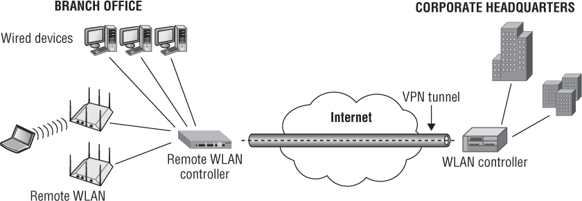
Another common use of VPN technology is to provide site-to-site connectively between a remote office and a corporate office across a WAN link. Most WLAN vendors now offer VPN client-server capabilities in either their APs or WLAN controllers. As shown in Figure 8.11, a branch office WLAN controller with VPN capabilities can tunnel WLAN client traffic and bridged wired-side traffic back to the corporate network. Other WLAN vendors can also tunnel user traffic from a remote AP or WLAN branch router to a VPN server gateway. Third-party VPN overlay solutions are often also used.
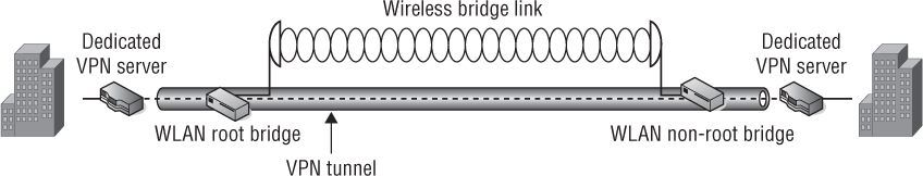
Another use of VPNs is to provide security for 802.11 WLAN bridges links. In addition to using 802.11 wireless technology to provide client access, 802.11 technology is used to create bridged networks between two or more locations. When WLAN bridges are deployed for wireless backhaul communications, VPN technology can be used to provide the necessary level of data privacy. Depending on the bridging equipment used, VPN capabilities may be integrated into the bridges, or you may need to use other devices or software to provide the VPN. Figure 8.12 shows an example of a point-to-point wireless bridge network using dedicated VPN devices. A site-to-site VPN tunnel is used to provide encryption of the 802.11 communications between the two WLAN bridges.
FIGURE 8.12 WLAN bridging and VPN security
Infrastructure Management
Sound network design dictates placing network devices onto dedicated management VLANs or another out-of-band interface from regular network traffic. Enterprise network gear should allow for this functionality in order to keep infrastructure devices inaccessible to hackers or even to employees who are able to gain access to the network.
As the size of WLANs has grown over the years, so have the challenges of managing them. This includes managing the following:
Firmware revisions
Configurations and changes
Monitoring and incident response
Managing and filtering of device alerts and alarms
Performance monitoring
To make the job of managing these devices easier, standard network protocols for device management are typically included in most WLAN hardware and can be integrated with software-based management systems that can span even the largest of networks. The more a network management system (NMS) is incorporated in network designs, the less time is spent performing mundane tasks to support the network. Without exception, every time an NMS is properly implemented, user satisfaction with the network is higher, while the cost of operating the network is lower. Equally important is incorporating the deployment of the NMS into an operational environment with the support staff. Developing processes and procedures around these systems and making them a part of the support staff’s daily work are also critical.
Protocols for Management
There are many different types of protocols used for managing network devices. Simple Network Management Protocol (SNMP) has been around for quite some time and has undergone several revisions. In addition to SNMP, most devices can be configured using a command-line interface (CLI) or a graphical user interface (GUI).
The following protocols are common for managing WLANs. Some of these protocols are based on de jure standards and some are based on de facto standards. Either way, they provide the basis for WLAN management and administration.
SNMP
Simple Network Management Protocol (SNMP) is an Application layer protocol (OSI Layer 7) used to communicate directly with network devices. SNMP allows for pulling information from devices as well as pushing information to a central SNMP server based on certain, often user-configurable thresholds on network devices. A push from a device might include a message pertaining to an interface reset, a high number of errors, high network or CPU utilization, security alarms, and many other critical factors related to the healthy operations and status of devices.
NOTE
SNMP is an IETF specification. You can find more information at www.ietf.org/wg/concluded/snmpv3.html. Additional information can also be found in RFC 3411 through 3418 for SNMP version 3.
Components
An SNMP management system contains
Several (potentially many) nodes, each with an SNMP entity (a.k.a. agent) containing command responder and notification originator applications, which have access to management instrumentation
At least one SNMP entity containing command generator and/or notification receiver applications (traditionally called a manager)
A management protocol used to convey management information between the SNMP entities
Structure of Management Information
Management information is structured as a collection of managed objects contained in a database called a management information base (MIB).
The MIB consists of the following definitions: modules, objects, and traps. Module definitions are used when describing information modules. Object definitions are used when describing the managed objects. Trap definitions are notifications used for unsolicited transmissions of MIB information typically to an NMS.
All SNMP-capable devices have a MIB, and in that MIB should reside the configuration and status of the device. However, vendors aren’t usually totally complete with their MIBs and SNMP implementations. Often you will find that certain pieces of critical information are not accessible via SNMP and therefore traps cannot be implemented using that information.
Versions and Differences
SNMP has undergone numerous revisions over the years. This section is not intended to be a complete history of SNMP, but rather an overview to guide you in knowing the differences between the various versions. Additionally, this section will help you properly implement different versions into your network designs by understanding the strengths and how to address the weaknesses.
SNMPV1
Version 1 of SNMP hit the scene in 1988. Like many other initial protocol introductions, SNMPv1 did not get it perfect the first time. SNMPv1 was designed to work over a wide range of protocols in use at the time—including IP, UDP, CLNS, AppleTalk, and IPX—but it is most commonly used with UDP.
SNMPv1 used a community string, which had to be known by a remote agent. Since SNMPv1 did not implement any encryption, it was subject to packet sniffing to discover the clear-text community string. Therefore, SNMPv1 was heavily criticized as being insecure. Protocol efficiency was also lacking for this initial protocol introduction. Each MIB object had to be retrieved one by one in an iterative style, which was very inefficient.
SNMPV2
When SNMPv2 was released, several areas of SNMPv1 were addressed, including performance, security, and manager-to-manager communications. Protocol performance became more efficient with the introduction of new functions such as GETBULK, which solved the iterative method of extracting larger amounts of data from MIBs.
Security was improved by the specification of a new party-based security system. Critics accused the party-based system of being too complex, and the system was not widely accepted.
SNMPv2c was later defined in RFCs 1901 through 1908 and is referred to as the community-based version. The community string from SNMPv1 was adopted in SNMPv2c, which essentially dropped any security improvements to the protocol. SNMPv2c does not implement encryption and is subject to packet sniffing of the clear-text community string.
SNMPV3
A great deal of security benefits were added to SNMPv3, including
Authentication performed using SHA or MD5.
Privacy—SNMPv3 uses DES 56-bit encryption based on the CBC-DES (DES-56) standard.
Access control—Users and groups are used, each with different levels of privileges. Usernames and passwords replace community strings.
Although these features are optional, usually the main driver behind adopting SNMPv3 is to gain these security benefits. It is also optional to have secure authentication but disable encryption.
Even with these features, most network designers still feel it is best to implement the SNMP agents only on secure management interfaces. Specifically, VLAN segmentation and firewall filtering is usually performed on all SNMP traffic to network devices. No sufficiently complex protocol is considered completely secure, and additional safeguards are always highly recommended. If you intend to implement an NMS using SNMP, we highly recommended that you implement SNMPv3. One of the most important security concerns is most vendor equipment defaults to SNMP being enabled, with default read and write community strings. This is an enormous security threat to the configuration and operation of your network, and should be one of the very first lockdown steps to securing network devices.
CLI-Based Management
Command-line interfaces (CLIs) are one of the most common methods used to configure and manage network devices. It seems the age-old debate of GUI versus CLI is still present to this day and is not likely to change any time soon. GUIs do a wonderful job of presenting information, but due to browser incompatibility, JavaScript errors, GUI software bugs, time delays, and more, GUIs still drive many people back to the command line.
CLIs tend to be the raw, unedited configuration of devices and provide the ability to make specific changes quickly to device configurations. Commands issued via a CLI can even be scripted, allowing initial device configuration and even reconfigurations to be performed with a simple copy and paste into a CLI session.
CLIs can be accessed using several methods, which are dependent on the device being used. These commonly include the following:
Serial and console ports
Telnet
SSH1/SSH2
Serial and Console Ports
Serial or console port interfaces can vary from manufacturer to manufacturer and even from model to model. This is extremely frustrating to network engineers. Some of them use a standard DB-9 serial connector interface, whereas others use an RJ-11 or RJ-45 interface. Furthermore, the actual cable might be a proprietary pin-out (namely for the RJ-11 and RJ-45 connectors), a NULL-modem cable, a rollover cable, or a straight-through cable. Baud rates, number of bits, flow control, parity, and other parameters also vary from device to device.
No matter what type of connector or cable you are using to manage your network device, serial or console ports should be locked down and require a user authentication mechanism. Although typically these can be thwarted by a password-recovery routine using instructions that can be readily found on the Internet, a user authentication mechanism will help deter hackers. Often, a device requires downtime in order to recover the password, and the impact of a service outage may be enough to alert staff of a physical break-in attempt to network devices. It is important to note that most password recovery routines require direct access to the device via the serial or console port. Securing network equipment in a locked data closet or computer room will help to prevent this type of attack from occurring.
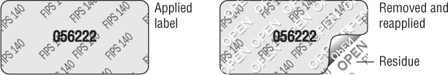
Government regulations such as FIPS 140-2 may require that serial and console ports be secured with a tamper-evident label (TEL) to prevent unauthorized physical access to a WLAN infrastructure device such as a WLAN controller. TELs cannot be surreptitiously broken, removed, or reapplied without an obvious change in appearance. As shown in Figure 8.13, each TEL has a unique serial number to prevent replacement with similar labels.
FIGURE 8.13 Tamper-evident label
Telnet
Telnet is another protocol that is commonly used, but often it can only be used after a serial port configuration or initial configuration from a factory default state is performed. The IP of the device typically needs to be enabled for it to be accessed and managed via the network interface.
Telnet is heavily criticized and usually prohibited from use by enterprise security policies due to its lack of encryption. Telnet is a completely unencrypted protocol and the payload of each packet can be inspected by packet sniffing. This includes the username and password during the login sequence. We recommend that you disable Telnet after the initial device configuration. Most companies have written policies mandating that Telnet be disabled.
Secure Shell
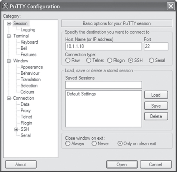
Secure Shell (SSH) is typically used as the secure alternative to Telnet. SSH implements authentication and encryption using public-key cryptography of all network traffic traversing between the host and user device. The features of Telnet for CLI-based management apply to SSH but include added security benefits. The standard TCP port 22 has been assigned for the SSH protocol. Most WLAN infrastructure devices now support the second version of the SSH protocol, called SSH2. As a matter of policy, when WLAN devices are managed via the CLI, an SSH2-capable terminal emulation program should be used. Figure 8.14 shows the configuration screen of the popular freeware program PuTTY, which supports SSH2.
FIGURE 8.14 PuTTY freeware SSH2 client
HTTPS
Hypertext Transfer Protocol Secure (HTTPS) is a combination of the Hypertext Transfer Protocol with the SSL/TLS protocol to provide encryption and secure identification. HTTPS is essentially an SSL session that uses HTTP and is implemented on network devices for management via a graphical user interface (GUI). Not all users prefer CLI-based management methods, and GUIs are commonly used where an NMS is used to manage WLAN infrastructure.
Because HTTP is transmitted in plaintext, it is susceptible to eavesdropping and man-in-the-middle attacks from modifications in transit. Some devices offer both HTTP and HTTPS, but it is important that minimal authentication be performed via HTTPS. If users of devices will be entered into the GUI, not using HTTPS is purely negligent if the device supports it.
Summary
WLAN security plays an integral part of client device performance. With wired LANs, firewalls are placed between networks where network activity needs to be policed. The security a wired-side firewall provides does not affect the installation or configuration of a wired client device.
IEEE 802.11 WLANs operate very differently. Security choices greatly affect the design, architecture, and type of clients that can run over the WLAN. In fact, the opposite is true as well. The devices themselves and their criticality to the business might dictate changes or exceptions to security policy. Because a WLAN is a network-based technology, we typically relate WLAN security and methodologies to the model of how wired LANs work. As you have gathered from your reading of this book, that couldn’t be further from the truth. WLAN performance is tightly interwoven with WLAN security, RF propagation and design, as well as infrastructure features and capabilities. Hardly any technology architecture we commonly use today has this level of integration and co-dependency.
By reading this chapter, you have learned about the important components involved in enterprise security solutions from the infrastructure perspective and also understand the basic security design issues involved.
Exam Essentials
Define the three logical network planes of operation. Understand the differences between the management, control, and data plane. Be able to explain where they are used within different WLAN architectures.
Understand types of WLAN architectures. Know the different types of architectures, including autonomous, centralized, distributed, unified, and hybrid.
Understand common infrastructure device features and features that pertain to security. Know design details and security components of infrastructure and device features.
Be familiar with device management features. Know the various device management methods, features, and protocols available in WLAN devices.
Understand VPNs and WLANs. Explain VPN basics and the various ways IPsec VPNs are used for WLAN security.
Review Questions
1. Which terms best describe components of a centralized WLAN architecture where the management, control, and data planes all reside in a centralized device? (Choose all that apply.)
A. WLAN controller
B. Wireless network management system
C. Network management system
D. Distributed AP
E. Controller-based AP
2. Which logical plane of network operation is typically defined by protocols and intelligence?
A. User plane
B. Data plane
C. Network plane
D. Control plane
E. Management plane
3. Which WLAN architectural models typically require support for 802.1Q tagging at the edge on the network when multiple user VLANs are required? (Choose all that apply.)
A. Autonomous WLAN architecture
B. Centralized WLAN architecture
C. Distributed WLAN architecture
D. None of the above
4. What type of WLAN security is normally used to encrypt and provide data privacy for 802.11 traffic that traverses across mesh backhaul links?
A. 802.1X/EAP
B. SAE
C. PSK
D. IPsec
E. VRRP
5. Which protocols can be used to tunnel 802.11 user traffic from access points to WLAN controllers or other centralized network servers? (Choose all that apply.)
A. IPsec
B. GRE
C. CAPWAP
D. DTLS
E. VRRP
6. Which of these WLAN architectures may require the use of an NMS server to manage and monitor the WLAN?
A. Autonomous WLAN architecture
B. Centralized WLAN architecture
C. Distributed WLAN architecture
D. All of the above
7. How are IPsec VPNs used to provide security in combination with 802.11 WLANs?
A. Client-based security on public access WLANs
B. Point-to-point wireless bridge links
C. Connectivity across WAN links
D. All of the above
8. What are of some of the common security capabilities often found in a WLAN controller?
A. VPN server
B. Firewall
C. RADIUS server
D. WIPS
E. All of the above
9. What is the traditional data forwarding model for 802.11 user traffic when WLAN controllers are deployed?
A. Distributed data forwarding
B. Autonomous forwarding
C. Proxy data forwarding
D. Centralized data forwarding
E. All of the above
10. What are some of the security capabilities found in an enterprise WLAN router that is typically deployed in remote branch locations? (Choose all that apply.)
A. Integrated WIPS server
B. Integrated VPN server
C. Integrated NAC server
D. Integrated firewall
E. Integrated VPN client
11. What are the best and most often used security solutions used to provide data privacy across 802.11 WLAN bridge links? (Choose all that apply.)
A. 802.1X/EAP
B. Captive web portal
C. Firewall
D. IPsec VPN
E. PSK
F. Mobile device management
12. Which of these protocols can be used to manage WLAN infrastructure devices?
A. HTTP
B. SSH
C. SNMP
D. Telnet
E. HTTPS
F. SNMP
G. All of the above
13. What components make up a distribution system? (Choose all that apply.)
A. HR-DSSS
B. DSS
C. DSM
D. DSSS
E. WIDS
14. Which management protocols are often used between a network management server (NMS) and remote access points for the purpose of monitoring a WLAN? (Choose all that apply.)
A. IPsec
B. GRE
C. CAPWAP
D. DTLS
E. SNMP
15. What are of some of the common security capabilities often integrated within in access points deployed in a distributed WLAN architecture?
A. Captive web portal
B. Firewall
C. Integrated RADIUS
D. WIPS
E. All of the above
16. What are some of the major differences between SNMPv3 and SNMPv2? (Choose all that apply.)
A. SNMPv3 requires username/passwords.
B. SNMPv3 requires community strings.
C. SNMPv3 uses 56-bit DES encryption to encrypt packets.
D. SNMPv3 uses 128-bit AES encryption to encrypt packets.
17. What is the biggest security risk associated with Simple Network Management Protocol (SNMP)?
A. DES encryption can be cracked.
B. Weak data integrity.
C. Lack of vendor support.
D. Default community strings.
18. What layers of the OSI model are protected by encryption with an IPsec VPN security solution?
A. Layers 2–7
B. Layers 3–7
C. Layers 4–7
D. Layers 5–7
E. Layers 6–7
19. What are the available form factors for network management server (NMS) solutions? (Choose all that apply.)
A. Hardware appliance
B. Virtual appliance
C. Software subscription service
D. Integrated access point
20. What planes of operation reside in the access points of a distributed WLAN architecture? (Choose all that apply.)
A. Radio plane
B. Data plane
C. Network plane
D. Control plane
E. Management plane