Chapter 9
Thermochemical Sensors
Thermochemical transduction is intrinsically a universal method being based on a property common to a large number of chemical reactions, namely, the generation of heat by exothermal reactions. The thermal effect of a chemical reaction is indicated by the standard enthalpy of reaction (![]() , in kJ mole−1), which represents the change in the energy of the system at normal temperature and pressure when one mole of reactant is transformed by a chemical reaction.
, in kJ mole−1), which represents the change in the energy of the system at normal temperature and pressure when one mole of reactant is transformed by a chemical reaction.
Catalytic reactions are particularly suited for applications in chemical sensors since a large amount of reactant can be converted in a small catalytic reactor to produce a local change in temperature. This effect is quantified by means of a temperature transducer. Under steady-state conditions, the temperature variation with respect to a reference sensor indicates the concentration of the analyte in the sample. The steady state can be achieved by feeding the fluid sample to the reactor at a constant rate.
This chapter introduces first typical temperature transducers employed in thermochemical sensors and then presents two types of thermal sensors, namely enzymatic thermal sensors and thermocatalytic gas sensors.
9.1 Temperature Transducers
In order to convert temperature variations into an electric signal, two main kinds of transducer are used, namely resistive transducers and transducers based on the thermoelectric effect [1]. In the first case, the resistivity of the device varies with the temperature, whereas in the second case the device is a thermocouple that generates an electric voltage depending on the temperature difference between two points.
9.1.1 Resistive Temperature Transducers
Resistance thermometers, also called resistance temperature detectors or resistive thermal devices (RTDs), are temperature transducers that exploit the change in electrical resistance (R) of thin platinum wires whose resistivity increases with the temperature as:
(9.1) ![]()
where R0 is the resistance at normal temperature T0, and ![]() is the temperature coefficient.
is the temperature coefficient.
Another type of temperature transducer is the thermistor, which is a ceramic semiconductor device made of oxides of transition metals. Most thermistors have a negative temperature coefficient; that is, their resistance decreases with increasing temperature. Over a narrow temperature region the change in resistance is directly proportional to the temperature change.
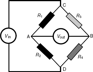
In order to detect small resistance modifications the resistive temperature transducer is incorporated in a Wheatstone resistor bridge, which is a four resistor circuit as shown in Figure 9.1. A DC voltage is applied between the points C ad D and the output voltage is measured between A and B. It is easy to demonstrate that, if ![]() , the output voltage is zero. Very small deviations from the above condition give rise to a nonzero output voltage. In a thermochemical sensor setup, the actual sensor (R4) is coupled with a reference sensor (R3) whose temperature is not affected by the reaction. Measurement of the output bridge voltage allows detection of temperature variations down to 0.005 K.
, the output voltage is zero. Very small deviations from the above condition give rise to a nonzero output voltage. In a thermochemical sensor setup, the actual sensor (R4) is coupled with a reference sensor (R3) whose temperature is not affected by the reaction. Measurement of the output bridge voltage allows detection of temperature variations down to 0.005 K.
Figure 9.1 Wheatstone bridge circuit diagram. Vin is the applied DC voltage; Vout is the output bridge voltage; R1 and R2 are simple resistors. R4 indicates the transducer resistance and R3 is the resistance of a reference sensor.
9.1.2 Thermopiles
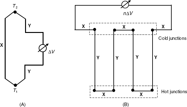
The basis of the thermopile is the thermoelectric effect, that is, conversion of the temperature difference directly into an electrical voltage in a device called thermocouple (Figure 9.2A). The thermocouple consists of a loop formed by two different materials (metals or semiconductors). The output voltage (ΔV) is proportional to the temperature difference between the two junctions, that is:
Figure 9.2 A thermocouple (A) and a thermopile (B). X and Y denote two different conducting materials; n is the number of thermocouples.
(9.2) ![]()
where ![]() (the relative Seebeck coefficient) depends upon the composition of the materials X and Y and upon the working temperature; it is approximately constant over a narrow temperature range. In order to increase the output voltage, thermocouples are connected in series to yield a thermopile (Figure 9.2B). The output voltage of this device is
(the relative Seebeck coefficient) depends upon the composition of the materials X and Y and upon the working temperature; it is approximately constant over a narrow temperature range. In order to increase the output voltage, thermocouples are connected in series to yield a thermopile (Figure 9.2B). The output voltage of this device is ![]() , where
, where ![]() is the number of thermocouples. When the cold junctions are maintained at constant temperature and the hot junctions are exposed to the heat evolved by a chemical reaction, the output voltage is related to the reactant concentration. Thermopiles can be fabricated easily on integrated circuits and display substantial advantages as compared with thermistors as far as sensitivity, noise cancellation and response time are concerned.
is the number of thermocouples. When the cold junctions are maintained at constant temperature and the hot junctions are exposed to the heat evolved by a chemical reaction, the output voltage is related to the reactant concentration. Thermopiles can be fabricated easily on integrated circuits and display substantial advantages as compared with thermistors as far as sensitivity, noise cancellation and response time are concerned.
9.2 Enzymatic Thermal Sensors
9.2.1 Principles of Thermal Transduction in Enzymatic Sensors
Enzyme-catalyzed reactions are exothermic processes that allow for thermometric transduction in enzymatic sensors. Even when the substrate reaction is not thermally efficient, further heat can be generated by incorporating a subsequent enzymatic reaction. For example, if hydrogen peroxide is one of the primary products, catalase can be added in order to dissociate the H2O2 into water and oxygen to produce an appreciably enhanced thermal effect. A typical example of this kind is the determination of glucose using the glucose oxidase-catalyzed reaction. Additionally, proton exchange reactions involving a buffer component also contribute to an increase in the overall thermal effect; The Tris buffer (tris-(hydroxymethyl)aminomethane) is particularly effective in this respect.
A thermal enzymatic sensor can be looked upon as a microcalorimeter with the biological component closely integrated with a temperature transducer. This kind of analytical device was first developed in 1974 [2, 3] and the technology has progressed steadily since then [4–6]. Manufacturing protocols for thermal enzymatic sensors can be found in ref. [7].
Changes in temperature caused by the enzymatic reaction can be probed by various temperature transducers, the thermistor being the most common.
The rate of heat production at the surface of the thermal transducer is limited by the diffusion of reactants but heat dissipation is a much faster process and this prevents substantial changes in temperature. In order to minimize heat dissipation, the overall sensor-solution system should be as small as possible. As organic solvents have lower thermal capacities than water, use of such solvents brings a significant improvement in sensitivity.
9.2.2 Thermistor-Based Enzymatic Sensors
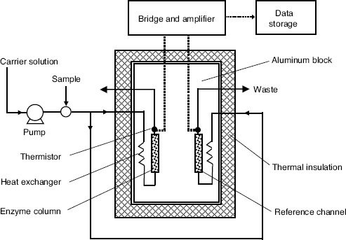
The typical configuration of a thermal enzymatic analyzer is shown in Figure 9.3. The overall analysis system consists of two components, the enzyme thermistor calorimeter and the flow-injection system. A carrier buffer solution is pumped steadily to the calorimeter, and the stream is split so as to reach both the analytical and reference columns. The first column is filled with about 1 ml of biocatalytic material (for example, an enzyme immobilized by glutaraldehyde cross linking on controlled-pore glass beds). The second column is packed with inactive material. Before the buffer solution reaches the columns, the fluid temperature is stabilized by means of heat exchangers. Downstream from the columns, transducers are installed in order to detect the temperature changes in the effluent. The temperature changes are detected by a Wheatstone bridge and the output voltage is amplified and fed to the data storage and processing unit.
Figure 9.3 Configuration of a microcalorimetric enzyme analysis system.
An important working parameter of this analyzer is the carrier flow rate. It should be selected so as to secure a sufficiently long contact time between the sample and the enzyme filling in order to achieve a sufficiently high substrate conversion, and, as a result, a suitably large heat output. The analysis system can be operated either in flow-injection mode or in flow-through mode. In the flow-injection mode, a limited volume of sample is carried to the column by a stream of buffer solution. The output is a peak-shaped ΔT vs. time curve. For quantitation purpose, either the peak height or the integrated signal (peak area) are correlated with the substrate concentration. Conversely, in the flow-through mode, a stream of substrate-containing solution is supplied continuously to the enzyme reactor that results in a greater ![]() value as compared with the flow-injection mode.
value as compared with the flow-injection mode.
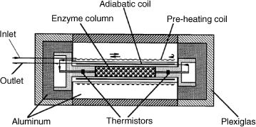
An alternative to the dual column system is presented in Figure 9.4. Here, the reference thermistor is installed before the catalytic column. The device in this Figure is a miniaturized one being suitable for 0.1 μl samples. The main unit is a stainless steel column packed with controlled-pore glass beds carrying an enzyme.
Figure 9.4 Miniaturized single-column thermal biosensor (54 mm in length and 24 mm in diameter). The enzyme column is 1.5/1.7 mm inner diameter/outer diameter and 15 mm in length. Arrows show the flow direction. Reproduce with permission from [6]. Copyright 2000 Elsevier.
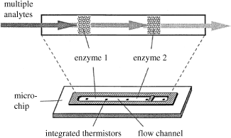
The most remarkable progress in this field has arisen from the application of integrated circuit technology to manufacture integrated microsystems. As demonstrated in Figure 9.5, this technology enables the construction of multianalyte sensors by integrating a series of enzyme columns and transducers in order to detect a range of substrates. The size of such a system can be as little as 10 mm, with the enzyme being immobilized directly onto the surface of microchannels etched within the wafer.
Figure 9.5 Schematics of an integrated thermal sensor array based on a combination of different enzyme columns. Reproduce with permission from [6]. Copyright 2000 Elsevier.
9.2.3 Thermopile-Based Enzymatic Sensors
An integrated thermal biosensor using a thermopile as transducer has been manufactured by microelectromechanical systems technology. It consists of a polymer microfluidic structure (chambers and channels) integrated with a silicon-based thermal transducer chip [8]. Enzyme-activated microbeads were loaded into the chambers using the inlet channels and were confined inside by a weir structure located at the junction between each chamber and its outlet channel. Chambers lie on a polymer diaphragm on which the thermopile is integrated in the form of thin-film chromium-nickel junctions. Metal resistive microheaters are included for device calibration and temperature control. Air gaps around each chamber as well as the plastic diaphragm provide a good thermal insulation.
Such a microfluidic device can be used in conjunction with a subcutaneous sampling method, such as microdialysis. The structure allows the handling of biological samples of very low volume (0.8 μl).
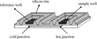
A gain in sample throughput is obtained if the microplate array format is used for the calorimetric detection of low molecular analytes. The transduction principle is based on the differential measurement of the heat generated between two wells, located at the cold and the hot junctions of a thermopile (Figure 9.6). The response is the difference in temperature between the active well the reference well (where no specific reaction takes place). Tens or hundreds of wells can be engraved on a wafer. The thermopiles are fabricated by integrated circuit technology as combinations of 64 aluminum-p-silicon thermocouples. As the required amount of enzyme is extremely small, dissolved enzyme can be dispensed to each measuring well instead of immobilizing it. Samples and reagents are dispensed by means of a software-controlled microdispenser. The feasibility of such a device was demonstrated by ascorbic acid determination using ascorbates oxidase-catalyzed oxidation by oxygen. In contrast to the sequential operation mode of a flow-injection analysis system, the microplate array allows simultaneous analysis of a great number of samples of volume in the nanoliter range.
Figure 9.6 Structure of a microplate differential calorimeter. A full microplate consisted of 48 couples of wells. Reproduce with permission from [9]. Copyright 2007 American Chemical Society.
9.2.4 Multienzyme Thermal Sensors
In general, the limit of detection of single-enzyme thermal biosensors is rather poor (10−4 M) and the response range (10−4 – 10−2 M) is relatively narrow for the majority of applications. Better performances are obtained for the more exothermic reactions (e.g., catalase). Sensitivity is substantially enhanced by increasing the heat output based on substrate or coenzyme recycling in multienzyme systems [4]. For example, a 1000-fold enhanced sensitivity was achieved for lactate or pyruvate by using coimmobilized lactate oxidase and lactate dehydrogenase (Figure 9.7A) [10]. The heat effect is enhanced by the decomposition of peroxide catalyzed by the catalase enzyme. This configuration allows the determination of lactate or pyruvate down to the 10 nM level.
Figure 9.7 (A) Substrate recycling for thermal enzyme sensor applications. LOD = lactate oxidase; LDH = lactate dehydrogenase; CAT = catalase; (B) Coenzyme recycling for determining NAD(H). GDH = glucose-6-phosphate dehydrogenase; LDH = lactate dehydrogenase.
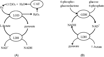
An enlightening example of coenzyme recycling application refers to a device using the highly exothermic oxidation of NADH (![]() ). The cycling process depicted in Figure 9.7B considerably enhances the sensitivity of NAD(H) determination by means of coimmobilized lactate dehydrogenase and glucose-6-phosphate dehydrogenase using glucose-6-phosphate and pyruvate, respectively, as substrates.
). The cycling process depicted in Figure 9.7B considerably enhances the sensitivity of NAD(H) determination by means of coimmobilized lactate dehydrogenase and glucose-6-phosphate dehydrogenase using glucose-6-phosphate and pyruvate, respectively, as substrates.
9.2.5 Outlook
In summary, what is usually termed as a thermal biosensor is in effect a kind of plug-flow enzyme reactor integrated with a temperature transducer incorporated within a microcalorimeter structure. The reactor can be configured in the packed-bed form, but tubular reactors, with the enzyme immobilized on the channel wall (e.g., nylon) can be a suitable alternative in some instances. The second configuration is advantageous when clogging of the packed beds may occur.
Thermal sensors have been designed for a large variety of applications including the determination of metabolites, bioprocess monitoring, and environmental control by means of enzyme inhibition [4, 11]. The main advantage of the thermal sensor is its general applicability. As the temperature change induced by a simple enzymatic reaction is relatively low, an improvement in the limit of detection can be achieved by additional reactions that enhance the heat output. Further progress in this field will arise from miniaturization and increased automation, as well as from improved integration with microfluidic systems in order to increases the sample throughput and reduce the amount of reagents required.
9.3 Thermocatalytic Sensors for Combustible Gases
Determination of various combustible gases is a stringent issue in mining and industry where accumulation of such gases brings about the risk of fire or explosion. Among the various types of combustible gas sensors, the catalytic type was the first to be produced on an industrial scale, and still arouses interest, despite the subsequent advent of more advanced gas sensors. This topic is well covered in refs. [12–14].
9.3.1 Structure and Functioning Principles
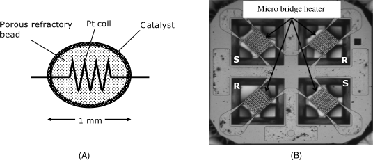
The typical configuration of a thermocatalytic gas sensor is shown in Figure 9.8A. It consists of a porous ceramic bead (typically alumina) into which is embedded a temperature-sensitive platinum coil resistor. The external layer of the bead contains a finely dispersed catalyst that is usually a platinum-group metal. Alternatively, the catalyst can be included through the whole ceramic bead. Commonly, this kind of gas sensor is termed a pellistor, the word being derived from “catalytic pelletized resistor”. Other temperature probes, such as the thermistor or the thermocouple, can also be use in the thermocatalytic gas sensors.
Figure 9.8 (A) The standard configuration thermocatalytic gas sensor (pellistor). Although this device is very small, the overall size is increased by the additional reference element and bridge resistors. (B) A platform for thermocatalytic gas sensors (2.4 × 2.4 mm) produced by micromachining. S means sensor; R means reference element. (B) Adapted with permission from [16]. Copyright (2011) Elsevier.
In operation, the device is heated to 400–800 °C by passing a current through the Pt coil. In the presence of a combustible gas or vapor, the catalyst promotes the analyte combustion that causes the temperature of the device to increase. As a result, the resistance of the Pt wire also increases. The change in the resistance can be detected by a Wheatstone bridge circuit that permits the determination of the content of the gas of interest. Clearly the platinum wire serves as both heater and temperature transducer.
In order to enhance the thermal effect, the device should be fitted with effective thermal insulation. On the other hand, it should allow for efficient heat transfer from the reaction zone to the temperature probe.
A thermocatalytic gas sensor responds, in principle, to any flammable gas or vapor. However, some degree of selectivity can be achieved by proper selection of the operating temperature and the nature of the catalyst. Interfering gases can be retained by a sorbent filters installed between the sensor and the sample gas. A filter can also provide protection against damaging gases such as H2S, SO2, NO2 or mercaptans that are catalyst poisons.
Fabrication of a standard pellistor, like that in Figure 9.8A involves much handwork. Progress in thermoelectric gas sensor technology came about with the introduction of thick-film technology that made possible the production of sensors in a planar configuration (see e.g., [15]).
Currently, research interest in thermocatalytic gas sensors is directed towards designing miniaturized devices and producing them by micromachining technology. As an example, Figure 9.8B shows a platform for thermocatalytic gas sensors fabricated by micromachining on a silicon support coated with silicon dioxide and silicon nitride. Platinum has been deposited over cavities in the support so as to form four suspended resistors connected in a bridge circuit. Platinum layers provide heating and, at the same time, act as temperature probes. In order to obtain a sensor, alumina-supported catalyst films have been deposited over two opposite platinum layers, while the remaining two have been coated with plain alumina to form reference elements. This circuit deviates from the standard bridge configuration (Figure 9.1) that includes only one sensor and one reference element.
Suspended mounting of the platinum heater, as well as the small size of the device minimize heat loss to the support and the ambient atmosphere and hence provide good sensitivity.
The platform in Figure 9.8B has been employed to develop a hydrogen sensor using platinum as catalyst. Catalyzed combustion of hydrogen to water occurs with a very high reaction rate and, as a result, the sensor response to hydrogen is much greater than the response to various hydrocarbons, ethanol, and ether vapors.
Attempts at developing arrays of crossreactive thermocatalytic gas sensors have also been performed based on the effect of the catalyst nature upon the response to various gases. For example an array of four sensor has been designed to be used for the determination of methane, propane and ethanol vapors based on neural network data analysis [17]. The response of each individual sensor to a particular gas has been tuned by means of the catalyst nature (Pt or Pd), catalyst concentration and using mixtures of the above catalysts.
Despite the advent of other types of gas sensor, thermocatalytic gas sensors are still of interest in traditional applications such as detection of certain hazardous gases as well as in fire or explosion alarms. This is due to the extremely simple design and facile fabrication. As these devices should be operated at elevated temperature, the power consumption is a limiting parameter. Progress in this area is still possible by applications of advanced fabrication technologies that allow for inexpensive mass production of devices characterized by low power consumption, as well as for developing arrays of crossreactive sensors. The array approach can alleviates for the poor selectivity of thermocatalytic gas sensors.
1. Sinclair, I.R. (2001) Sensors and Transducers, Newnes, Boston.
2. Mosbach, K. and Danielsson, B. (1974) Enzyme thermistor. Biochim. Biophys. Acta, 364, 140–145.
3. Cooney, C.L., Weaver, J.C., Tannenbaum, S.R. et al. (1974) Thermal enzyme probe: A novel approach to chemical analysis, in Enzyme Engineering (eds E. Kendall Pye and L.B. Wingard), Plenum, New York, pp. 411–417.
4. Danielsson, B. and Windquist, F. (1990) Thermometric sensors, in Biosensors: A Practical Approach (ed. A.E.G. Cass), IRL Press, Oxford, pp. 191–209.
5. Ramanathan, K. and Danielsson, B. (2001) Principles and applications of thermal biosensors. Biosens. Bioelectron., 16, 417–423.
6. Xie, B., Ramanathan, K., and Danielsson, B. (2000) Mini/micro thermal biosensors and other related devices for biochemical/clinical analysis and monitoring. TrAC-Trends Anal. Chem., 19, 340–349.
7. Ramanathan, K., Khayayami, M., and Danielsson, B. (1998) Enzyme biosensors based on thermal transducer/thermistor, in Enzyme and Microbial Sensors. Techniques and Protocols (eds A. Mulchandani and K. R. Rogers), Humana Press, Totowa, pp. 175–186.
8. Wang, L., Sipe, D.M., Xu, Y. et al. (2008) A MEMS thermal biosensor for metabolic monitoring applications. J. Microelectromech. Syst., 17, 318–327.
9. Vermeir, S., Nicolai, B.M., Verboven, P. et al. (2007) Microplate differential calorimetric biosensor for ascorbic acid analysis in food and pharmaceuticals. Anal. Chem., 79, 6119–6127.
10. Scheller, F., Siegbahn, N., Danielsson, B. et al. (1985) High sensitivity enzyme thermistor determination of L-lactate by substrate recycling. Anal. Chem., 57, 1740–1743.
11. Danielsson, B. and Mosbach, K. (1988) Enzyme thermistors, in Methods in Enzymology vol. 137 (ed. K. Mosbach), New York, pp. 181–197.
12. Bársony, I., Dücsö, C., and Fürjes, P. (2009) Thermometric gas sensing, in Solid State Gas Sensing (eds E. Comini, G. Faglia, and G. Sberveglieri), Springer Science+Business Media, LLC, Boston, pp. 237–260.
13. Jones, G. (1987) The pellistor catalytic gas detector, in Solid State Gas Sensors (eds P.T. Moseley and B.C. Tofield), Adam Hilger, Bristol, pp. 17–31.
14. Symons, E.A. (1992) Catalytic gas sensors, in Gas Sensors: Principles, Operation and Developments (ed. G. Sberveglieri), Kluwer, Dordrecht, pp. 169–185.
15. Debeda, H., Massok, P., Lucat, C. et al. (1997) Methane sensing: From sensitive thick films to a reliable selective device. Meas. Sci. Technol., 8, 99–110.
16. Lee, E.B., Hwang, I.S., Cha, J.H. et al. (2011) Micromachined catalytic combustible hydrogen gas sensor. Sens. Actuators B-Chem., 153, 392–397.
17. Debeda, H., Rebiere, D., Pistre, J. et al. (1995) Thick-film pellistor array with a neural-network post-treatment. Sens. Actuators B-Chem., 27, 297–300.
