No carpenter or mechanic can get by without measuring devices in the tool-box. Both have to measure length, carpenters measure angles, mechanics measure pressure, and so forth. They can't do their jobs without them and it's the same for electronic-ers like you. This chapter shows you electronic test equipment, both basic and advanced. We also introduce and explain the most marvelous piece of equipment — the oscilloscope.
There are four basic types of electronic measurements: voltage, current, resistance, and time or frequency. No matter what type of electronics you're working with, all of these types will be important sooner or later and sometimes at the same time! If you have some experience with electronics, you can probably skip the following discussion of each measurement.
Voltage: This is what causes electrons to move and create current. Voltage (also called potential) is analogous to pressure in a water pipe. More pressure (voltage) causes more electron motion (current). Voltage, like pressure, is always measured between two points in a circuit. One point may be ground potential, using a reference connection to the Earth as one of the points. If voltage is only specified as a value, without identifying the points between which it is measured, you may assume that the voltage is measured with respect to ground or a common reference point, such as a power source's negative or neutral terminal. The units of voltage are volts, abbreviated as V. In an equation to determine voltage, the symbol E is used because voltage is a measurement of electromotive force (EMF).
Current: This is the flow of electrons through a circuit, similar to the flow of water through a pipe. Unlike voltage, current is measured at a single point as the flow of electrons through some wire or contact or component. That point must be identified, such as "the current flowing into or through circuit B."
The units of current are amperes, abbreviated as amps or A. In an equation to determine current, the symbol I is used. (There are various suggestions as to why I is used, perhaps because current was termed "intensity" in early electrical experimentation.)
Resistance: This is the resistance to current exhibited by all materials, caused by electrons moving from atom to atom or colliding with atoms inside the material. Resistance is analogous to friction in a pipe with water flowing through it. For a given pressure, higher friction reduces water flow, and for a given voltage, higher resistance reduces current. Like voltage, resistance is measured between two points in a circuit. The units of resistance are ohms, abbreviated by the Greek symbol for omega, Ω. In an equation to determine resistance, the symbol R is used, such as in Ohm's Law: R = E / I.
Time: In electronics time is measured as one-time durations or delays or as intervals between repetitive events (also known as periods). For example, after being tripped an alarm circuit may delay for 1 second before beeping at ½-second intervals for a duration of 1 minute. The most common units of time in electronics are seconds, abbreviated as sec or s. In an equation to determine time, the symbol T or t is used.
Frequency: The inverse of period, frequency is the number of events that occur per second. In AC circuits, the events are one complete cycle of the current's back-and-forth flow and frequency is measured in cycles per second or Hertz, abbreviated Hz. If the events are not AC cycles, frequency is given as the event name, such as marbles per second or explosions per second. The "per second" part is usually written as "/s" so frequency becomes cycles/s, marbles/s, or explosions/s. In an equation to determine frequency, the symbol f is used.
In this section, I'll introduce you to the most common and indispensable types of test equipment. Many types of electronic circuits can be tested with nothing more than these simple devices. Your goal, as an electronic-er, is to become very familiar with them, including knowing their limitations. You may get fancier or more advanced equipment later, but you have to understand these basic instruments first.
Meters are everywhere. Your car has meters on its dashboard and you probably have a thermometer around your home. Anything that translates some physical measurement into a visual display on some kind of numeric scale is a meter. Meters that show voltage are common, such as the one in many vehicles that show battery voltage. In electronics, though, "multimeter" means something more.
If you go to Radio Shack and ask, "Would you show me your multimeters, please?" you will be shown several gadgets that have either a numeric display like that on your microwave oven — or a swinging needle over a collection of calibrated scales.
Not only do these devices measure voltage, but current, resistance, sometimes frequency and even more.
Note
They're called multimeters for convenience. They are also called voltmeters, volt-ohm-meters (VOM), digital voltmeters (DVM), and digital multimeters (DMM).
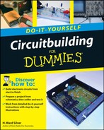
Figure 11-1 shows a basic multimeter of the inexpensive type that many electronicers start with. It may be simple, but has many of the same features of its more expensive and capable siblings. Because it displays its measurement as a numeric value, it is called a digital meter. Analog meters use a swinging needle over a printed scale to display the measured value.
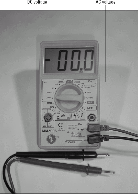
Figure 11-1. This simple multimeter is capable of measuring AC and DC voltage, DC current, and resistance over a wide range of values. Different ranges and quantities are selected by inserting the meter's probes into different jacks and setting the range switch to the appropriate scale.
Tip
In order to measure a wide variety of values, multimeters have a range switch. Electronic circuits involve voltages from thousandths of a volt (millivolts or mV) to hundreds or thousands of volts. Currents can range from the millionths of an amp (microamps or μ) to many amps. Resistances from tenths of an ohm to millions of ohms (megohms or Ω) are common. Trying to measure all of these on a single meter scale would be very difficult, especially for small values. To make the meter easy to read and use in all of the different ranges of values, the sensitivity of the meter is varied. For each range and type of measurement, a different scale is used. The maximum value that can be read in each range is called the full-scale value.
Unless your meter has permanently attached test probes, there will be a set of jacks into which the probe wires are plugged. Which jacks you use determine what measurements the meter can make. The jack labeled COMMON (or COM) is used for all measurements. The black probe is usually the one inserted in the COMMON jack. For permanently attached leads, the black lead always has the same function as COMMON. There may be two voltage jacks; one for sensitive measurements of a few tenths of a volt and one for larger voltages. Some meters also have a high-voltage jack for measuring voltages of more than 500V or so.
To measure current, there must be an input and an output jack. The jack labeled "CURRENT" or "A" is the current input jack, sometimes labeled with a number to indicate maximum current, such as "10A" for a 10-ampere maximum. (Check your meter's manual to determine how your meter is labeled.) COMMON is the current output jack for all current measurements. Reversing the current flow will cause the meter to display a minus sign (-) before the value. Excessive current can damage the meter or blow an internal fuse, requiring you to open the meter and replace it.
Warning
A meter measuring current has a very low resistance between the A and COMMON jacks — almost a short circuit. This can short out a circuit when you think you're going to measure voltage. Double-check before making a measurement!
Tip
Look carefully at the AC and DC voltage labels in the figure of the meter. These international symbols for AC and DC values are used on almost all modern electronic test instruments. The AC symbol is a tilde (~) next to or under the V or A label. The DC symbol is a solid line over a dashed line, indicating that the value is of only one polarity.
Resistance is usually measured using the same jacks as voltage. Some meters use a separate jack labeled "R" or "RES." The meter applies a constant voltage to the test probes and measures current through the unknown resistance, converting the value of current to resistance using Ohm's Law (see Chapter 12). Most analog meters have a single resistance scale calibrated from zero to infinity. The range switch is labeled "×1," "×1000," "×10000," "×1M" or similarly, telling you what to multiply the meter reading by to determine the actual resistance. For example, if the meter needle is pointing to 4.7 and the range switch is set to "×1000," the resistance is 4.7 × 1000 = 4.7 kΩ.
Warning
A meter connected to measure resistance can be damaged if connected to a circuit that has power applied to it. Double-check before making a measurement!
Note
Voltage and current are often measured using different scales for AC and DC. This is done because they are measured in different ways. Be sure to use the right scale! Many simple meters measure only DC current.
The following list shows examples of common ranges and the usual label for the switch. The numeric value of the range may be different, for example 200V instead of 100V.
Voltage: millivolts (mV), volts (V), tens of volts (×10V), hundreds of volts (×100V).
Current: microamps (μA), milliamps (mA), amps (A), tens of amps (×10 A or 10 A). Current range may be automatically selected by using a different jack.
Resistance: ohms (Ω), tens of ohms (×10 Ω), hundreds of ohms (×100 Ω), kilohms (×1000 Ωor kΩ), tens of kilohms (×10000 Ω), megohms (MΩ).
Once the range has been selected, the meter is read by using the corresponding scale on the meter face. For example, when measuring your vehicle's battery voltage you would select the 30V range and read the voltage scale calibrated to show from 0 to 30V.
Warning
Connecting a meter set to its most sensitive range to a circuit with too much current or voltage can damage the meter by pegging the needle past the full-scale point. The desired meter range should be selected with the switch BEFORE the probes are attached to the circuit. If the range isn't known, the least sensitive range is selected and then increased once the probes are attached. Resistance is measured differently so an out-of-range resistance causes too little needle movement instead of too much.
Tip
Many digital meters are auto-ranging meters, a feature that simplifies the process of making measurements. Before displaying a value, the meter itself determines what range of values is appropriate and sets the meter display to the most appropriate scale.
Digital multimeters like those shown in Figure 11-1 perform the very same functions that analog meters do. Digital meters use a microprocessor to convert the measurement to a digital numeric value and show it on an LCD (liquid crystal display). Digital meters can show a measurement value with more precision than an analog meter. The microprocessor automatically calculates the correct range, eliminating the need for a range switch.
The microprocessor can also be put to work making other measurements. Digital meters are available that measure frequency and period, duration, and capacitance and inductance. Some meters can even record the measurements and download them to a computer, using a serial (RS-232) or USB port. Thus you have a simple data logger, as well!
Digital meters can also set the measurement scale automatically; this feature is called auto-range. All you have to do is tell the meter to measure voltage and it does the rest. Some meters can measure a value continuously and show the maximum or minimum values, a feature called peak hold. AC voltage and current measurements can also depend on the shape of the signal's waveform. A meter with true-RMS measurement capability is insensitive to the signal's shape.
DC voltage is a pretty straightforward concept: The voltage has a magnitude and a polarity. AC voltage is not so straightforward; the continuous reversals of alternating current mean that the magnitude at any particular time (called the instantaneous voltage) is always changing. The waveform has positive peaks and negative peaks and zero-crossings — where the instantaneous voltage is zero — twice per cycle! So when we talk about AC voltage, what do we mean? As it turns out there are four ways of talking about AC voltage, all shown in Figure 11-2:
Instantaneous voltage: The voltage at any particular instant in time, abbreviated VINSTor just lowercase v.
Peak voltage: The maximum value of VINSTin any single cycle with positive and negative peaks assumed to be the same. It's abbreviated VPK.
Peak-to-peak voltage: The voltage between the positive peak and negative peak in any single cycle, abbreviated VPK-PK or VP-P.
Root-mean-square or RMS voltage: The value of a DC voltage that would deliver the same amount of power to a load as the AC voltage, abbreviated VRMS.
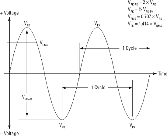
Figure 11-2. There are several different ways to describe the voltage of an AC waveform. Conversion factors allow you to convert one type of measurement to another for a given waveform, such as the sine wave shown here.
We were doing really well up until RMS voltage! Where did that come from? In the early days of electrical power, some utilities supplied DC voltage (Edison's utility was in this group) and others supplied AC voltage (Tesla's backers, Westinghouse, were in this group). Suppliers of ovens, furnaces, or motors needed a way to tell their customers how much power their products would consume or produce — on both DC and AC systems. Engineers determined that the RMS voltage of an AC waveform was equivalent to a DC voltage of the same value when it came to figuring out how hot a heating element would get or how hard a motor would work. In other words, if the RMS voltage of an AC waveform was the same as a DC voltage, both would do the same amount of work.
I'll not get into the gory details of the equation to determine the RMS value of a waveform. Suffice to say that for sine waves, the RMS voltage is 0.707 × VPK. When the power company tells you that line voltage is 120V, that is the RMS value. The peak voltage is higher; VPK= 1.414 × VRMS. For 120 VRMSAC, VPK= 120 × 1.414 = 169.7V. The RMS-to-Peak conversions are different for other waveforms, but those are rarely needed.
This is important to voltage measurements because you need to know whether your meter displays voltage as RMS, peak, or peak-to-peak. Most multimeters read RMS by assuming the AC waveform is a sine wave and printing the corresponding scale on the meter's face, or by doing simple math in the meter's microprocessor. A multimeter that measures true RMS actually uses its internal microprocessor to perform the full calculation for any waveform. Check the manual for your meter to find out which type of AC measurement it performs.
A power supply used for building and testing circuits has to be a bit more flexible than one intended for running a radio or charging a battery. Those supplies generate power at a single DC voltage that cannot be adjusted. Circuitbuilding requires a power supply with these features:
Adjustable output voltage: A range of at least 3 to 15V.
Bipolar voltages: Both negative and positive voltages with a common ground.
Meters for current and voltage: Display the supply outputs.
Current: 0.5 amps or more.
Voltage tracking: The capability to match both positive and negative output voltages (for example, - (12V, (15V, (6V, and so on) is nice to have but not required.
Current limiting: The capability to restrict the amount of current the supply outputs; this feature is also nice to have.
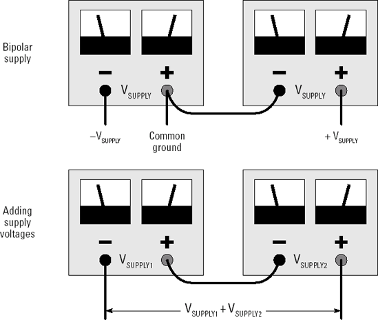
The supply in Figure 11-3 is a typical lab supply. These are available both as new and used equipment in a wide variety of sizes and power capacities. This is a dual supply with two independent or floating power supplies in the same enclosure. A meter reads the voltage and current being delivered by each supply. The terminal labeled with the ground symbol is connected to the metal enclosure or chassis of the supply. It can be connected to either of the power supply outputs, if need be.
Figure 11-3. A dual lab supply has two internal power supplies, completely isolated from each other and usable independently or combined.
Tip
The outputs of floating supplies (ONLY floating supplies can be used this way) can be combined by connecting the positive terminal of one supply to the negative terminal of the other, as shown in Figure 11-4. Connected together, the terminals can act as the common ground terminal of a bipolar supply, with one supply providing positive voltage and the other negative. By not connecting the common terminals to anything and taking the output from the remaining terminals, a higher voltage output than is possible from either supply because the voltages add together. Both supplies are still subject to the current limits of either supply. At high currents of several amps or more, it's best to use a single power supply.
You can use fixed-voltage supplies and even battery packs to power your circuits with the loss of flexibility and metering. With a little ingenuity, your circuits will never know! For example, a battery pack with several cells connected end-to-end can provide a different voltage from each cell; an inexpensive multimeter can act as the supply meter.
What on Earth is a function generator? This oddly-named device generates functions, of course! (That helps, right?) Seriously, a function generator produces AC signals of various useful types — usually sine waves, square waves, and sawtooth or ramp waves.
Note
Function refers to the type of wave (or waveform) and is a term from the early days of analog computing when equations were solved by wiring up a circuit that simulated the problem. Figure 11-5 shows the difference between the different functions. The frequency and amplitude of the output signals is adjustable; from below 1 Hz to many tens of kHz — and from millivolt levels to several volts. Function generators are used to produce test signals for circuits.
Function generators are widely available as kits as well as at any store selling used and new equipment. If you're a beginning builder, a function generator in kit form — such as the Electronic Kits FG-500 (www.electronickits.com/kit/complete/meas/fg500k.htm) or Vectronics VEC-4001K (vectronics.com/products.php) — would be a good way to learn more about building (see Part II for information about building kits) and make a useful instrument you'll be able to use for years and years.
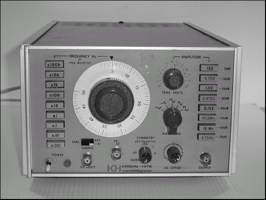
Figure 11-5. Function generators produce waveforms used in testing and developing circuits. The frequency and amplitude of the output are continuously adjustable over a wide range.
When shopping for a function generator, here are some of the features you should look for:
Types of waveforms: Sine and square waves are a must; triangle and sawtooth are nice to have.
Waveform amplitude: Adjustable from 10 mVPK-PK (or smaller) to 5 VPK-PK (or larger) is a good range. Somewhat less range is okay at either end of the scale.
Balanced or floating output: As with the floating power supply, the generator's output is not connected to ground; this is handy occasionally but not necessary.
Waveform adjustments: These are adjustments to the wave's shape; all are nice-to-haves, but not necessary:
DC offset: Adds a DC voltage to the output.
Symmetry: Make a square, triangle, or sawtooth waveform asymmetric.
Trigger: Generates output signal only after receiving a signal from an external circuit or device.
Sync or logic-level output: A square-wave signal that is the same frequency as the output waveform, used for synchronizing measurements with other equipment or as an input signal to digital logic circuits.
Sweep: The ability to automatically change the output frequency through a settable range.
Digital frequency display: Compared to a mechanical dial, it's nice to have.
While you can get a whole lot done with the simple equipment mentioned in the preceding section, this section lists a few more instruments that can make life at the workbench a lot simpler. I advise that you get some experience with the simple equipment before jumping into the advanced list. You'll find that your specialty or interests in circuits leads you more naturally to certain kinds of test equipment.
The companion to a function generator is the counter. These instruments are actually not frequently used for counting. Instead, they measure a signal's frequency — counting the number of events or cycles in a certain period of time, and then calculating a frequency, just as a nurse would take your pulse in heartbeats-per-minute by counting your pulse for 15 seconds and multiplying by four. A typical portable counter is shown in Figure 11-6.
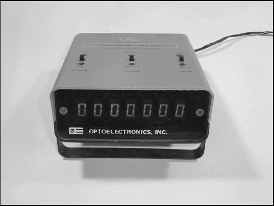
Figure 11-6. A basic counter used for field and bench measurements. Designed for use with radio signals, this counter shows frequencies as high as 500 MHz.
You'll need a counter if you need to know frequency of a signal or its period fairly precisely. Here are some examples of circuitry for which a counter would be useful:
Tachometers
Oscillators
Speedometers
Switching-type power supplies
Each of these circuits has as its input or output a sine wave, square wave, or sequence of pulses whose frequency carries information or is important in some way. You can use an oscilloscope to measure frequency as we discuss later, but for most frequency measurements a counter is much more convenient.
A basic counter should have these features:
Counts frequency over the frequency range you're using
Displays frequency, period (the inverse of frequency), or total (a count of cycles or events)
Accepts signals of the type you're measuring, such as sine wave or pulses
Accepts signals of the amplitude you're measuring, especially weak or low-voltage signals
A multimeter can check resistors just fine, but what about capacitors, inductors, diodes, and transistors? Even if you know the component type or its nominal value (the labeled value), it's often necessary to test the value or to see if the component is functioning. Dedicated component testers are a worthwhile addition to your growing stable of equipment if you do a lot of building or troubleshooting.
Capacitor tester: Measures capacitor value and leakage (the amount of DC current allowed between the terminals).
Inductor tester: Measures the inductor value.
Transistor tester: Determines whether the transistor is NPN, PNP, JFET, MOSFET and measures its current or voltage gain.
Tip
Many midrange digital multimeters have component test features built in. They can read the value of capacitors and inductors, plus check whether transistors are good and measure their current gain, or beta.
If you build a lot of digital circuits, a logic probe such as the Webtronics LP-1 (webtronics.stores.yahoo.net/lp-1.html) is very handy. It's a special type of multimeter, made to read the 1s and 0s of a digital circuit and display them as the color of an LED. A logic probe has clip attached to the circuit's ground; you touch the probe's tip to the circuit being tested. The LED indicates the logic level, including open circuits and active circuits switching between 1 and 0, such as an address or data bus. The fancier models can also read voltage and frequency.
This section could be a whole book by itself because there is a lot of specialized equipment for signals beyond the audio range. Special measurement techniques are required for precise measurement, too. Nevertheless, if you're just interested in checking your CB or handheld radio, a scanner, or a shortwave receiver, it's not necessary to have an engineering lab full of equipment. The following items are handy and won't break the bank:
Standing Wave Ratio (SWR) meter: Measures the output power of the transmitter and whether the power is being accepted by the antenna. For an example of how to use an SWR meter with a CB radio, see
www.firestik.com/Tech_Docs/Setting_SWR.htm.Signal generator: Works like a function generator, but outputs only sine waves and at much higher frequencies.
Dummy load: Used when testing transmitters, dissipating the output power to avoid putting an interfering signal on the air.
Antenna analyzer: Tests antennas and feed lines over wide frequency ranges.
Cable tester: Checks cables to be used with radios and antennas for opens and shorts, as well as the amount of signal loss.
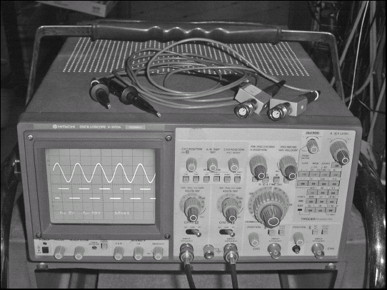
The oscilloscope serves as the electronic eyes of an electronic-er, presenting visually what a signal looks like electronically. An oscilloscope (or just scope to those in the know) speaks volumes more about a signal than a multimeter or counter. It can also display signals at frequencies far beyond what a multimeter can handle. Learning to use a scope will take you to the big leagues of circuitbuilding!
A scope's basic function is to display the amplitude of a signal versus time. Figure 11-7 shows a scope displaying a sine wave with a frequency of 100 kHz and an amplitude of 2 VPK-PK. The signal's voltage is measured against the vertical scale and the duration of each cycle is measured on the horizontal scale. The rectangular grid on the scope's display is the graticle. In this case the vertical scale is 1V per rectangular division (written as 1V/div) and the horizontal scale is 5 μsec per division (written as 5 μs/div).
Note
Graticle: The graticle of an oscilloscope is a rectangular grid of lines that makes the surface of the display look like graph paper. The graticle is divided into vertical and horizontal divisions. Depending on the sensitivity and sweep speed settings of the oscilloscope, each division can be made to represent different values of voltage or time. In that way, waveform amplitude and frequency measurements can be made.
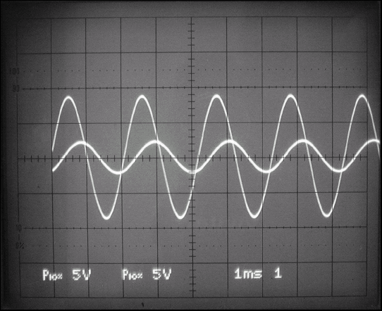
The horizontal scale is determined by the scope's sweep speed. The way this type of scope displays a signal is to move a beam of electrons across the face of the display tube behind the graticle, causing a phosphor coating to glow as seen in Figure 11-8. The faster the beam moves, the less time it takes to cross each division. To display higher frequency signals, the beam must move faster and the time per division will be lower. For example, to display a 1MHz signal instead of a 100kHz signal (10 times higher in frequency), the sweep speed would have to be increased from 5 μs/div to 0.5 μs/div (or 500 nsec/div). That signal would also take 2 horizontal divisions to complete one cycle as the beam moves across the tube. Adjustments to the sweep speed allow you to zoom in or zoom out to view different characteristics of the signal's behavior in time.
The vertical scale is determined by how much the signal is amplified by the scope's vertical amplifier. If the gain of the vertical amplifier is increased, the signal appears larger in the vertical direction. For example, if the vertical gain in Figure 11-8 was increased by a factor of 2, the signal would be 8 divisions high instead of 4 and the vertical scale would be 0.5V/div instead of 1V/div. Many scopes have more than one input, each with its own vertical amplifier. Each input and vertical amplifier is called a channel. These scopes can display more than one signal at a time and at different vertical scales. Both signals share the same horizontal scale; you can compare the two different signals in detail. For example, the input and output of a filter circuit are shown in Figure 11-8 showing the different voltage levels and the delay between input and output. This is where the true power of the oscilloscope lies.
The circuits in the scope that cause the electron beam to start sweeping across the display are called the trigger circuits. These circuits can be configured to let the beam sweep continuously, only when the signal is larger than some threshold, or just once and stop. Trigger circuits can also synchronize the electron beam to a video signal (the "TV-V" and "TV-H" settings) or to the AC power line ("Line" setting), if that helps make the displayed signal easier to see. For example, if you're trying to troubleshoot an annoying case of AC hum in a microphone amplifier, using the line trigger setting would help you see hum signals that are caused by pickup from the AC line.
Special probes are used to connect the oscilloscope inputs to actual circuits. The vertical amplifiers are very sensitive to avoid loading the circuit being tested. Loading occurs when a test probe or another circuit siphons off enough current to affect the circuit's operation. The most common type of probe is a ×10 (pronounced "times 10") probe. This probe reduces a signal's amplitude by a factor of 10 when connected to a scope's input. This is a result of reducing the scope's loading of the circuit. The scope's calibration and scales account for this reduction, so if you connect the circuit directly to the scope without a probe, it will appear to be 10 times bigger than it really is.
Note
Be sure to use probes with a scope so your measurements will be accurate.
There are two kinds of oscilloscopes; analog and digital. Figures 11-7 and 11-8 show an analog scope. Analog scopes move an actual electron beam back and forth; they are the original and oldest type of scope. A digital scope converts the input signal to digital data and then displays it on a small computer screen — in the same form as an analog scope. Digital scopes are designed to look and function like analog scopes because circuit designers are so used to that look and feel.
The advantage of a digital scope is that the data, being digital, can be downloaded to a PC, including a screenshot of the display. A digital scope can also make automatic measurements of voltage, frequency, period, and so forth, displaying them directly on the screen. Those measurements must be made manually on an analog scope. Digital scopes also do away with the heavy and bulky display tubes of analog scopes. Nevertheless, the greater complexity of the circuitry in a digital scope drives its cost up to somewhat more than an analog scope with the same performance levels.
A complete description of how to measure signals with an oscilloscope is well beyond the scope of this book. There are, however, several excellent online tutorials such as the following:
Colin McCord's "Using An Oscilloscope" at
www.mccord.plus.com/Radio/oscilloscope.htmHobby Project's Oscilloscope Tutorial at
www.hobbyprojects.com/oscilloscope_tutorial.html
If you purchase an oscilloscope, the manufacturer probably includes tutorial material with the instrument or on its Web site. I highly recommend working through the tutorials in detail before using the scope to measure your circuits.
Voltage is measured by displaying the signal and counting the number of vertical divisions between the points you wish to measure. If the signal occupies 5.3 vertical divisions and the vertical scale is 500 mV/div (the same as 0.5V/div), the voltage measurement is 5.3 × 0.5 = 2.65V. Note that the center of the graticle has extra markings to help make sub-division measurements.
Tip
Scopes have a Horizontal Position control that allow you to shift a signal back and forth on the display. Use this control to position the signal over the finer vertical scale in the center of the graticle.
Current is not directly measured by a scope and must be converted to a voltage first. A special current probe is used to measure current more directly. The current probe is placed over the wire carrying the current to be measured and the current's magnetic field is converted into a voltage by the probe. Current probes are fairly expensive; they're not often used in the home electronics shop.
Time is measured by displaying the signal and counting the number of horizontal divisions between the points you wish to measure. If the signal repeats every 8.3 horizontal divisions and the horizontal scale is 2 ms/div, the period between signals is 8.3 × 2 = 16.6 ms. The frequency of a signal is the inverse of its period, so this signal has a frequency of 1/16.6 ms = 60 Hz. This signal would be a good candidate for the use of AC-line display triggering.
Logic analyzers are scopes designed for use exclusively with digital logic signals. Signals are not displayed in terms of their voltage, but rather in terms of their logic value: 0 or 1, high or low. A logic analyzer also has many channels, typically 8 to 16 at a minimum. Its test probes are connected to the analyzer as one large cable, terminating in a module with multiple thin clip leads for testing; these connect to the circuit you're testing. A logic analyzer is used to look for proper and improper operation of digital circuits, showing how the signals change at different times.
Instead of showing time on the horizontal scale, spectrum analyzers show frequency. A spectrum analyzer is really a special type of receiver. It sweeps a narrow filter across a range of frequencies, displaying the amplitude of the filter's output on the vertical scale and the filter's frequency on the horizontal scale. It's as if you rapidly tuned a radio across the band, making quick measurements of the strength of each signal. Spectrum analyzers are very, very useful to RF circuit designers and are used from audio frequencies up to many gigahertz.