Chapter 11 looks at several different kinds of test instruments used in electronics; this chapter puts those instruments to work, assuming only that you have the basic equipment: multimeter, power supply, and function generator. The tasks in this chapter are short experiments designed to familiarize you with each technique. You'll then be ready to use your test equipment in the many ways that circuitbuilding requires.
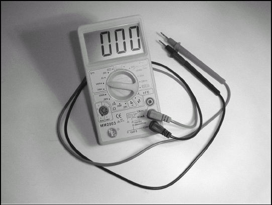
The multimeter used in this chapter is assumed to be an inexpensive digital multimeter. These are widely available and are the usual first choice of experimenters and circuitbuilders like you. If you have a fancier model, the procedures will be the same. If you have an analog multimeter (the kind that uses a moving needle), you won't be able to read the numbers directly, but the measurements are similar. Spend some time with the operating manual for either type of meter to be sure you're familiar with its controls before beginning.
All these tasks except measuring period and frequency can be performed with advanced equipment, such as the oscilloscope. Regardless of whether you're using the basic or the advanced equipment, the stuff between your ears is the most important test instrument of all!
Maybe this could have been a Part of Tens chapter in the back of the book — but you need to see and consider these warnings now! Making measurements of voltage or current are done on live circuits. Although most operate from less than 30 volts with minimal hazards from shock, there may still be significant sources of energy that deserve respect and caution. This section points out ten basic safety precautions that you should learn to follow as a habit, regardless of the type of circuit:
Electricity moves a LOT faster than you can. Don't ever think you can outrun it by swiping a finger across a terminal to see if it's hot. If it is, there's no difference between your finger contacting the electricity for 1/10th of a second or 10 seconds. The electricity will flow in nanoseconds! Use a meter or tester to make the check.
Don't give electricity a path through your body. The most dangerous shocks occur when current flows through the chest, such as from arm to arm. Arm to leg shocks can also be dangerous. Start by not touching live conductors in the first place! Next, keep one hand in your pocket while making a measurement, if possible. Never work barefoot or in wet places or on a wet workbench.
If the equipment you're working on is powered from AC line voltage, consider using an isolation transformer. Isolation transformers transfer power from the wall socket to your equipment, but without a direct connection to the AC line. The equipment is still live, but there won't be any direct connection to either the AC wiring hot or neutral wires.
Use a circuit protected by a GFCI (Ground-Fault Circuit Interrupter) circuit breaker. A GFCI breaker can remove power from a circuit very quickly if there is an accidental short-circuit or shock hazard. This protects you when the electronics is exposed and you're making measurements. You can install a GFCI outlet for your workbench.
Don't use frayed or worn probes, cables, cords, connectors, or clip leads. All it takes for a shock is one tiny strand of wire poking through some insulation or out of a connector. Whenever you use them, inspect them, repairing or replacing whenever necessary. Should you encounter a truly old AC line cord with cotton or rubber insulation, discard it immediately and do not try to salvage it.
Batteries as small as an AA cell can deliver enough current to melt insulation and start a fire under the right conditions. Imagine what can happen when wiring connected to a car battery develops a short circuit or a metal tool falls across the battery's terminals! Whenever working around batteries of any size, make sure an accidental short will not blow a fuse and remove power. When working on a car's electrical system, disconnect one terminal of the battery completely.
Safety interlocks and lockouts exist for good reasons and not just to satisfy over-zealous safety regulators. Interlocks prevent you from encountering high voltages, powerful RF fields, dangerous levels of heat, and other hazards inside equipment. Never bypass an interlock unless you're expressly instructed to do so by a manufacturer's instructions. Never leave an interlock bypassed when equipment is reassembled. If working on line-powered equipment, tag and lock out the circuit breakers so someone else doesn't accidentally turn the equipment on just as you start your repairs!
High-power radios and antennas can generate enough RF energy to cause heating of your skin and body. The immediate effect is a burning sensation. Long-term exposure to high levels of RF energy in some frequency ranges can lead to a variety of health problems. For more information about exposure to RF, check out
www.arrl.org/tis/info/rfexpose.html. Be wary of working around high-gain antennas operating above 20 MHz. If you're working on a powerful radio, consider removing all metal jewelry, particularly from your hands, since it can pick up the energy and heat or arc to your skin.Motors and wheels and gearboxes in medium and large robots can be dangerous to the operator — that's you! Loose clothing, ties, bandanas, long hair, or even work gloves can all be caught by a spinning shaft in an instant, especially during testing and checkout procedures. (The author has personally experienced such a scary event.) Dress properly and with respect for what a powered-up electro-mechanical system can do.
If you're working on equipment that presents a credible safety hazard, such as high voltage, make sure someone else is around to check on you. They should also know how to remove power from your workbench outlets and perform basic first aid. CPR training would not be a bad thing for you and your friend to learn. These suggestions are not solely for electronics — they apply to any kind of workshop use.
Last, but not least, don't goof around in the shop or at your bench. Although it may be funny to clap your hands together behind someone just about to touch a probe to a circuit, if by reacting they are shocked or damage the circuit it will quickly cease to be amusing. If you snack or sip while working (and who doesn't?), make sure the crumbs and spills can't get into your equipment or circuits.
A multimeter measures resistance by using Ohm's Law. The meter doesn't measure resistance directly, it measures current which it then converts to a resistance reading. Here's how:
Inside the meter is a battery and a circuit that creates a constant output voltage from the battery, about 1 V or so.
When the meter is set to measure resistance, it applies that voltage to the test probes.
The test probes connect to the component or circuit being tested.
Using Ohm's Law, the current through the probes must be I = E / R. E is the constant output voltage from the meter.
By measuring the current and converting it to ohms, the meter indirectly measures resistance. As long as the test voltage is constant, this method works just fine. If the internal battery weakens and can't generate enough voltage, the meter can no longer measure resistance properly.
Another technique is to use a constant current instead of voltage. The current flowing through the resistor creates a voltage according to E = I × R. The meter converts the voltage to resistance and displays the result.
You can use Ohm's Law in just the same way when testing a circuit. For example, if you want to know how much current is flowing through a resistor, but it's not convenient to disconnect the resistor to use the meter, measure voltage across the resistor instead. Then use the equation I = E / R to calculate what the current is.
There's no place like Ohm — Ohm's Law
If you want to understand the foundation of circuits, Ohm's Law is one of the cornerstones. Georg Ohm was a German scientist that discovered the exact nature of the relationship between voltage and current in the early 1800s. With the study of electricity in its infancy, this was a major breakthrough!
Ohm found that current was directly proportional to voltage and that the constant of proportionality was a quantity he called resistance. All materials seemed to exhibit resistance and the amount of resistance varied with the type of material. Ohm stated this relationship between voltage, current, and resistance as a mathematical equation:
(a) R = E / I
With a pinch of algebra, this equation can take two other forms:
(b) E = I × R
(c) I = E / R
These equations "say" very simple things.
(a) says that resistance is directly proportional to voltage given a fixed current (resistance increases as voltage increases) and inversely proportional to current given a fixed voltage (resistance decreases as current increases).
(b) says that the voltage across a resistance is directly proportional to the current through the resistance.
(c) says that current through material is directly proportional to the voltage across the material and inversely proportional to the material's resistance. They're all describing exactly the same relationship from differing points of view.
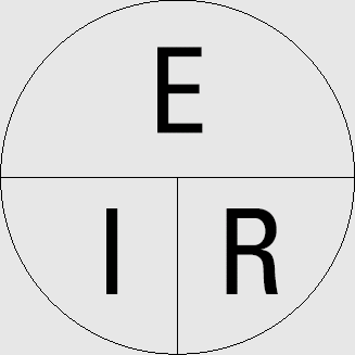
See the figure in this sidebar to help you remember Ohm's Law (and you should — you'll use it often). If you know any two of voltage, current, or resistance, you can find the other. Cover the unknown quantity and the figure shows you whether to multiply or divide them. For example, if you know voltage and resistance, cover the wedge labeled "I" and the two remaining wedges, E above R, show that you should divide E by R.
Tip
Remember these two handy sentences and you'll save yourself a lot of calculator keystrokes:
Megohms × microamps = volts
Kilohms × milliamps = volts
Both of these shortcut time-savers can be used in many common circuits.
In the tasks that follow, we'll use all three forms of Ohm's Law to ferret out the unknown value from using the two known quantities. Ready, Mr. Holmes?
Repairing equipment and building circuits often requires testing a transistor. Is it still OK after that overload? The circuit's not working at all, but is the transistor good? Is this diode marked properly? In the "Checking a Transistor" task later in this chapter, you'll learn how to make basic checks on diodes and four common types of transistors, using only a multimeter.
Inspect your meter and determine whether it has a diode-checking function. Many digital meters do. This is usually labeled on the range switch with a diode symbol. If not, resistance measurements will be used with the meter scale set to ×1000 or a full-scale reading of 1 or 2 kΩ.
A meter with the diode-checking function tries to push a few mA of current through whatever the test probes are connected to, displaying the resulting voltage. When the test current flows through a silicon diode junction, such as is found in diodes and rectifiers and bipolar transistors, the resulting voltage drop represents the forward voltage of the junction. (For more information on silicon diode and transistor junctions, see the Wikipedia entry at http://en.wikipedia.org/wiki/Pn_junction.) Typical forward voltages are 0.6 - 0.75V at the current levels used by meters. The meters can also test two or three diodes in series, adding together the voltages across each junction. Check the manual of your meter to determine precisely what it can do.
Tip
Many digital meters can measure a transistor's current gain (also known as beta or hFE). If you plan on doing a lot of circuitbuilding, this feature is often worth searching for. Keep on the lookout at flea markets or on the Web for used multimeters or kits for building transistor checkers that have actual sockets for transistor and diode leads.
Analog meters rarely have the diode-checking function, but you can still perform checks by using the meter's resistance test circuits. As you learned in the task "Using Ohm's Law", resistance can be measured by applying voltage to an unknown resistance and measuring the resulting current. When the unknown resistance is actually a silicon diode or transistor junction, the resulting current is about the same as for a 1 kΩresistor.
Since diode and transistor junctions only conduct in one direction — from the P-type material to the N-type material — the probes must be applied to push current in that direction and the meters display results as described earlier in this section. These are called "forward tests." In the reverse direction, the multimeters will show an open circuit and these are called "reverse tests."
What if the transistor is defective or has been damaged? Junctions that are open where the tables indicate current should flow indicate a blown transistor. Transistors and diodes also sometimes fail with a short circuit and that is seen as abnormally low voltages or resistances in both directions. As you test more transistors and diodes, you'll develop a sense of what is a normal reading and what is abnormal.
As you gain experience with circuits and electronics, you'll discover that many measurements are made in decibels. What are these decibels and what kind of value are they? A complete discussion of decibels is beyond the scope of this book, but you can find out a lot more at the Wikipedia entry on decibels at en.wikipedia.org/wiki/Decibel.
The most important thing to learn (and remember!) about decibels (or dB) is that they are a ratio, not a unit of measure. Decibels have no units! They are a ratio of two values that both have the same units. Decibels are also logarithmic so very large ratios can be expressed in much smaller numbers as dB. You can calculate decibels as ratios of power or of voltage (or current). Here are the formulas for calculating dB where log is the base-10 logarithm:
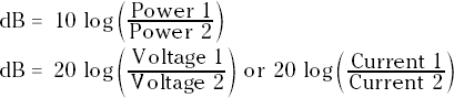
Speaking in terms of power, a change of 10 dB is the same as a 10× change in power. Table 12-1 shows numeric and decibel ratios. If you're using voltage or current instead of power, use the second equation shown here.
Table 12-1. Numeric Ratios vs Logarithmic Ratios
Numeric Ratio (P1/P2) | Logarithmic Ratio = log (P1/P2) | Decibels = 10 log (P1/P2) |
|---|---|---|
1 | 0 | 0 |
2 | 0.3 | 3 |
4 | 0.6 | 6 |
5 | 0.7 | 7 |
8 | 0.9 | 9 |
10 | 1.0 | 10 |
20 | 1.3 | 13 |
40 | 1.6 | 16 |
50 | 1.7 | 17 |
80 | 1.9 | 19 |
100 | 2.0 | 20 |
1000 | 3.0 | 30 |
10000 | 4.0 | 40 |
0.5 | −0.3 | −3 |
0.25 | −0.6 | −6 |
0.2 | −0.7 | −7 |
0.125 | −0.9 | −9 |
0.1 | −1.0 | −10 |
0.05 | −1.3 | −13 |
0.025 | −1.60 | −16 |
0.02 | −1.7 | −17 |
0.0125 | −1.9 | −19 |
0.01 | −2.0 | −20 |
0.001 | −3.0 | −30 |
0.0001 | −4.0 | −40 |
To reiterate, decibels represent quantities that are ratios of gain, loss, rejection, attenuation, and so on. Negative decibels represent a ratio less than one. If a letter follows dB, such as dBm, dbV, or dBW, that tells you what Power 2 or Voltage 2 is in the equations discussed earlier in this section.
dBm means decibels with respect to 1 milliwatt (Power 2 = 1mW)
dBV means decibels with respect to 1 volt (Voltage 2 = 1V)
dBW means decibels with respect to 1 watt (Power 2 = 1W)
By using a specific reference power or voltage, decibels represent a specific power or voltage. For example, 10 dBm means 10 decibels greater than 1 mW or 10 mW. −20 dBV means 20 decibels less than 1V or .01V. 3 dBW means 3 dB greater than 1 watt or 2 watts. Without that letter designating a reference, decibels are ratios only without units.
What could be simpler? Set the multimeter to VOLTS and touch the probes to the points between which you need to know the voltage! It's not quite that simple, but in this task you'll make a few measurements and pick up a few tips.
Inspect your meter and set it to measure DC voltage, connecting the test probes with the black probe in the COMMON or - jack. Set the range switch to the smallest scale with a full-scale voltage of 2V or higher. For example, if the meter has full-scale voltages of 2V, 20V, and 200V, use the 2V scale (sometimes labeled '2000m' for 2000 mV).
Tip
The so-called 1.5-volt battery may not be anywhere close to 1.5 volts. Rechargeable battery voltages will measure closer to 1.2 - 1.3V, depending on battery type (NiCad, LiMH, Li-Ion, and so on) or the battery's "chemistry." Alkaline cells and good old carbon-zinc batteries are the closest to 1.5V.
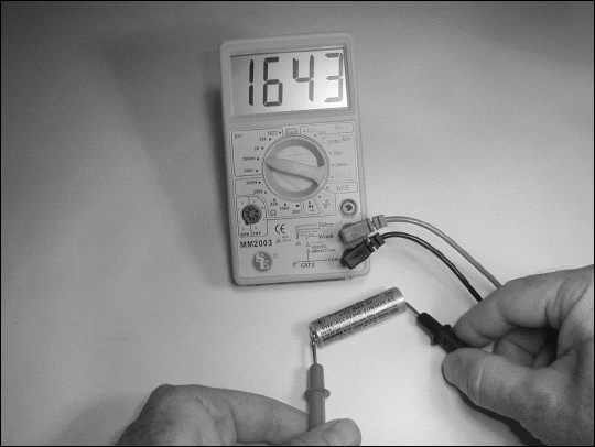
Place the tips of the probes on the terminals of a 1.5V battery. Determine which terminal is the positive terminal by using the multimeter. When the multimeter shows a positive value (the needles of the analog meters will move up the scale across the meter), the COMMON probe will be on the battery's negative terminal.
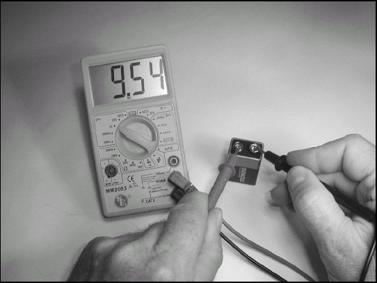
Switch the meter to measure 9V, changing the scale, if necessary. Connect the probes to the 9V battery and see which of its terminals is positive. (From here on, you're responsible for changing your meter to the appropriate scale for each step.)
Measuring battery voltage when the battery is not connected to anything gives you the open-terminal voltage. When the battery is powering a circuit or device, its voltage will drop, much as a motor's speed drops when a load is applied. Install one of your batteries in a radio or music player and measure the voltage with the device OFF and then with the device ON to see the battery voltage change.
Tip
A 9V battery is made up of 6 small internal battery cells hooked up end to end so their voltages add together. (This is called a series connection.) Depending on the chemistry used in the cells, the sum may be anywhere from 7.2 to 9 volts.
Return to the 9V battery and measure its voltage. Switch the meter between reading AC and DC voltage. Does the meter reading change? Some meters will only read the AC value of any voltage, even if there is plenty of DC voltage present. These meters will read 0V for the AC measurement (or a very small value) and the battery's open-terminal voltage for the DC measurement. Other meters that can measure RMS (see the sidebar "When Is a Volt Not a Volt?" in Chapter 11) will measure the same value for battery voltage for both AC and DC. Check your meter's manual for a complete discussion of what the meter actually measures.
Turn on your function generator and set it to output a sine wave of 1V RMS at a frequency of 1000 Hz (1 kHz). If the function generator has DC offset capability, turn it OFF. With your multimeter set to measure AC voltage, measure the output of the generator. If the generator has a coaxial connector, such as a BNC (see Chapter 8 for information on this type of connector), connect the black probe to the connector shell and the red lead to the center contact.
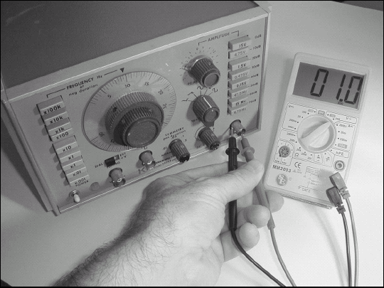
Change the meter to measure DC voltage. What happened to the reading? This waveform has no DC component, so the meter will show 0V. (If your generator has DC offset capability, turn it back on, vary the DC offset voltage and observe what happens on your multimeter.)
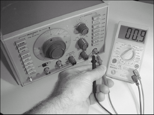
Set the meter to measure AC voltage and turn off the generator's DC offset. The generator is back to producing a 1 kHz sine wave. Measure the AC voltage at the generator's output. Without changing the output voltage, switch the generator between sine, square, and triangle or sawtooth waveforms, watching the voltage reading on the meter. Waveform shape makes a difference in how your meter measures AC voltage as described in Chapter 11.
Note
Components: A voltage can have both AC and DC characteristics, called components. For example, a power supply may output 12V DC, but with small AC variations around 12V called ripple.
Return the generator's waveform to a sine wave. Check the meter's ability to measure AC voltages at higher frequencies by increasing the generator's frequency until the AC measurement begins to fall. Where the meter's reading drops by more than a few percent is the upper limit of frequencies at which the meter's reading is correct. Readings at higher frequencies will be lower still, causing the meter to read erroneously low values.
If you constructed any of the circuits in Part II or have other projects lying around, take this opportunity to exercise your newfound measurement skills. With the stereo pumping out some music, measure the voltage at the speaker terminals. What is the output voltage from your collection of "wall wart" power supplies that plug into the wall socket? (Be sure to measure both the AC and DC components!) Measure the voltage on your car's battery with the engine off and with the engine running.
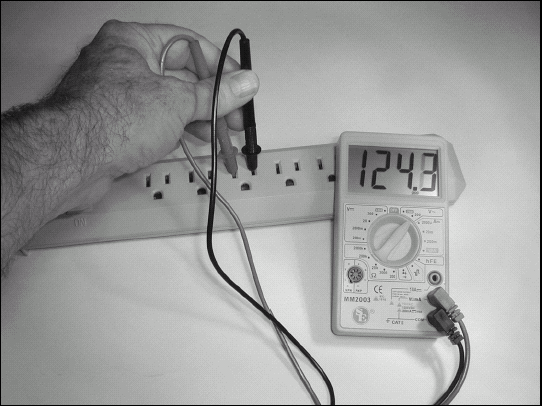
Now for the main event! A drum roll, please ... measuring AC voltage directly from a wall socket! This is completely safe if your test probes are in good condition as discussed in the safety list at the beginning of this chapter and you have the meter set to the right range for measuring 115V AC. After checking both of those things, approach the wall socket. Keeping your fingers well away from the test probe's metal tips or clips, stick the black probe into one of the plug slots (it doesn't matter which). Now stick the red probe into the other slot. Your meter will now read somewhere between 100 and 130V AC, depending on how the power company is doing that day. Remove the probes from the slots and mop the sweat from your brow. Good work!
Measuring current is a lot like measuring voltage except that the current must be routed through the meter. You must make the same considerations for AC and DC currents; moving the test probes between jacks and changing the meter's range switch to the proper position. Current flows into the meter through the jack labeled "Current." Current flows out of the meter through jack labeled "COMMON" or -.
In this task, you'll measure current flowing in a light bulb, powering a music player, and in a simulated speaker. These measurements are typical of those you'll perform as part of building circuits and you'll gain experience in setting up your meter to measure current.
Whenever changing a multimeter between measuring voltage and current, be sure to insert the test probes into the correct jacks. The resistance through the meter when measuring current is very small, so having the test probes in the current jacks when you connect them to measure voltage can short out the circuit you're testing. This may blow a fuse inside the meter or damage your circuit, so be careful!
Inspect your meter and set it to measure current. If there is a choice, select DC current. Insert the test probes into the current output (COMMON or -) and current input jacks. If your meter has different jacks for different ranges of current, use the jacks for currents of approximately 200 mA.
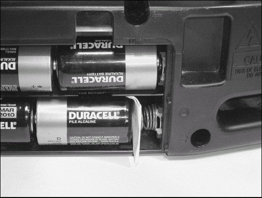
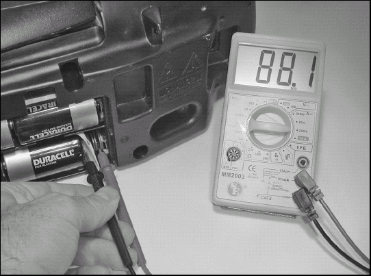
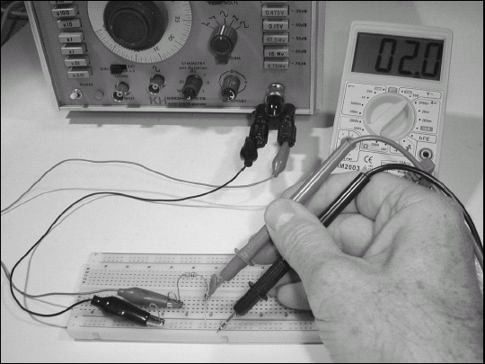
Turn the radio or music player OFF and open the battery compartment. Push the battery away from the battery holder contact and slip in the strip of paper as shown in the figure. This opens the circuit between the batteries and the internal electronics.
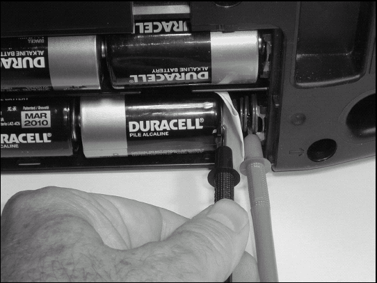
Connect one of the meter's probes to the battery holder contact on one side of the paper strip, using a clip lead if necessary, or just slipping the probe into the spring as shown in the figure. Slip the other probe between the paper strip and battery terminal.
With a speaker or headphones attached, turn the radio or music player ON, tune in a station or play a song and observe the meter. If your meter has more than one current scale, select the smallest scale whose maximum value is larger than the displayed current. For example, if the current is 25 mA and the current scales on the meter are 2000 mA (2 A) and 200 mA, use the 200 mA scale.
Turn the volume up and down to see what happens to the current being drawn from the batteries. If you can switch the player between a speaker and headphones, see which draws the most current from the batteries.
If you're unfamiliar with Ohm's Law, please start this task by reading the sidebar, "There's No Place Like Ohm — Ohm's Law" earlier in this chapter. Whether you design your own circuits or not, understanding Ohm's Law is an important part of electronics testing and troubleshooting.
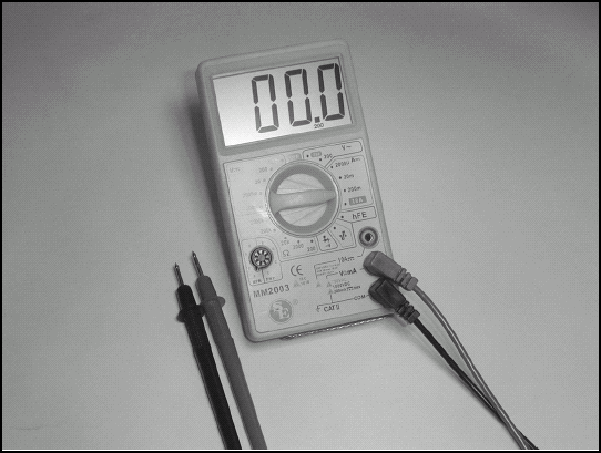
Inspect your meter and set it to measure resistance. Select the full-scale range closest to, but greater than 1 kΩ. With the probes separated, your meter should indicate an open circuit — usually a "1" and no other digits. With the probe tips touching each other, the meter will display a value of a fraction of an ohm.
Measure all three resistors one at a time by applying the test probes to each resistor's leads. To measure the 100Ω and 10kΩ resistors, select smaller and larger full-scale ranges, respectively.
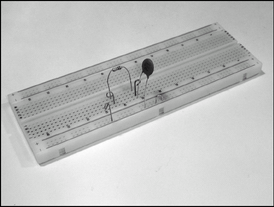
Connect all the resistors in series by using a solderless breadboard (as shown in the figure; see Chapter 3 for more information), soldering them, using clip leads, or just twisting their leads together.
Note
In series: A method of connecting electrical components end-to-end so there is only one current path and the same current flows through all the components being connected together.
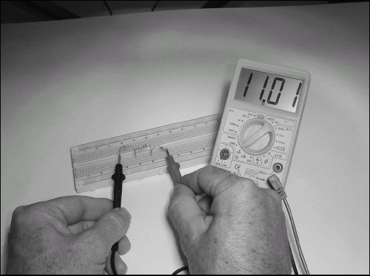
Measure the resistance from one end of the resistor string to the other. You add the values of resistances in series together, so the total resistance should be 100 + 1000 + 10000 Ω= 11100 Ω. It may be a little more or less because the labeled resistance values aren't exact. (See Chapter 1 for more information on component tolerances.)
Now connect all the resistors together in parallel.
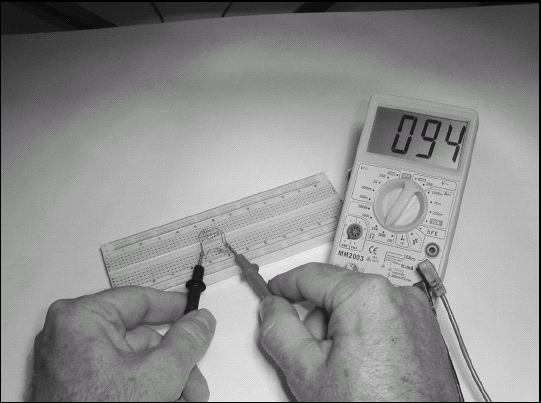
Measure the resistance of the parallel set of resistors. The reciprocal of the sum of the reciprocals (got that?) is how you add resistance values in parallel. Calculate the expected parallel value by taking the reciprocal of each resistor's value, for example, 1/100, 1/1000, and 1/10000. Add these together, for example, .01 + .001 + .0001 = .0111. Now take the reciprocal of that: 1/0.0111 = 90.09Ω. Compare your measured and calculated values.
Note
In parallel: A method of connecting electrical components with one set of leads tied together and the other set of leads tied together so when voltage is applied, the same voltage is applied to all three resistors. In parallel circuits, the current must divide between the different branches of the circuit.
Moving on to Ohm's Law, turn your power supply on and adjust it to 12V output or prepare a battery pack with about the same voltage. Measure the exact value of the 1 kΩ resistor with your multimeter.
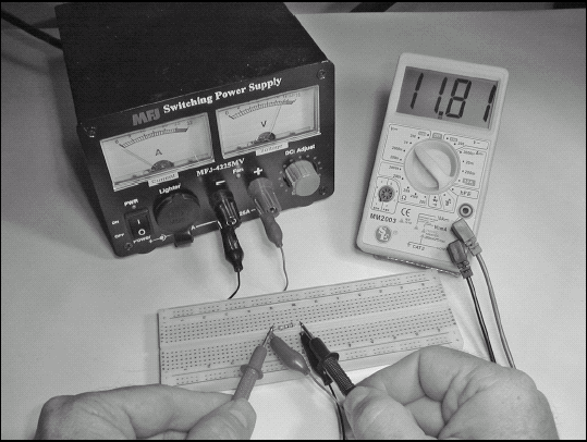
Using clip leads, connect the 1 kΩ resistor between the power supply (or battery pack) + and - terminals, then turn the supply on. Measure the voltage across the resistor. You know voltage (12V) and resistance (the value you measured in Step 7), so use the equation I = E / R to calculate the current flowing through the resistor. If the voltage is exactly 12V and the resistor value was exactly 1 kΩ, the current would be 12 / 1000 = 12 mA.
Connect all three resistors in series again as in Step 3. Apply voltage from the power supply across the ends of the string. Use Ohm's Law as in Step 8 with the total resistance you measured in Step 4 to determine the current flowing in the series string. If your supply voltage is 12V, the current should be close to 12 / 11100 = 1.1 mA.
Now use Ohm's Law to determine what voltage you should measure across each resistor. You know the value of each resistor and the value of the current flowing through the string. Since the same current flows through all the resistors (where else can it go?), the voltage across the resistor is E = I × R. If 1.1 mA is flowing through the 1 kΩ resistor, the voltage across it should be
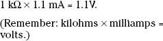
Repeat Step 10 for the 100 Ω and 10 kΩ resistors. What voltage did you calculate for each resistor? (The voltages should be 0.11V and 11.1V, respectively).
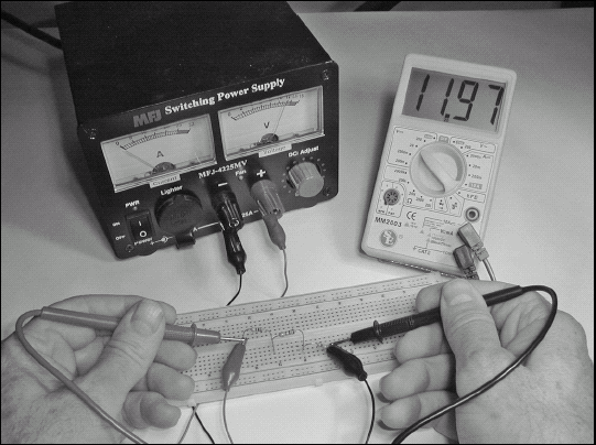
Connect just the 1 kΩ d 10 kΩ sistors in parallel as in Step 5 and measure their resistance as in Step 6. Set up your meter to measure current and connect the meter so current from the power supply's + terminal flows through the meter before flowing through the paralleled resistors.
Calculate the total current you expect to flow through the paralleled resistors from a 12V supply using the value for the resistors in parallel from Step 6. If the voltage is 12V and the parallel resistors measured 909 Ω then I = E / R = 12 / 909 = 13.2 mA.
Apply 12V from the power supply and measure the actual value with your meter. You have now used Ohm's Law in all three ways!
This set of tasks covers the three types of transistors you're most likely to encounter, but there are many, many others. Use the Web resources and your experience to determine how other types may be checked with your multimeter.
Table 12-2 lists test results for the following steps. Tests for meters with the diode-checking function are in the column labeled "DF Result." Tests for analog meters using resistance checks are in the column labeled "RM Result." A red probe is assumed to be connected to the meter's voltage/resistance measurement jack and a black probe to the COMMON jack. Table 12-2 lists each test connection in the red-to-black direction. For example, in the measurement tables, "Anode to Cathode" means to take a measurement with the red probe on the diode's anode leads and the black probe on the diode's cathode lead.
Download the data sheets for each of the diodes and transistors by entering the part number and the words "data sheet" into an Internet search engine. For example, 1N4148 "data sheet." Several sources will be listed for each part.
Tip
Create a Data Sheets folder on your computer. Each time you look up a part's data sheet, download the PDF version and store it in this folder or use PDF printer software to create a PDF version. (If the file is not clearly named, change the name to part number data sheet.) This way you'll build up a library of data sheets you can access any time.
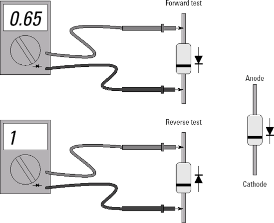
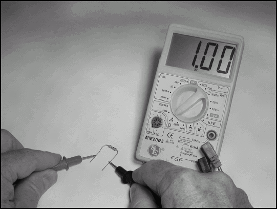
On a 1N4148 diode or 1N4001 rectifier, determine which lead is the cathode by looking for the painted bar at one end. Make the tests as shown in Table 12-2.
Table 12-2. Diode Junction Tests
Test Connection
DF Result
RM Result
Anode to Cathode
0.6 to 0.75V
500 Ω to 2 kΩ
Cathode to Anode
Open
Infinite
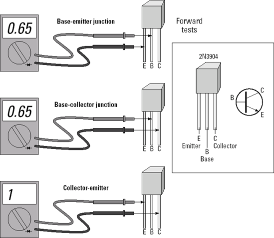
Determine which leads of the 2N3904 transistor are the collector, base, and emitter. The 2N3904 is an NPN device, meaning the collector and emitter are N-type material and the base is P-type material. Therefore, current will only flow from the base to the collector and from the base to the emitter. Make the tests as shown in Table 12-3. (The figure only shows the forward tests.) The most common failure of these small bipolar transistors is from overload, causing low resistance readings (below 500 Ω) across junctions or making junctions act like resistances in both directions.
Table 12-3. NPN Transistor Junction Tests
Test Connection
DF Result
RM Result
Base to collector
0.6 to 0.75V
500 Ω to 2 kΩ
COllector to base
Open
Infinite
Base to emitter
0.6 to 0.75V
500 Ω to 2 kΩ
Emitter to base
Open
Infinite
Collector to emitter
Open
Infinite
Emitter to collector
Open
Infinite

Determine which leads of the 2N3906 transistor are the collector, base, and emitter. The 2N3906 is a PNP device, meaning the collector and emitter are P-type material and the base is N-type material. Therefore, current will only flow from the collector to the base and from the emitter to the base. Make the tests as shown in Table 12-4. The most common failure of these small bipolar transistors is from overload, causing low resistance readings (below 500 Ω) across junctions or making junctions act like resistances in both directions.
Table 12-4. PNP Transistor Junction Tests
Test Connection
DF Result
RM Result
Base to collector
Open
Infinite
Collector to base
0.6 to 0.75V
500 Ω to 2 kΩ
Base to emitter
Open
Infinite
Emitter to base
0.6 to 0.75V
500 Ω to 2 kΩ
Collector to emitter
Open
Infinite
Emitter to collector
Open
Infinite

The 2N7000 is the most common type of MOSFET as described in the sidebar; an N-channel enhancement MOSFET. As Table 12-5 shows, MOSFETs are tested differently than bipolar transistors because the gate is completely insulated from the drain and source so no current flows in the gate terminal. Due to their construction, MOSFETs have a built-in source-to-drain body diode that tests like a regular silicon diode. There are two common failures of small MOSFETs. Gate punchthrough breaks down the gate insulation resulting in low resistances (less than 10 kΩ) between the gate and drain or source. Overload can cause the drain-to-source resistance to be low (less than 500 Ω in an enhancement mode transistor).
For this task, you won't be able to use a multimeter (unless it's one of the more capable digital meters with a frequency counter built-in). As a result, this task uses an oscilloscope. If you don't have an oscilloscope of your own, ask around and see if someone you know has one or knows someone that does or has access to a scope. Many hobbyists have one!
Before beginning this task, familiarize yourself with oscilloscopes in general by reading through the tutorials listed in Chapter 11. Your scope may not have exactly the same control arrangement or labeling, but all of them have the same basic features that you'll use in this task.
Inspect your scope and find the calibration output. It should be on the front panel and may be labeled "CAL." On most scopes it's a small, exposed terminal or jack. The CAL signal is usually a 1 kHz square wave with an amplitude of 1VPK-PK or less. You use the CAL signal to check the scope display and adjust the test probes as described in the scope manual. (If your scope doesn't have a CAL signal output, use your function generator to produce a 1 kHz, 1VPK-PK square wave.)
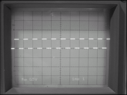
Set up the scope for a vertical gain of 0.5 V/div (use Channel 1 or A if it's a multiple-channel scope), and a sweep speed of 1 ms/div. Set the trigger mode to AUTO. You should see a bright line or trace on the display. Adjust the Vertical Position control so the trace is on the graticle at the center line. Adjust the Horizontal Position control so the trace is approximately centered left-to-right. (If you can't see the trace, most scope manuals include a procedure for setting all controls so a trace should be visible. There are a lot of settings on a scope and some of them can move the electron beam off-screen or prevent it from sweeping across the display.) Adjust the Focus control for the sharpest, narrowest trace. Adjust the Brightness or Intensity control so the trace is easy to see on the display, but doesn't blur.
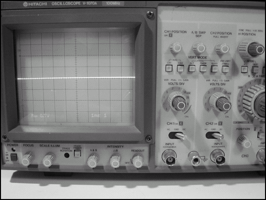
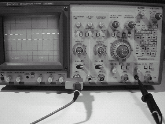
Connect a test probe to Channel 1 and attach the end of the probe to the CAL terminal or jack. You should now see a square wave on the display instead of the straight line trace. If the trace disappears, you may have the vertical gain improperly set. Reduce vertical gain (set the control to higher values of voltage per division) to see if the waveform appears.
Determine the amplitude of your scope's CAL signal by counting the vertical divisions between the square wave's maximum and minimum voltages. You can make a more accurate count by using the scope's Horizontal Position control. Move the waveform's upper and lower portions so they are next to or cross the more finely graduated center vertical axis. Multiply by the vertical gain in volts per division. This gives you the peak-to-peak voltage of the waveform.
Repeat your amplitude measurement at higher and lower vertical gain settings, making the waveform smaller and larger. When the waveform is small, the width of the trace itself can introduce error into the measurement: It's hard to tell if you measure at the top, bottom or center of the trace. Amplitude measurements are best made with the waveform as large as it can be and still be completely within the graticle. This minimizes the effect of the trace width on the measurement.
Tip
If you want, repeat each amplitude measurement that follows with your multimeter to get a feel for how multi-meter and scope voltage measurements compare.
Determine the frequency of your scope's CAL signal by counting the horizontal divisions between the square wave's low-to-high edges or transitions. Use the Horizontal Position control to move the left-hand edge to a vertical line on the graticle. The center horizontal axis is your measuring scale. Multiply the number of divisions by the horizontal sweep speed in time per division to get the period of one cycle of the waveform. Its frequency is the reciprocal of period (1/period). (If you have a frequency counter, connect it to the CAL output and compare its reading with yours.)
Repeat your frequency measurement at faster and slower sweep speed settings, stretching and compressing the waveform horizontally. As with amplitude, the most accurate measurements of period are made with the waveform as large as it can be and still have one complete cycle completely within the graticle.
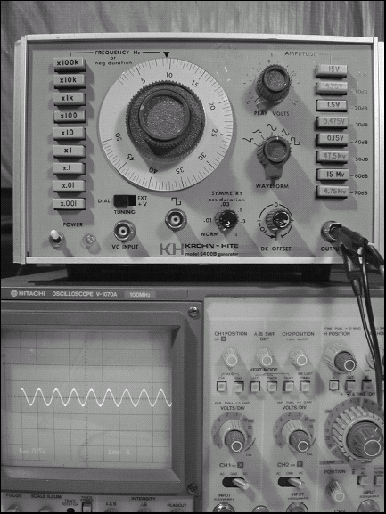
Reconnect the test probe to the output of your function generator. Replicate the CAL signal with the generator. For example, a square wave with the same amplitude and frequency. Confirm that you have the same type of waveform and displayed trace.
Switch the generator to output a sine wave without changing the amplitude or frequency. How can you measure frequency and amplitude now? Measure amplitude by using the Horizontal Position to move the waveform maximum and minimum points exactly on the center vertical axis to count divisions. Since sine waves don't have sharp vertical edges, use the points at which the waveform crosses the center horizontal axis as your measurement points.
Try other waveforms that your generator can produce to practice making amplitude and frequency measurements on those shapes. You'll find that each shape requires a slightly different technique to count vertical and horizontal divisions accurately. The key to making good measurements with a scope is being able to view a stable trace and positioning it correctly on the graticle. By practicing, you'll become skilled in applying this powerful "electronic eye" to your circuitbuilding activities.
In this task, I'll show you the formulas for calculating decibels and you'll get some practice in converting voltage measurements to decibels.
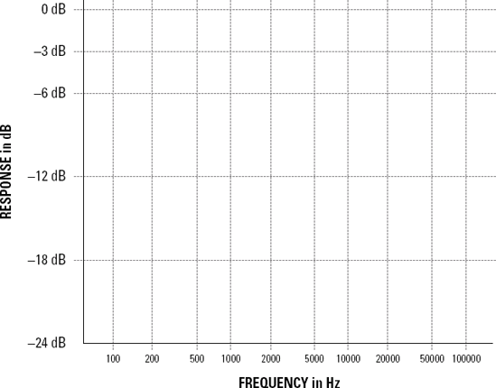
This graph shows decibels (dB) on the vertical axis and frequency on the horizontal axis. By plotting a circuit's output-to-input ratio in dB at different frequencies, the graph shows frequency response. Frequency is shown logarithmically to show equal ratios of frequencies as equal space along the axis. This gives a better picture of how the circuit responds than if frequency was shown linearly.
Inspect your meter and set it to measure AC voltage.
Set the function generator to output a 1 kHz sine wave of 2VRMS amplitude.
Connect the three resistors in series (see the task "Measuring Resistance with Ohm's Law" earlier in this chapter). Use clip leads to connect the string of resistors to the output of the function generator.
Measure the voltage across the 10 kΩ resistor. It will be about 90% of the total voltage from the generator. Using the generator output of 2VRMSas Voltage 2, calculate the attenuation of the voltage across the 10 kΩ resistor using the equation dB = 20 log (measured voltage / 2VRMS). The result should be about −0.83 dB.
Measure the voltage across the 1 kΩ resistor and perform the same calculation. The result should be about −20.9 dB.
Measure the voltage across the 100 Ω resistor and perform the same calculation. The result should be about −40.9 dB.
What is 2VRMSin dBV? Use 1VRMSas Voltage 2 in the equation.
Convert each of the voltages you measured across the resistors to dBV using the equation dB = 20 log (measured voltage / 1 VRMS). The answers are 5.2 dBV, −14.8 dBV, and −34.9 dBV.
One of the most closely read specifications (or "specs") of home audio equipment is its frequency response. For example, an amplifier may be rated at full output from 20 Hz to 18 kHz. What does that really mean? When discussing an amplifier, it means that below 20 Hz and above 18 kHz, the amplifier's output power will be less than half of the output between 20 Hz and 18 kHz.
Frequency response is relative; that is, it's related to some reference measurement or level of performance. Because frequency response is relative, it's measured in dB. In the amplifier example, frequency response shouldn't depend on how loud the output is or isn't. By using dB, the measurement is made to be independent of output volume.
Frequency response is just one of many types of measurements that use dB to give relative results. In this task, you'll make a set of measurements on a simple circuit that show you how to combine frequency measurement, voltage measurement, calculate dB, then graph the result in the standard way that other circuitbuilders will understand.
Inspect your meter and set it up to measure AC voltage. Set your function generator to output a sine wave, at 100 Hz, of about 2VRMS. (The exact voltage isn't critical, as long as it isn't changed during the task.)
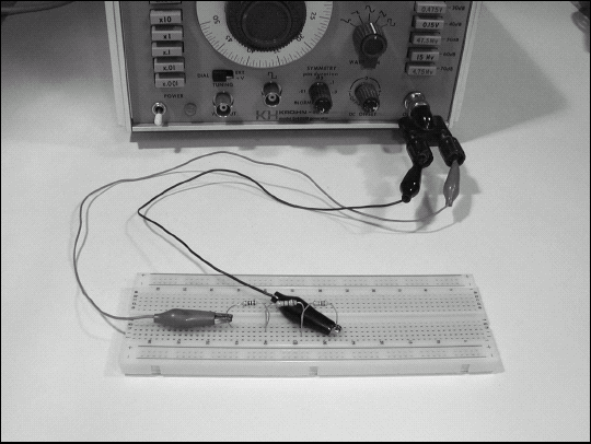
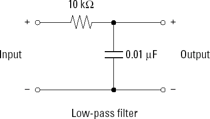
Build the circuit shown in the figure. You can use clip leads and twist component leads together if you want. A solderless breadboard is a little easier to use. Use the function generator's output connector shell as the circuit ground.
Note
This circuit is a low-pass filter — its output gets smaller and smaller as frequency increases because at higher frequencies the capacitor becomes closer and closer to a short circuit. Filters made from resistors and capacitors are called RC filters.
Turn on the function generator and measure its output voltage directly at the output connector. Record this voltage — it's the reference voltage for all dB calculations.
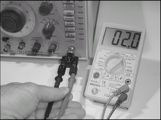
Reconnect the multimeter to the capacitor, one probe on each lead. You should read approximately the same voltage on the multimeter.
Set the function generator's frequency to all the frequencies in Table 12-6, taking a voltage measurement at each one.
Table 12-6. Frequency Response Measurement Table
Frequency in Hz
Voltage in VRMS
Response in dB
100
X
0.0
200
X
X
500
X
X
f0
X
−3.0
1000
X
X
2000
X
X
5000
X
X
10000
X
X
20000
X
X
50000
X
X
100000
X
X
Readjust the frequency until the multimeter reads 0.707 times the reference voltage you measured in Step 3. This should be around 1600 Hz for the values of resistance and capacitance in the circuit. (Any frequency between 1200 and 2000 Hz is reasonable.) This frequency is called the filter's cutoff frequency or corner frequency because this is the point at which the filter's output power is half that of the input power from the signal generator.
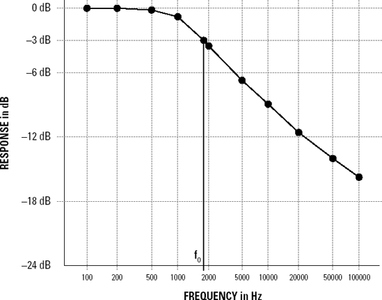
Calculate the dB response for each frequency and plot all the points on the graph paper. Use a ruler to draw a line from the lowest-frequency point to the next lowest. From that point to the third-lowest, and so forth, eventually creating a curve that describes the filter's frequency response. Draw a vertical line from the point located at the cutoff frequency to the frequency axis. Label that point "f0". You've just drawn a frequency response curve!
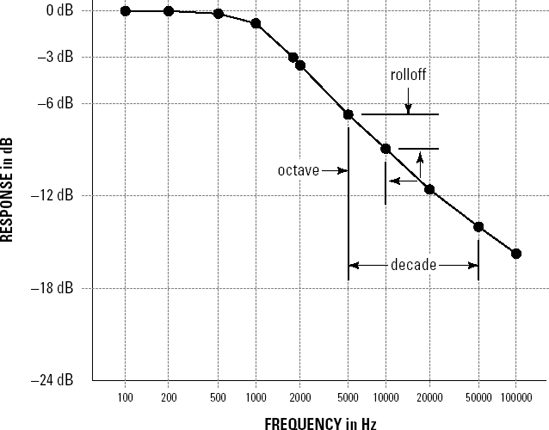
Above f0, the response curve quickly becomes a straight line sloping down as frequency increases. Subtract the dB response at 10 kHz from the dB response at 5 kHz. This is one octave of difference in frequency. The difference in dB over a change of one octave is the filter's rolloff in dB/octave. Subtract the dB response at 50 kHz from the dB response at 5 kHz. This is one decade of frequency difference and the rolloff is in dB/decade. Both figures are often used to describe a filter's frequency response.
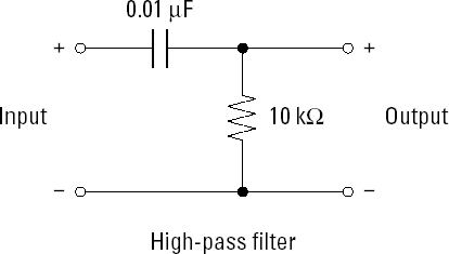
While you have the equipment all set up, change the filter to a high-pass filter by exchanging the positions of the resistor and capacitor. For example, the capacitor is connected to the function generator's output, then to the resistor, which is then connected back to the output connector's shell. Repeat the measurements and graph the results.