With electronic equipment seemingly everywhere and much of it wireless, is it any wonder that sometimes they interact in ways we don't expect? The result can be an occasional glitch, a bit of noise, or even complete disruption. This chapter will show you — a circuitbuilder and electronic-er — how to take the initiative and keep your equipment operating properly.
Interference, either to or from your electronics, refers to unwanted signals or the effects caused by other signals. There are two types of interference: the kind you experience from external sources and the kind caused by your devices. We'll start with interference that your stuff receives externally — starting with radios and other RF receivers (some of them inadvertent) that you might have. Figure 17-1 shows several examples of interference-fighting devices and components as follows:
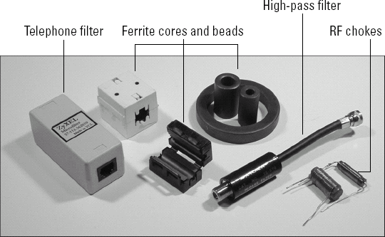
Figure 17-1. All these devices and components can be used to reduce or eliminate radio-frequency interference.
The first thing to do when you are receiving interference from radio signals is to make sure your own radio or receiver isn't causing the problem. Modern radios have very sensitive receivers, but that makes them susceptible to interference or even causes them to generate false or spurious signals that seem like interference from another signal.
Overload is a common problem in urban and suburban areas. Sensitive receivers can only withstand so much received signal strength before their input circuits are overpowered by an unwanted signal. If you live near a strong broadcast or paging transmitter, you may experience overload. A strong signal from a nearby amateur radio station — operating completely legitimately — may overload nearby receivers. The interfering signal doesn't even need to be in the same frequency range that the receiver is tuned to. This is a common problem for stereos and televisions. When overload occurs, the receiver's output becomes distorted and erratic.
The resulting interference is not the fault of the transmitting station at all. The best solution is to reduce the strength of the interfering signal at the receiver with a filter. There are too many different circumstances to give specific solutions, but Table 17-1 provides some guidance and the task of installing a filter at a television receiver's input is presented as an example later in this chapter.
Table 17-1. Interference-Reducing Filters
Electronic equipment not designed to receive radio signals can act like a radio receiver, too. You may not think you have antennas connected to your electronics, but look again — every cable and cord you have plugged in acts like an antenna for any radio wave that goes by! The diodes, transistors, and ICs in the circuits connected to the cable all act as crystal radio sets, converting the radio wave to an interfering signal inside your equipment! This is called direct detection. A good example might be garbled audio from public-address system picking up a two-way radio transmission, even though it doesn't have a single radio circuit inside.
The solution in direct detection is to install radio wave absorbing chokes on the cables to prevent the signals from getting inside your equipment in the first place. The cables can be wound onto a core as shown in the "Installing a Split-Core Ferrite Choke" task later in this chapter. Ferrite cores can also be installed on cables that are too big to conveniently wind onto a core.
By winding a cable onto a ferrite core, the effect of the ferrite is multiplied with each additional turn through the center of the core. In the task later in this chapter, you'll see how a power cord is wound onto a split core that's available at most electronic component stores.
Even non-radio equipment can cause interference! This is more accurately referred to as EMI (electromagnetic-frequency interference) or RFI (radio-frequency interference). Signals can leak out of your equipment from an oscillator or clock signal — this is often a problem with digital circuits that operate with high-speed pulses. In this case, you apply the same filtering techniques — but from the inside!
Instead of large ferrite chokes on the cables outside the equipment or low-pass filters in the cables themselves, filtering is performed on the signals before the interfering energy can leave the equipment.
Tip
The filtering techniques in this section work in both directions! By adding filtering to your device's external connections, you reduce the signals generated by your circuit and also reduce its susceptibility to interference from outside. Adding filtering is just about always a good practice.
Note
If your electronics are radiating signals of any sort, your device is an unintentional radiator under the FCC's "Part 15" rules that govern unlicensed devices. Part 15 devices are required to accept any interference they experience or to stop operating if they cause interference to an FCC-licensed station. Commercial Part 15 devices, such as cordless phones and wireless network gadgetry, have this spelled out in their operating manuals or on a sticker right on the equipment. These rules allow useful unlicensed devices to coexist with the more capable licensed radio services.
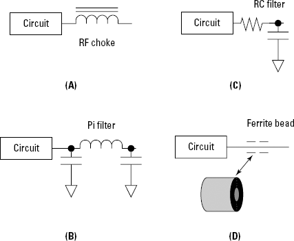
Figure 17-2 shows four ways to add filtering to the input and output connections of your circuits so you can prevent interfering signals from entering or leaving.
At 17-2(A), two RF chokes are shown. These are intended for use in power-supply connections. They're wound with heavy wire and can handle several amps of current. These chokes are very effective at suppressing RF signals up to 10 MHz or so.
At 17-2(B), a Pi filter is shown. The name "Pi" comes from the arrangement of the two capacitors and an inductor on the schematic — it looks like the Greek letter π. Depending on the frequency range of interest, the capacitors are from 100 to 1000 pF and the inductor from 0.1 to 10 μH. Some manufacturers also sell EMI filters of this type as small components that resemble capacitors.
The circuit at 17-2(C) is called an RC filter because it's made of a resistor and a capacitor. The capacitor is typically on the output side and is 100 to 1000 pF. The resistor is chosen so the cutoff frequency of the filter is high enough so the desired signals are not affected, but low enough to insure that RF signals are attenuated. The cutoff frequency of the filter is fC = 0.159/RC. (L measured in henries and C in farads)
17-2(D) shows the symbol for a ferrite bead. Ferrite beads can be slipped onto individual wires if a large core is too cumbersome. The beads are typically ¼" in diameter or smaller and several may be used on one wire. Beads of this size work best for signals above a few MHz and on wires carrying minimal current.
If your television is receiving interference on many channels from a single strong nearby signal, it's likely that the television receiver is over-loading. Luckily, there is a simple fix if the interfering signal is of a frequency below that of television signals. The lowest-frequency TV signal is found at channel 2, between 54 and 60 MHz. A high-pass filter reduces (attenuates) lower-frequency signals. A typical TV-type high-pass filter is shown in Figure 17-1. (The MFJ Enterprises MFJ-711B is a good choice, www.mfjenterprises.com/products.php?prodid=MFJ-711B).
These are easy to install as shown in this task.
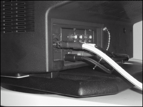
Locate the input cable to your TV, DVD player, or VHS recorder as shown in the photo. It will be a Type F connection (see Chapter 8).
Warning
Check with your cable TV or satellite receiver provider before installing any filters in the input cable to the receiving equipment. These systems use different ranges of frequencies than over-the-air TV receivers. Luckily, these systems rarely experience overload. The cables to satellite antennas also carries DC voltages to power the receivers and switches. Installing a filter in the feedline may block or short out the DC power, preventing the system from working.
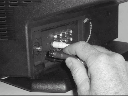
Disconnect the cable by unscrewing the connector.
Connect the cable to the threaded end of the filter. Seat the connector firmly with the pliers. Do not overtighten — you just want a secure connection.
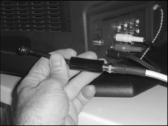
Confirm that the center conductor in the center of the Type F connector at the other end of the filter is not bent or pushed back into the connector. It should extend slightly beyond (or be flush with) the end of the connector's screw-on shell.
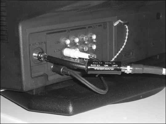
Screw the shell of the filter's connector onto the threaded connector on the equipment. Tighten with the pliers.
Turn on the equipment to make sure that you're still receiving signals and that their quality is good.
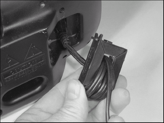
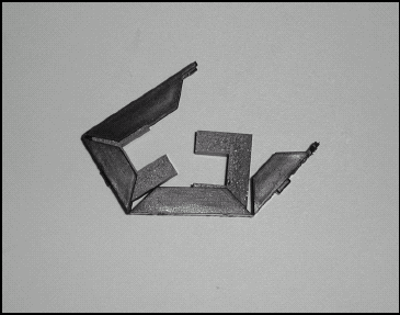
It's quite common for RF signals to cause interference in consumer electronics, entering the equipment via the power cord. Plug-in RF filters are available, but can be expensive. A more cost-effective first step is to use a split-core ferrite choke, winding the power cord through it several times.
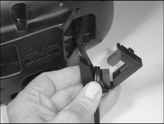
Open the split core by releasing the locking catch at one corner of the plastic housing.
Starting as close to the equipment as you can, wrap the cord through the center of the core until the center of the core is filled. All turns must be wound in the same direction to avoid canceling the effects of the core.
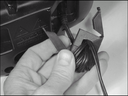
When the core is full, slide the other half of the core onto the cable so the halves meet securely.
Keep the halves together by securing the locking catch.