All the tasks in this chapter involve putting connectors on a piece of coaxial cable to be used with some kind of radiofrequency (RF) signal — TV, citizens band (CB), or amateur (ham) radio, or a scanning receiver. These connectors and the cable are a bit special because they have to carry signals that are far higher in frequency than audio and power. Radio receivers have to work with signals that are incredibly weak — a billionth-of-a-watt signal is considered very strong! CB and amateur transmitters depend on the connector being just right so they can deliver all that precious radio power to the antenna. A short bit of background on coaxial cable will help you understand why special care is needed for radio frequency connectors.
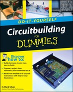
Coaxial cable (or just "coax" for short) has two conductors that share a common central axis; they are co-axial. You can see this for yourself by looking at the end of a piece of coaxial cable. (Go ahead, I'll wait!) See? Figure 8-1 shows the parts of the cable a little more clearly. The signal carried by coaxial cable flows on the center conductor and on the inside of the outer shield. None of the internal signal is intended to flow on the outside of the shield; here the flow is similar to water in a hose. Coax is used for routing RF signals around your house or in the car because it protects the RF signals from interference and noise. No matter what contacts the outside of the shield, the signals inside are unperturbed.
Note
Conductor: In a cable, a conductor is any metal wire, foil, or woven braid that carries a signal. In a cable with multiple conductors (known as multi-conductor), each conductor is electrically insulated from all the other conductors. Coaxial cable has two conductors (the center conductor and the shield) that share a common central axis.
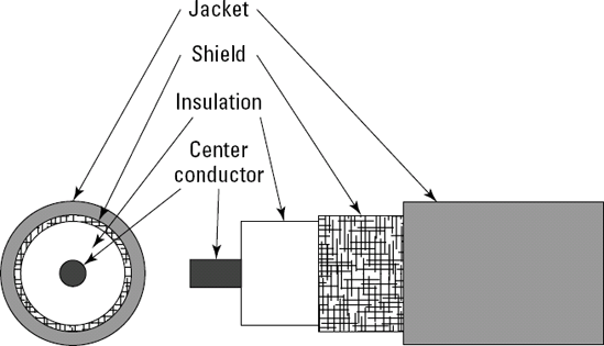
Figure 8-1. In coaxial cable, two conductors — the center conductor and the shield — share a common central axis.
Note
Frequency: In alternating current, electrons move backward and forward in a regular pattern known as a cycle. Each cycle comprises one back-and-forth movement. Frequency is a measure of how cycles occur every second. Frequency is measured in Hertz (Hz), which is the same as a cycle per second. Different units of frequency are abbreviated kHz (kilohertz), MHz (megahertz), and GHz (gigahertz).
Note
Radio frequency (RF): RF signals have frequencies higher than 30,000 Hz. AM radio signals have frequencies of 550 to 1700 kHz (kilohertz). FM signals range from 88 to 108 MHz (megahertz).
Tip
All coaxial cable are not the same, even though they all have the same arrangement of center conductor, insulation, and shield. Each type of coax has a characteristic impedance, usually 50 or 75 ohms. This value relates to how the RF signals flow in the cable; it's not the resistance you might measure with your multimeter from end to end. TV and video systems have standardized 75-ohm cable such as RG-6, RG-11, and RG-59. Radio systems usually use 50-ohm cables such as RG-8, RG-58, and RG-213. Using the right cable is important in getting the best system performance.
As you might have guessed, protecting the integrity of that outer shield is really, really important. Any loss of integrity in a connector for RF signals generally means poor or no reception, lots of noise and interference, and unhappy transmitters. That's why it's also really, really important to install coax connectors properly. The crimp-on connectors and crimping tool make that process fairly easy, as long as you follow instructions and don't cut corners.
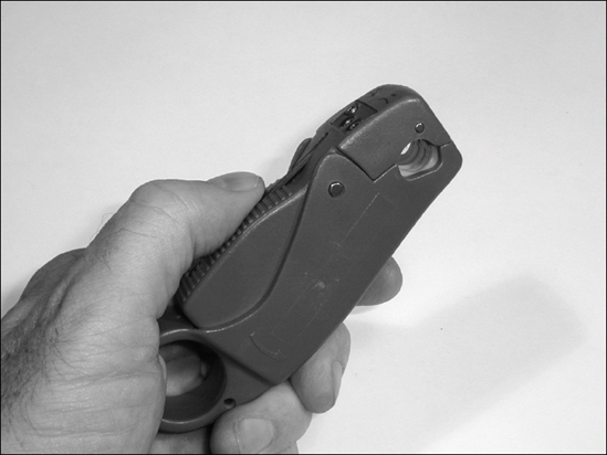
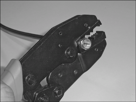
The coaxial connector crimping tool (which we'll call a coax crimper to save our breath) in Figure 8-2 is heavier and stronger than the plastic crimpers used for telephone cable. It has to be to crimp metal rings and tubes!
This type of coax crimping tool uses a compound ratchet action to multiply your hand's squeezing force. Between the blue handles you can see the teeth of the ratchet. Using a ratcheting action ensures a consistent crimp, even if it takes a couple of squeezes to get the job done. If you get part of the way through a crimp and decide that you need to stop crimping and release the connector, look for the ratchet-release lever just behind the ratchet cam. Push this lever forward to release the ratchet and open the crimper's jaws. When you have squeezed the crimper completely shut, the tool automatically releases the ratchet and opens its jaws. Give this a try with your own coax crimper. You'll hear the clickety-click as the jaws come together, then a pause, followed by one or two more clicks as the automatic release occurs.
The business end of the crimper is its jaws. The jaws hold a pair of complementary dies that have hexagonal holes for the connector pieces. The crimper's instructions will show you which hole to use for which connector and cable type. The large holes are used to crimp a metal crimping ring over the cable's shield. The small holes crimp the connector's center pin (if there is one). When you purchase a coax crimper, be sure to get a model that comes with the proper dies for connectors and the type of cable you'll be working with.
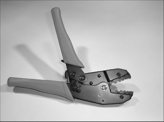
Because radio signals come in so many forms, frequencies, and strengths, one or two types of connector just can't do all the jobs properly. The different types of connectors that have been created to do those jobs are grouped into families. Within each family, there are plugs, receptacles (also called jacks or sockets), and adapters — connectors that mate plug to plug, receptacle to receptacle, and even allow connections between connector families. In most electronic work, you only encounter the three connector families described in this chapter: Type F, UHF, and BNC. Examples of connectors and adapters from these families are shown in Figure 8-3. Table 8-1 lists the common names or designators for the most common connectors in each family.
Table 8-1. Coax Connector and Adapter Designators
Type F | UHF | BNC | |
|---|---|---|---|
Plug (Male, RG-6/RG-8X/RG-59 cable) | Plug (listed by cable type) | PL-259 plus UG-176 reducing adaptor | UG-260B/U |
Plug (Male, RG-58 cable) | Plug (listed by cable type) | PL-259 plus UG-175 reducing adaptor | UG-88B/U |
Plug (Male, RG-8/RG-213 cable) | Plug (listed by cable type) | PL-259, no reducing adaptor | UG-959/U |
Receptaple (Female) | Panel | SO-239 | UG-1094/A |
Double female or barrel | Barrel or double female | PL-258 | UG-914S |
Double male | Male-to-male | PL-269 | UG-491A |
Bulkhead (routes connections through panels or walls) | Bulkhead or double female | PL-224, PL-363 | UG-492A |
Type F connectors are very inexpensive and easy to install. You have seen them on the ends of the cable that connects your TV to a cable TV wall outlet. They are designed for coaxial cables that have a solid center conductor. To make installation really easy, these connectors don't even have a center pin — they use the cable's center conductor instead! The body of the plug has a threaded ring called a shell that screws on to receptacles and female adapters.
Like Type F connectors, the UHF connector family is threaded, meaning they attach to each other using threaded shells. (In this case, the name UHF is not related to the Ultra High-Frequency band of TV signals.) The shells of UHF connectors are separate from the connector body. UHF connectors are widely used for CB and amateur radio, shortwave broadcast receivers, marine radios used on boats, and commercial radios.
The stock version of the PL-259 plug is made to be fitted to RG-8 coaxial cable or one of the same diameter, such as RG-213. To be used with the smaller coax that's more common with CBs and mobile radios (RG-8X or RG-58) a reducing adapter must be screwed into the back of the plug.
The BNC connector family of connectors is found on scanners and other receivers and is also common on electronic test equipment. It is a bayonet-style locking connector. (The UHF and Type F connectors are threaded.) To connect a BNC plug to a BNC receptacle, align the bayonet pins of the receptacle with the slots of the plug, slide the connectors together and twist clockwise until the pins slide into the locking position, called a detent. To unplug, press the connectors together, freeing the pins, and twist counterclockwise.
BNC connectors are used primarily with smaller coaxial cables; RG-6, RG-58, and RG-59. Remember to purchase the BNC connector designed to fit your cable. Your coax crimper must also fit the cable. As with UHF connectors, a traditional style of connector is available that uses solder to attach the center pin and a screw-in compression clamp to connect the braid. These work well, but they take a lot of practice to install correctly. Compression-style connectors similar to Type F compression connectors are available, as well. As a beginner, stay with the crimp or compression type connector.
Adapters are available for almost any combination of plugs and receptacles imaginable. In addition, you can combine or reroute cables with tee adapters that join three cables (all-male, all-female, 2-male, 2-female), or right-angle adapters that make connections in tight spaces.
If you expect to be installing a lot of RF connectors, you should spend a few bucks and get a coax stripping tool or coax stripper of the type shown in Figure 8-4. This convenient little wonder makes short work of trimming the cable jacket and making a nice clean cut into the center insulation without nicking the center conductor. What takes a minute or more using a knife or razor blade takes less than ten seconds with this tool. You can buy a coax stripper wherever you buy your coaxial cable and coax crimper.
Coaxial cables carrying TV signals, whether from an antenna or a cable TV system, connect to a TV set or DVD player using a Type F connector. There are two types of crimp-on Type F connectors; the original crimp connectors with a separate crimp ring and the direct crimp connectors with the inner and outer crimp surfaces an integral part of the connector. This task shows the direct crimp style, but the same instructions can be used for both types as long as you remember to slide the first type of connector's crimp ring onto the cable first!
It is important to get the type of connector that matches your coaxial cable. When in doubt, ask a salesperson. The variations between connector types are small and hard to judge by eye. The packaging or description of the connector will state what cable types the connector will fit — RG-59, RG-6, RG-6A, RG-6 tri-shield, RG-6 quad-shield, or RG-11. Don't try to use the wrong type of connector! Even if you can get the connector on the cable, the connection will soon degrade, work loose, and fail.
Start by cutting the end of the cable square and clean. If your connector has a separate metal ring, slide it on to the cable now.
Read the assembly instructions on the connector packaging (or the manufacturer's Web site) to determine how much of the jacket, shield, and center insulation to remove. Different manufacturers and styles of connectors require different amounts of shield (just braid or braid-and-foil) to be exposed. All Type F connectors require a quarter inch of the cable's center conductor to be exposed.
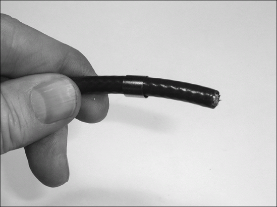
Strip the cable according to the instructions, using a coax stripper or very sharp knife. Be sure you don't nick the cable's center conductor. If nicked, the wire will break after flexing once or twice; if you nick the wire, it's best to start over. The end of the cable should look like the figure. (Note: if you are installing connectors on quad-shield cable that has double layers of braid and foil, the stripping process should only remove the outer set of braid and foil.)
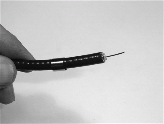
If required by the instructions, fold the braid back and over the cable jacket. Make sure none of the tiny strands of braid cable are making a short circuit to the center conductor wire. Otherwise, trim the braid and foil flush with the end of the jacket as shown.
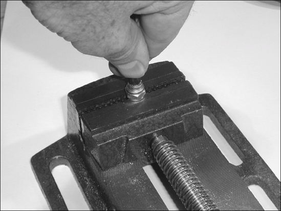
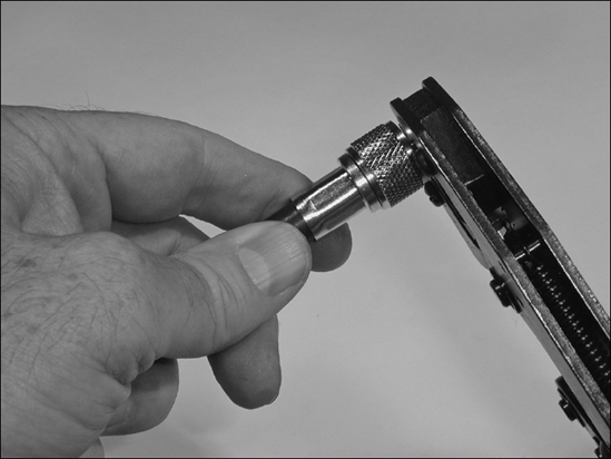
Push the body of the connector onto the cable without turning it from side to side. The inside sleeve of the connector should go under the braid and jacket. Press against a vise as shown in the figure. Keep pushing until the end of the center insulation is at the base of the connector's front section and the center conductor sticks out through the center hole, not touching it at all and slightly beyond the end of the connector. If your connector has a separate metal ring, slide it back over the braid or jacket, keeping the braid folded back over the cable jacket. The ring should be as close to the connector body as possible.
Note
If the connector can be easily pulled off with your fingers, it wasn't installed properly. The most likely reasons are not stripping the cable to the right dimensions or letting the connector slip off the end of the cable as you inserted it into the coax crimper. You can't reuse or recrimp the connectors, so cut it off and start again.
Place the entire connector assembly in the appropriate hole of the coax crimper's jaws so the crimp ring is centered within the hole. Don't let the cable slide back out of the connector — keep it seated firmly in the connector!
Squeeze the handles of the coax crimper, evenly and firmly, until the ratchet is released. Give the connector a close visual inspection to be sure the center conductor isn't contacting any part of the connector body and is approximately flush with the front surface of the connector. Repeat Steps 1 through 6 if you're making a jumper with connectors on each end.
Just like TV signals, citizens band (CB) radios depend on high-quality connector installation for maximum range on both transmit and receive. CB radios use frequencies near 27 MHz — definitely radio frequencies! This task demonstrates how to install the most common type of connector used on CB radios — the PL-259. The connector attaches to the cable in much the same way as the Type F connectors in the previous task. Make sure you have the right connector for the size of cable being used; RG-8 (or RG-213), RG-8X, RG-59, or RG-58.
The coax crimper used for PL-259 connectors operates exactly the same as the Type F coax crimper used previously. In fact, many coax crimpers can do both Type F and PL-259 crimps — or can be made to by changing the dies in the crimper jaws.
There's a lot more information about how to install and operate amateur and CB radios and antennas in the author's books, Ham Radio For Dummies and Two-Way Radios and Scanners For Dummies (both published by Wiley Publishing, Inc.).
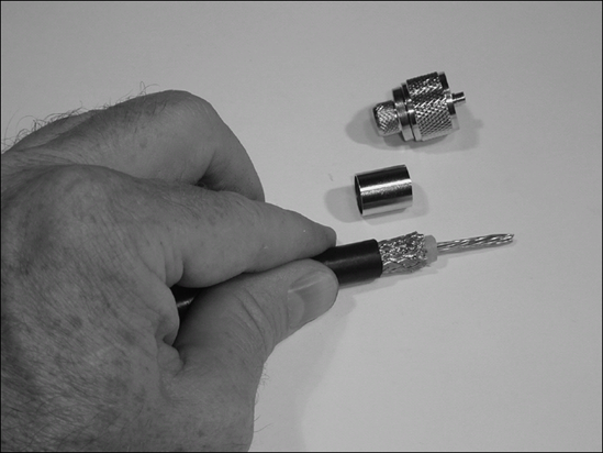
Start by cutting the end of the cable square and clean. Then take a minute to read the manufacturer's instructions for assembling the connector. You can find the instructions on the connector package or on the manufacturer's Web site.
If you are using a coax stripping tool, use it to remove the jacket, braid, and center insulator in a single operation; then proceed to Step 5. Otherwise, as seen in the figure, use a sharp knife or razor blade to score and remove the cable jacket so the shield braid is exposed according to the assembly instructions. If you don't have assembly instructions, remove enough jacket so that the braid extends about ⅛" past the end of the connector's hollow tip; make sure the jacket is even with the base of the connector. Be careful to avoid nicking the braid where the jacket is removed.
Trim the braid according to the instructions or so the remaining length is equal to the length of the crimping ring.
Score and remove the center insulator from the end of the braid, exposing the center conductor according to the instructions. If the center conductor is stranded wire, be sure all the strands stay together and do not fray or bend. Be careful to avoid nicking the center conductor.
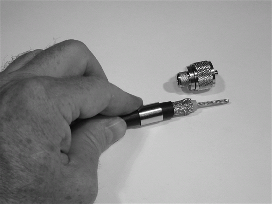
If required by the instructions, fold the braid back over the jacket and slide the separate metal crimping ring onto the cable. Otherwise, slide the metal ring over the jacket.
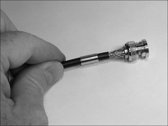
Push the body of the connector on the cable so the center conductor goes through the hollow center pin and the inner crimp surface slides under the braid. Keep pushing until the connector body is seated against the braid and jacket. Use a multimeter to check the resistance between the center pin and the shell — it should show an open circuit. If it doesn't, one of the center conductor strands may not have gone into the hollow center pin — pull the cable out, check it, and then reassemble.
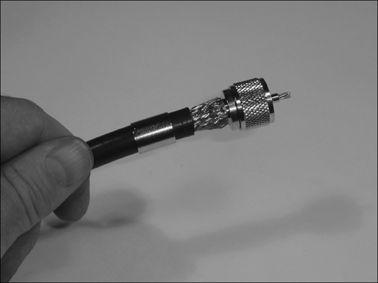
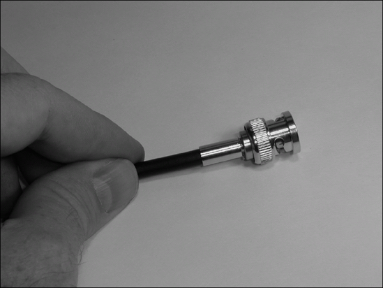
Slide the crimping ring over the braid folded back against the jacket until it is touching the connector body.
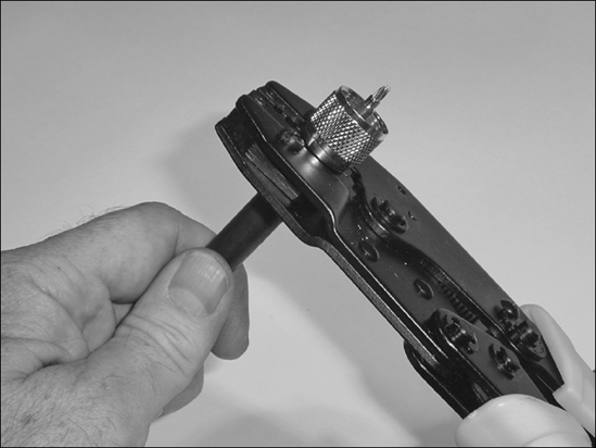
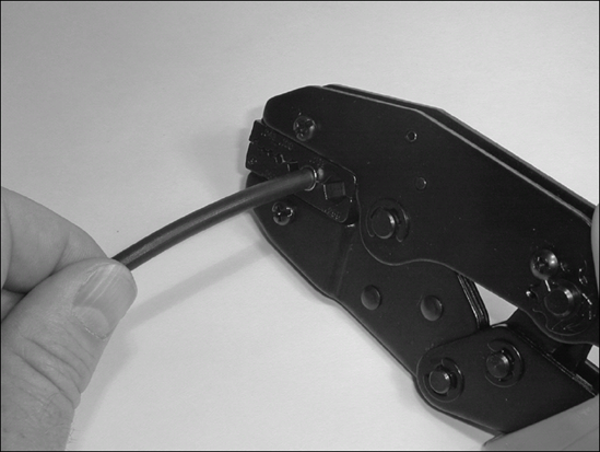
Place the entire connector assembly in the appropriate hole of the coax crimper's jaws so that the crimp ring is centered within the hole. Don't let the cable slide back out of the connector — keep it seated firmly in the connector!
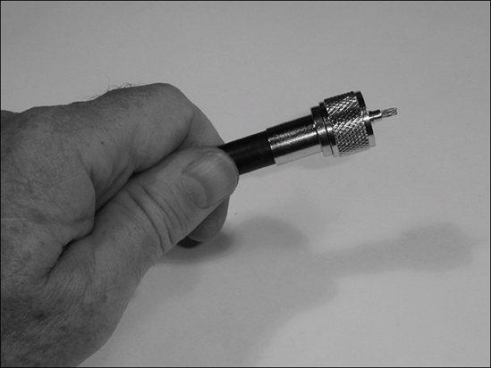
Squeeze the handles of the coax crimper evenly and firmly until the ratchet is released.
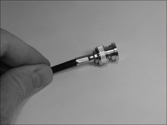
Now crimp the center pin of the connector in the same way. (Many people solder the center conductor for good measure after it's been crimped.) Trim any exposed center conductor or braid. Use a multimeter to check the resistance between the center pin and the shell — it should show an open circuit. If it doesn't, you'll have to cut off the connector and try again!
Scanners have become quite popular for everything from keeping up with the local police department to listening in to crews and drivers at the race track. The range of portable and handheld scanners can be greatly improved with an antenna mounted outside and clear of obstructions and metal objects, connected to the scanner with coaxial cable that has a coax connector at each end. This task shows you how to install a BNC plug that can connect to most scanners.
If the length of coax between your scanner and the antenna is significantly more than 50 feet, you may want to consider using larger, lowerloss coax such as RG-8. But the larger cable can be too stiff for convenient attachment to a handheld scanner. The solution is to put UHF plugs on the larger cable and add a UHF plug-to-BNC receptacle adapter at one end. Then make a short (3- to 6-foot) jumper of smaller, more flexible coax, with a BNC plug on each end to connect the scanner to the larger cable.
Some antennas don't have BNC connectors — they may use UHF or some other type of connector. Find out before going to all the trouble of installing a connector on the end of a long run of cable, only to have to remove it!
Start by cutting the end of the cable square and clean. Then take a minute to read the manufacturer's instructions for assembling the connector. They will be on the connector package or on the manufacturer's Web site.
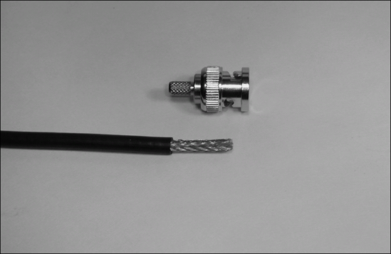
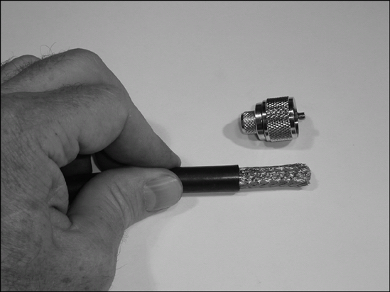
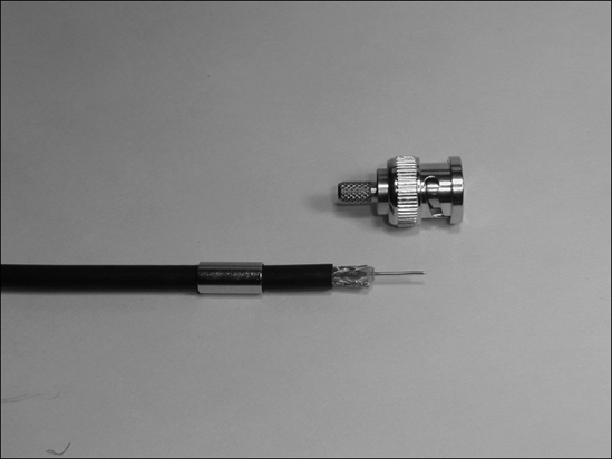
If you are using a coax stripping tool, use it to remove the jacket, braid and center insulator in a single operation and proceed to Step 5. Otherwise, use a sharp knife or razor blade to score and remove the cable jacket so that the shield braid is exposed according to the assembly instructions. If you don't have assembly instructions, remove the jacket for a distance equal to the inner base of the connector's insulator to the end of the crimping surface. (¾" for the connector shown in this sequence of figures.) Be careful to avoid nicking the braid where the jacket is removed.
Use sharp wire cutters (or a very sharp knife or razor blade) to remove part of the exposed braid according to the assembly instructions, leaving the same length of braid as the crimping surface. On the connector shown, 5/16" of braid should be left.
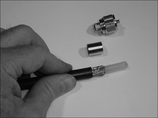
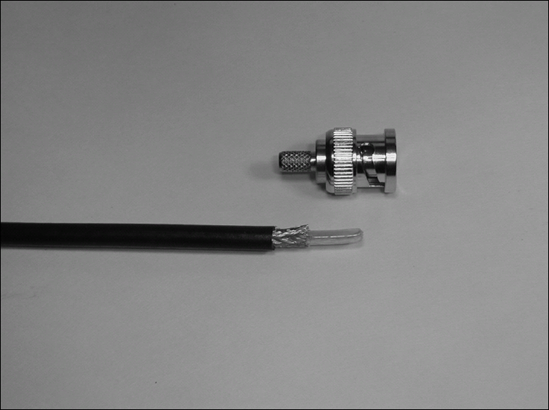
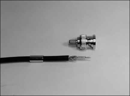
Slide the crimping ring (also called a "ferrule") onto the cable. Score the exposed center insulator according to the assembly instructions and remove it. If you don't have assembly instructions, remove the center insulation, leaving 1/16" extending beyond the end of the braid.
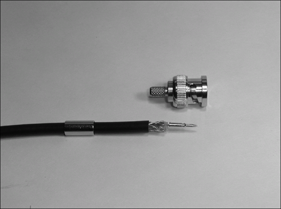
Slide the connector's center pin onto the exposed center conductor. If it does not reach the center insulation, trim the center conductor a little and try again.
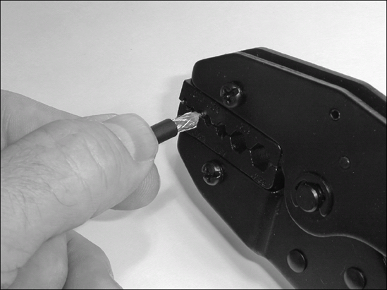
With the center pin resting on the center insulation, insert the pin into the crimper.
Crimp the center pin onto the center conductor. Make a close visual inspection to be sure the crimp is solid and that the pin isn't bent.
Slide the body of the connector over the pin and onto the cable. The inner crimping surface should slide under the exposed braid. Make sure none of the fine braid wires can make a short circuit to the center pin. The center pin should extend just to the forward surface of the connector. There may be a slight snap or click as the cable reaches full insertion. (It is not uncommon to have to remove a small additional amount of jacket to allow the cable to be fully inserted into the body of the connector.)
Slide the crimping ring forward until it contacts the rear of the connector body.
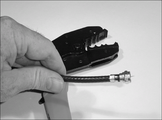
Place the entire connector assembly in the appropriate hole of the coax crimper's jaws so the crimp ring is centered within the hole. Don't let the cable slide back out of the connector — keep it seated firmly in the connector!
Squeeze the handles of the coax crimper evenly and firmly until the ratchet is released. Remove the connector from the crimper.
Use a multimeter to check the resistance between the center pin and the shell — it should show an open circuit. If it doesn't, you'll have to cut off the connector and try again!
Repeat Steps 1 through 6 if you're making a jumper with connectors on each end.
Note
If your cable fails to get a signal from one end to the other and the multimeter doesn't show a short circuit, the problem may be with the center pin. If the cable worked a bit loose from the connector before crimping, the center pin may be too deep in the connector to make contact with the mating receptacle. You'll have to install a new connector to correct the problem.
Tip
There's a lot more information about how to install and operate scanners and external antennas for them in the author's Two-Way Radios and Scanners For Dummies, published by Wiley Publishing, Inc.
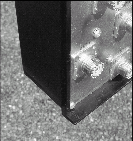
Even if you install a connector perfectly, after it gets exposed to the weather, water will infiltrate the smallest cracks and crannies. Soon the connection will become intermittent or worse! That's why this task shows you how to weatherproof a Type F or UHF connector installed at an antenna or at an connection panel.
Type F and UHF connectors are suited for outside use. BNC connectors are not — and should be avoided in exposed applications.
Put a very small amount of anti-oxidation compound on the threads of the receptacle connector (not on the cable plug connector). In addition to preventing water from getting in via capillary action, the compound also resists corrosion and makes the connector much easier to get off later. The compound is the smear of dark material at the top of the connector — it doesn't take much!
Put another small amount of compound on the center pin or center conductor of the cable's plug connector. Seat the plug in the receptacle and twist it back and forth a few times to smear the compound out around the pin. There should be no compound bridging the space between the center pin or conductor and the connector shell. If there is, remove the connector, wipe it clean, and start over.
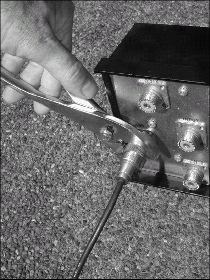
Tighten the connector shell finger-tight and be sure the connectors are firmly seated. Use the pliers to tighten the shell another ⅛ to ¼ turn. This would be a good time to check and make sure the system is working properly before you waterproof the connection.
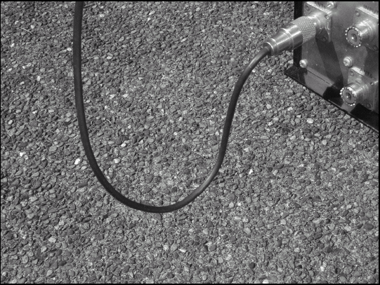
If the connection is horizontal and at the low point of the cable (such as an antenna cable coming down to a connection into your house), add a drip loop to the cable before you waterproof the connector. Any water running down the cable will drip off at the low point of the drip loop instead of being channeled directly into the connector!
If the connector has a big difference in diameters (50% or more) between the connector and the crimp or cable, This could make it difficult to get a smooth wrap, free wrinkles or gaps. Build up the smaller diameter by wrapping several times with tape. This will help make a smooth wrap.
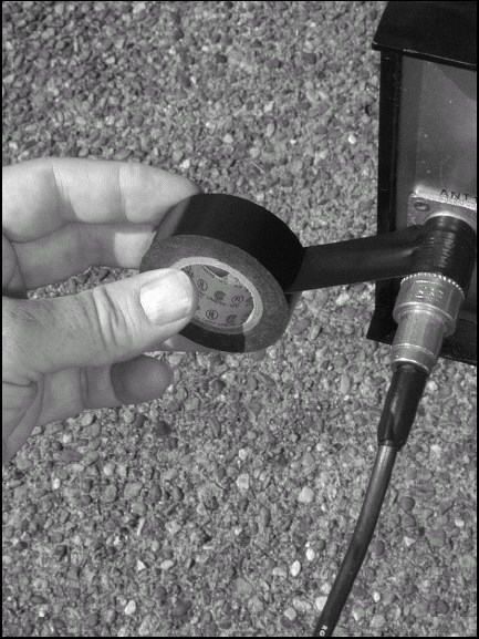
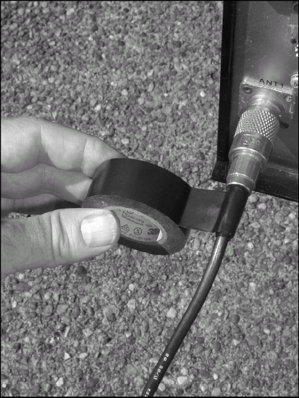
Begin where the threaded shell of the connector is attached to the receptacle. Start the wrap as far forward on the connector as possible. Wrap the electrical tape twice around this point and begin wrapping toward the rear of the connector with at least 50 percent overlap at each turn. This may be difficult in close quarters, so use a screwdriver or pencil to ease the tape into place. Use your fingers to press the tape into place.
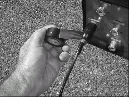
Continue wrapping along the connector until you reach a point an inch or two behind the connector. At changes in connector diameter, give the tape plenty of overlap and press it into place with your fingers (on the non-sticky side only!) to minimize the number and size of wrinkles and folds.
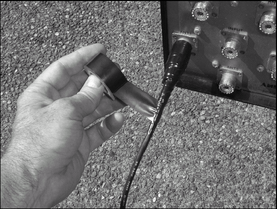
At the end of the wrap, reverse course and wrap all the way back to the point at which you begun in Step 6. If the wrap seems wrinkled or it was difficult to seat the tape smoothly all the way around the connector, cut a short piece of tape and wrap one or two more times around the connector where the wrap ends.
Warning
It's not necessary (or even desirable) to pull the tape taut as you wrap! Good quality tape has plenty of adhesive and will seal just fine with little tension. Pulling on the tape as you wrap will cause it to creep as the plastic exerts tension on the adhesive over time. Just get the tape in place and snug.
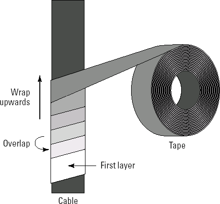
If the connection is vertically oriented, make your final wrap from the bottom up. As with shingles on a roof, the overlap will shed upwards water down the cable and away from the connector. The opposite (wrapping top to bottom) captures water instead!
When you have finished the wrap, cut the tape end and press it firmly into place.
Warning
Don't pull on the tape until it breaks as a way of ending the wrap; remember the earlier caution about creeping tape. At the end of a wrap, creep leads to flagging where the tape's end eventually comes loose and waves around in the breeze. (Oh, say, can you see ...?)