Lots of electronic stuff is powered from good old wall-socket AC voltage. That means lots of cords and connectors that can break or wear out or that have to be installed in new projects. This chapter shows you how to perform three common tasks for repair, maintenance, or new projects.
The goal of this first section is to teach you the rules of the road for AC wiring. It's not meant to frighten you but to give you the information to do the job safely and with confidence.
Note: This book does not cover household AC wiring, such as running cable for outlets and circuit breakers. If you have questions about performing this type of wiring, consult an electrician or other reliable electrical reference.
Warning
It's important to do AC wiring properly because AC power can supply a whole lot of energy. Faulty AC wiring — in the wall or in equipment — is a leading cause of fires. Do not cut corners on any wiring connected to the AC line! DO take your time and do the job right. It rarely takes much longer to use proper techniques, and whatever additional expense is incurred is cheap compared to the potential damage.
Warning
While you can use just about any old wire and components for the low-voltage DC part of electronics, the same is not true of wiring or components connected to the AC line. The insulation of wire used for AC wiring should be at least 600V. Voltage ratings for components connected to 120V circuits should be 180V or higher. Electronic components of all sorts should be line-rated and carry an Underwriters Laboratories (UL) or other safety marking. If you're in doubt, check with the product vendor.
When you're working with AC line cords or power cords, make an extra effort to be sure you're following the right color codes and wiring conventions. To do so, you'll need to know what they are! First, some definitions:
AC wiring in the home consists of three wires: hot, neutral, and a safety ground (or just "ground").
Hot: The wire that supplies current from the power source.
Neutral: The wire through which current returns to the power source.
Safety ground: The wire connected to the Earth. Neutral and safety ground are connected together at the main circuit breaker box. The metal chassis (a framework or enclosure) of equipment or appliances should be connected to the safety ground wire.
A color code is used to allow power wiring to be done correctly without having to use test equipment. By following the AC-wiring color code strictly and without exception, your wiring will be safe and correct. The color code for 120V household wiring is as follows:
Hot: Black (terminals on plugs and sockets are gold or brass-colored).
Neutral: White (terminals on plugs and sockets are silver or white).
Ground: Bare or green (terminals on plugs and sockets are green).
(For color codes on 240V (and higher-voltage) circuits and cords, consult a book about household AC wiring.)
2-wire power cords also have a hot-neutral wiring standard. You may have noticed that on 2-prong plugs, one prong (or blade) is wider than the other so that the plug can only be inserted into the socket in one orientation. These are called polarized plugs; the wider prong is connected to neutral. In addition, on 2-conductor wire (or zip cord), the insulation on one wire is smooth (this is the hot wire) and the other ribbed (this is the neutral). Zip cord gets its name because the two wires can be easily pulled apart like a zipper.
Warning
Power and extension cords can be a major safety hazard if used improperly. Never use extension cords with non-polarized plugs or cords with broken-off ground pins. Never break off the ground pin on an AC power plug. If necessary, use a 3-wire-to-2-wire ground adapter (sometimes referred to as a cheater) — and if possible, connect that adapter's ground terminal to the outlet's faceplate mounting screw (which should be connected to ground).
Wire is also limited in the amount of current it can carry without overheating. If too much current flows in the wire, it will get hot enough to melt its insulation or start a fire. This is caused by the wire's resistance to current. Thicker wire has lower resistance and can carry higher currents. Be sure to use wire that's heavy enough to carry the current you're using, as shown in Table 9-1.
Tip
Wire thickness is measured as a gauge — a set of numbers with each number indicating a specific thickness. The U.S. standard for gauges is AWG (American Wire Gauge). Wire gets thicker as gauge gets smaller. For example, 8-gauge wire is thicker than 12-gauge.
Table 9-1. Current-capacity of common wire gauges
Gauge (AWG) | Current (Amps) |
|---|---|
24 | 2.1 |
22 | 5.0 |
20 | 7.5 |
18 | 10 |
16 | 13 |
14 | 17 |
12 | 23 |
10 | 33 |
Table 9-1 contains information from Reference Data for Engineers: Radio, Electronics, Computer and Communications, 7th Ed.
You just completed a motorized corn-on-the-cob shucker and it works great! But you have to be able to turn it on and off, don't you? You can find the perfect solution in your local hardware store: an in-line switch that you install in the power cord between the motor and the wall socket! In this task, I walk you through the steps to make installation easy and have the final product look great.
There are actually two kinds of in-line switches for power cords. This task uses the big kind — about the size of an egg. It fits power cords up to those with three 12 gauge wires, can switch several amps of current, and has a sturdy switch that snaps on and off. The small kind is made for 2-wire power cords and only handles light loads, such as table lamps. If you learn how to install the big version, the small version will be easy. Just be sure to choose a switch that's rated to handle the current consumed by whatever it's controlling.
Tip
In AC power circuits, switches and fuses are always installed in the hot line, not the neutral. The hot wire is the source of power, so you must interrupt power in the hot wire when turning the device on and off. Switching or fusing the neutral leaves the hot wire connected to the equipment — a definite safety hazard.
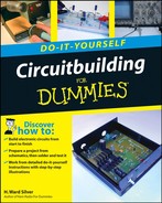
Take the switch apart by loosening the screws. Place the screws, nuts (if any), and cover (the part of the shell without any switch parts in it) in a can or box for safekeeping until you're ready to reassemble the switch. Be careful not to lose the nuts as they often lodge in the cover or switch body. The exposed switch will probably have a little grease on some of its parts—don't wipe it off!
Read the instructions that come with the switch. The following instructions apply to most switches, but you might have to modify them a little for your particular model.
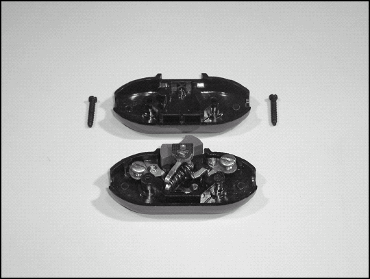
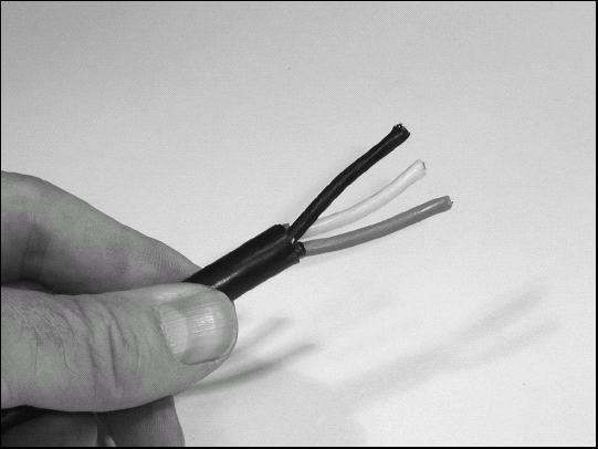
Find the point in the power cord at which you want to install the switch. Remove a length of the jacket equal to the length of the switch minus ¼″. To remove the jacket without nicking the inner wire insulation or strands, use a knife to score the jacket until it parts when the power cable is bent at the cut. Make a shallow cut along the section of jacket to be removed and peel the jacket apart so that it can be removed. Untwist the cord so that the wires can be easily separated. Remove any string or fiber filler material from the exposed area.
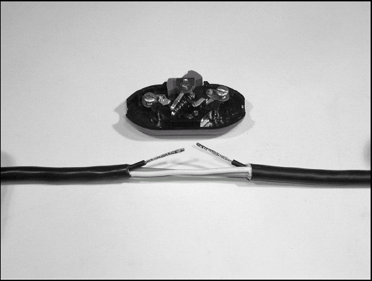
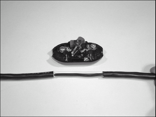
Cut the hot (black) wire in the middle of the exposed area. Strip the black wires so that only ¼″ of insulation is left on the wire as it exits the jacket.
Tip
If you're installing a small switch on 2-wire zip cord, the hot wire is the one with the smooth (non-ribbed) insulation.
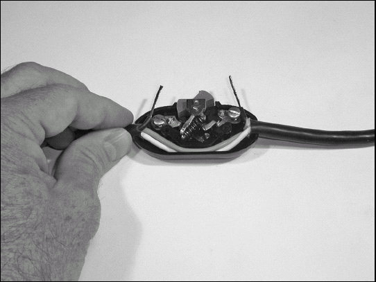
Lay the entire cord in the body of the switch so the neutral (white) and ground (green) wires are in the groove bypassing the switch.
Loosen the connection screws of the switch so there is plenty of room for the wire, but don't remove them entirely. If the screw comes out, reinsert it.
Wrap the stripped ends of the hot wires clockwise three-quarters of the way around the screws. Don't wrap the wire all the way around the screw — and definitely not more than once. The wrap should be clockwise so that as the screw is tightened, it pulls the wire around and under the screw instead of pushing it out.
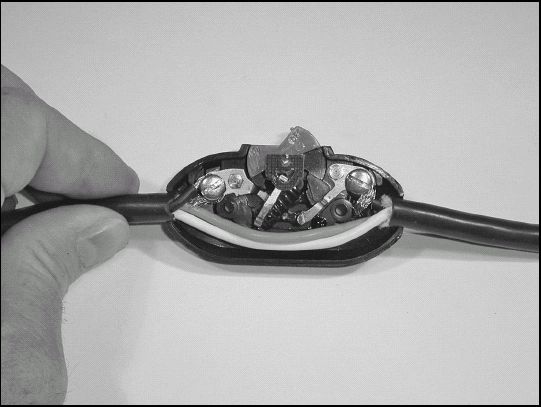
Tighten the screws and trim the excess wire.
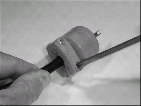
Look closely at the exposed switch body. Next to the holes on either end where the power cord enters the switch, a small rib just inside the hole acts as a strain relief by capturing the power cord jacket when the cover is attached. Push the cord in slightly at each end so the jacket is at least ⅛″ past the ribs.
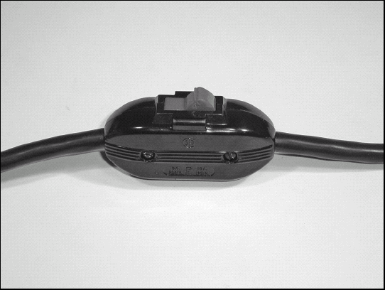
Reattach the switch cover and make sure the individual wires are not exposed at either end of the switch. If they are, remove the cover again and reseat the cord in the hole. Once the cover is attached, you can plug in the cord and try it out!
For any project that brings AC power directly into the equipment case (as opposed to power from an external supply), a fuse is a must — both for safety and to protect the equipment from damage in the event of a short circuit or component failure. Chapter 7 shows how to install an in-line fuse holder in a DC power lead — for AC circuits, however, it's better to use a chassis-mounted fuse holder for safety. In this simple task, you'll learn not only about attaching wires to terminals, but to think about safe ways of dealing with AC power.
Turn on the soldering iron and when it's hot, tin (coat with solder as described in Chapter 2) both terminals of the fuse holder.
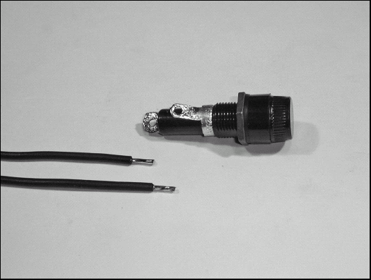
Strip the ends of the wire that will attach to the fuse holder and tin them.
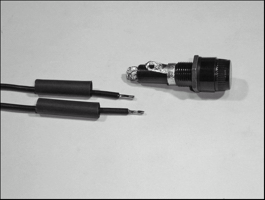
Cut two pieces of heat-shrink tubing about 1" long. The tubing should fit over the fuse holder terminals. Slip the tubing over the wires.
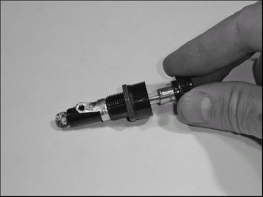
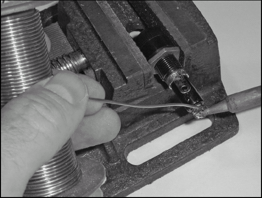
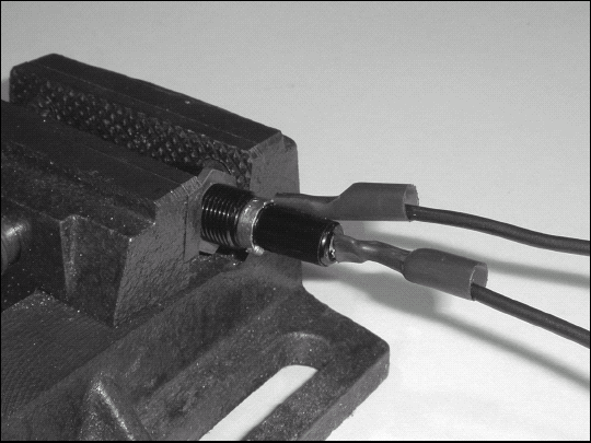
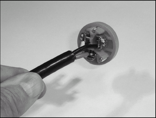
Look carefully at the fuse holder, noting that there is one terminal at the very back (at the left of the figure) and a forward terminal (at the right of the figure) just behind the threaded portion of the body. Place a fuse in the cap of the fuse holder and fully insert it. Now remove the fuse slowly, stopping about halfway out.
If you are installing the fuse holder in a piece of equipment, orient it with the terminals oriented so that it's easy to solder the wires to them. (A vise is used in the figure for the following step so you can see the usual orientation.)
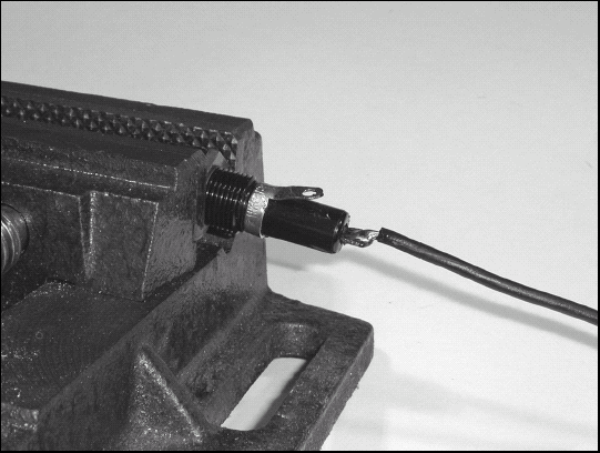
Insert the tinned live wire into the rear terminal of the fuse holder and solder it.
Warning
One end of the fuse cartridge is in the cap, held in your fingers. The other end is halfway into the holder, in contact with the forward terminal — and your fingers are perilously close to the metal end of the fuse! If the hot wire is connected to the forward terminal, it is easy to get shocked when removing the fuse. The hot wire should always be connected to the rear terminal of the fuse holder. In other words, power should flow into the back of the fuse holder and out through the forward terminal so that if the fuse is removed while the equipment is energized, AC voltage is never present on the exposed cap of the fuse holder.
Slide the heat shrink tubing over the terminal and shrink. it onto the terminal. It is OK if the portion over the wire is loose as the goal is to insulate the exposed terminal.
Repeat Steps 6 and 7 for the remaining wire, and then install the fuse.
The simple task of replacing or adding an AC plug to a power cord is another seemingly-trivial task often performed poorly by home technicians. This task shows you techniques for working with AC power connections — and gives you some practice at using them. You'll also reinforce your knowledge of color codes.
Before beginning, make sure you've chosen the right size plug (and cord or cable) for the job. Most 3-prong AC sockets and plugs are not designed to carry more than 20 amps. If you're going to be supplying more power than that, you should use a high-current plug and socket. Plugs and sockets for ac power have a "NEMA" (National Electrical Manufacturers Association) rating number that shows what type they are and how much current and voltage they can safely carry. The rating is also stamped into or molded in the body of the plug or socket. For more information, the Wikipedia entry on NEMA connectors (http://en.wikipedia.org/wiki/NEMA_connector) will provide all the information you need.
Tip
Heat is the enemy of electrical connections. Run your vacuum cleaner for a while and then unplug the cord, feel the AC plug, and feel the socket: They're warm! The heat comes from electrical resistance in the connections of the wires to the plug and socket contacts and in the contacts themselves. The higher the current, the higher the heat given off. If overloaded, contacts can get hot enough to melt or char the insulation around them. The metal of the contacts can oxidize, further increasing resistance and heat. Overloaded contacts will quickly fail, creating a significant fire hazard. Use properly rated cable and plugs to avoid this very real hazard.
Tip
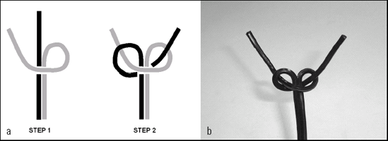
How do you stop zip cord from unzipping itself? Zip cord, used for 2-wire power cords and speaker cables (among other uses), is made so the conductors will separate easily and cleanly. Sometimes they separate a bit too easily. To hold the wires together, learn the Western Union knot shown in Figure 9-1. With about 2″ of the cord unzipped, loop one so the wire comes back across the cord on the side facing you as shown in Step 1. Loop the other wire around the free end of the first, behind the cord, and back through the loop of the first wire as in Step 2. Each wire is then captured in the loop formed by the other wire. Gently tighten — it's not necessary or desirable to make the knot really tight — and your unzipping worries are over!
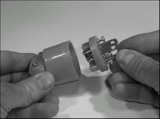
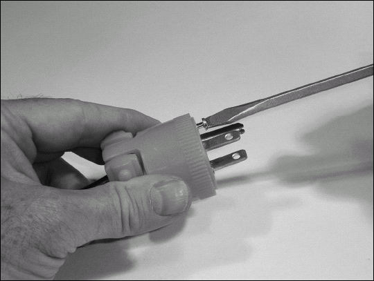
Separate the shell of the plug from the contact assembly by loosening the screws in the front of the plug body next to the prongs. (Your plug may vary from the one shown in the figure.)
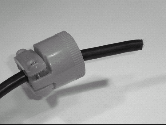
Slide the shell onto the power cord. You may have to loosen the screws on the strain-relief clamp that holds the cord. It's not necessary to completely disassemble the clamp. (Some plugs have metal clamps, or the clamp may be built into the shell of the plug.)
Remove 1" to 1½″ of the power-cord jacket. When the plug is completely assembled, the strain-relief clamp should make contact only with the jacket and none of the inner wires should be exposed. Check the amount of jacket to be removed by sliding the plug parts together and taking a look. (Your plug may have come with instructions that specify how much jacket to remove.) Avoid nicking the inner wires or their insulation by scoring the jacket and flexing the cord until the jacket breaks away cleanly. Trim off and discard any string or fiber filler.
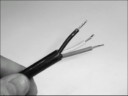
Strip ½″ of the insulation from each wire. Twist the strands lightly to keep them together, following the manufacturer's direction of twist. Inspect the wires to be sure that they are shiny and not corroded or oxidized. If they are, cut off 6″ of cable and go back to Step 3. The wires must be clean and bright to minimize resistance at the connection.
Loosen the terminal screws on the plug's contact assembly. Do not remove the screws, just loosen them enough so the stripped wires can be inserted.
Arrange the wires so that they line up with the correct terminals; hot (gold), neutral (silver), and safety ground (green). If your plug has screw terminals, one terminal at a time, wrap the stripped end of the wire clockwise around the screw just ¾ of a turn. If instead your plug has clamps that capture the wire, insert the stripped portion of the wire into the clamp (no insulation should be in the clamp) and tighten.
Don't wrap the wire all the way around the screw — and definitely not more than once. The wrap should be clockwise so that as the screw is tightened, it pulls the wire around and under the screw instead of pushing it out.
Slide the shell of the plug back onto the contact assembly and attach it.
Tighten the strain relief clamp onto the jacket of the cord. If you cut the jacket a little bit long (less than ¼″), you can push the cord into the plug and then tighten the clamp. More than ¼″ and you'll need to disassemble the plug, cut the wires a bit shorter, and try again. Don't tighten the clamp so much that it bites into the jacket. It should be tight enough that the cord doesn't move inside the connector when you push or pull on the cord.
Power cords get damaged from all sorts of things; over-enthusiastic weed-whacking or hedge-trimming, forgetting that the car's battery warmer was still plugged in, even being chewed up by dogs and rodents! New cords aren't cheap as any hardware store patron knows. This task shows you how to make that cord almost as good as new for the cost of a little time and effort.
This task shows how to repair a 3-wire power cord but the same techniques apply to their smaller 2-wire power cord cousins.
Trim the separated ends of the cord and remove any frayed, wet, or oxidized wire.
Cut a 6″ piece of heat-shrink tubing with a diameter 50% greater than the cord's jacket.
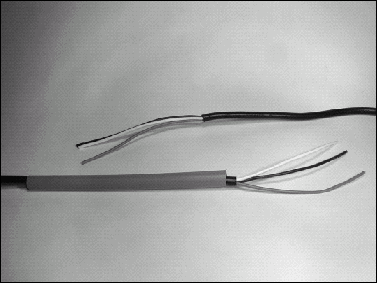
Trim 4″ of jacket from each piece of cord. Avoid nicking the inner wires or their insulation by scoring the jacket and flexing the cord until the jacket breaks away cleanly. Untwist and straighten each wire. Remove any string or filler material. Slide the heat shrink tubing over either piece of cord.
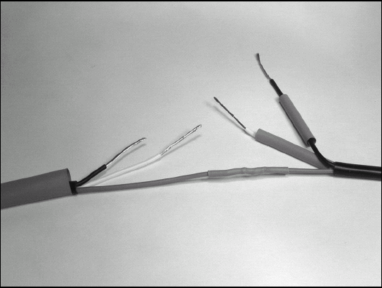
To separate the splices of each individual wire, perform the splice at a different point on each pair of wires. On the left-hand piece of cord, cut the wires as follows: hot — 2″ from the jacket, neutral — 3″ from the jacket, ground — do not cut.
On the right-hand piece of cord, cut the wires as follows:
Hot — do not cut
Neutral — 3″ from jacket
Ground — 2″ from jacket
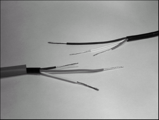
Strip each wire 1″. You can see in the figure that each splice will be 1" apart, keeping plenty of insulation between the bare wires.
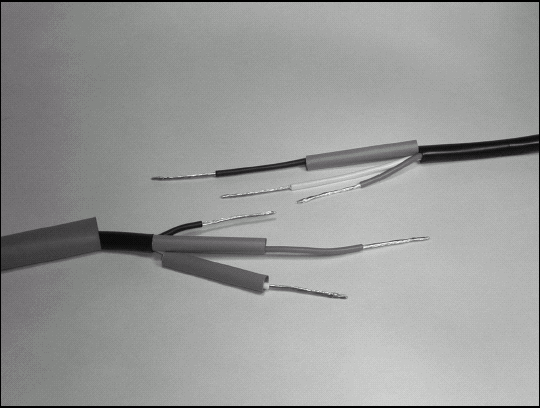
Cut three 1½″ pieces of ¼″ diameter heat shrink tubing. Slip one piece over each wire.
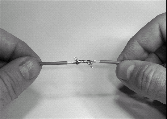
Starting with the neutral wire (it will be the easiest since both pieces are longer), cross the stripped wires at their midpoint and twist each around the other in opposite directions. This is a "Western Union" splice, originally invented for repairing telegraph lines in the mid-1800s! Continue twisting until the wires are snugly wrapped around each other.
Solder the wires together, center the heat-shrink tubing over the splice and shrink it.
Repeat Steps 6 and 7 for the hot and ground wires.
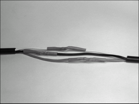
Center the large piece of heat-shrink tubing over the entire splice and shrink it.
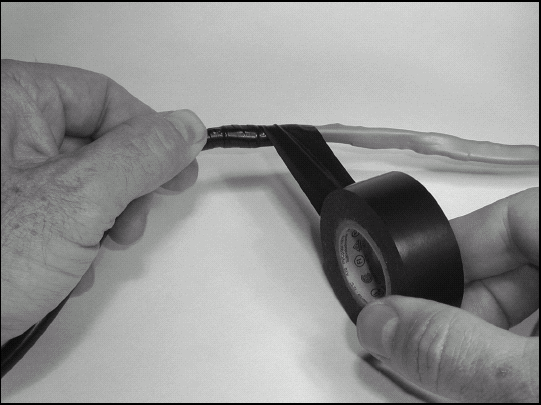
Wrap the splice with good-quality electrical tape (Scotch 33+ and Scotch 88 are excellent choices) twice, once in each direction, overlapping each successive wrap at least 50%. At the end of the wrap, cut the tape and press it into place.
Do not pull the tape apart; that causes the top layer to begin to separate. Eventually pulled-apart tape comes completely loose (flagging).