
Chapter 10. Cisco SD-WAN Security
This chapter covers the following topics:
Cisco SD-WAN Security: Why and What: This section covers what SD-WAN security is and why it is relevant to an organization.
Application-Aware Enterprise Firewall: This section of the chapter covers the concepts and configuration of the Application-Aware Enterprise Firewall.
Intrusion Detection and Prevention: This section of the chapter covers the concepts and configuration of the intrusion prevention and detection engine.
URL Filtering: This section of the chapter covers the concepts and configuration of the URL Filtering engine.
Advanced Malware Protection and Threat Grid: This section of the chapter covers the concepts and configuration of the Advanced Malware Protection engine and Threat Grid cloud.
DNS Web Layer Security: This section of the chapter covers the concepts and configuration of DNS Web Layer security.
Cloud Security: This section of the chapter covers the concepts and configuration of third-party cloud security.
vManage Authentication and Authorization: This section of the chapter covers the concepts and configuration of vManage authentication and authorization.
Cisco SD-WAN Security: Why and What
With the advent of many business-critical applications migrating to the cloud and the rapid adoption of Internet circuits as a business-grade transport, a new and more optimal way to consume applications is being leveraged. Direct Internet Access (DIA) allows end users to reach cloud applications and resources in a more optimal fashion by connecting to the closest and highest-performing point of presence. Most cloud application providers highly recommend not backhauling this traffic through a remote data center or hub but instead going directly from the branch through DIA to the application—leveraging DNS and geo-location services for the best possible performance. In addition, organizations are realizing that they can leverage these same Internet circuits as a means to offload guest traffic to the Internet directly instead of using up WAN and data center resources that would be better used for business-critical applications. Coupled with Cisco SD-WAN Application-Aware Routing and visibility, you have a solution that makes sense for the majority of organizations across most verticals.
Realistically, however, we cannot ignore the security implications of moving the Internet edge to the branch. The DIA model—where Internet access is distributed across many branches, unsecured guest users are allowed Internet access directly, and payment card infrastructure is exposed to these new access models—increases the attack surface of the network. The proliferation of highly publicized massive data breaches has made security compliance, particularly PCI compliance, a critical task for almost every organization. The threat landscape is wide and includes cyber warfare, ransomware, and targeted attacks. These threats can be manifested in many ways (such as security bugs and vulnerabilities, malware, denial of service attacks, botnets, and so on). It is important to note that security threats can come from both inside the network and from outside the network, so all attack vectors must be considered. Figure 10-1 depicts the ever-growing threat surface.
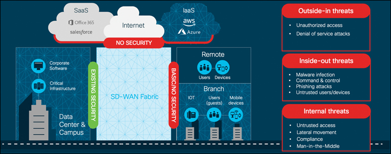
Figure 10-1 Threat Surface
It is critical that the appropriate security mechanisms, such as firewalling, intrusion prevention, URL filtering, and malware protection, are leveraged by the branch in order to prevent, detect, and protect the network from all types of threats. The question facing network architects now is how should security services be consumed by the branches? One way to consume Cisco SD-WAN security is by leveraging Cisco’s integrated security applications within a rich portfolio of powerful WAN Edge routers, such as the ISR4000 series. On top of the native application-aware stateful firewall, these WAN Edge routers have the capability of dedicating compute resources to application service containers running within IOS-XE to enable in-line IDS/IPS, URL filtering, and Advanced Malware Protection (AMP). The enablement, visibility, and reporting of these integrated security applications are accomplished through a unified management console, Cisco vManage. While this chapter focuses mainly on integrated security at the branch, Cisco SD-WAN security can also be consumed through cloud services or through regional hubs where VNF-based security chains may be leveraged or robust security stacks may already exist. In the end, the appropriate security architecture depends on the organization’s technical and business requirements. Figure 10-2 illustrates some of the security deployment models that organizations can choose to deploy.
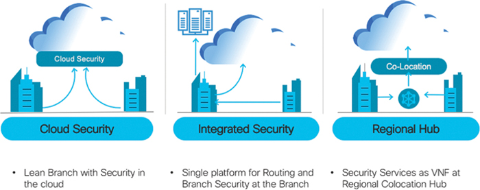
Figure 10-2 Security Deployment Models
Here are some benefits of the Cisco SD-WAN Security suite:
Simple and automated security solution: The intent-based workflow is designed for ease of configuration and deployment of the SD-WAN security solution. The workflow allows you to leverage templates in order to include all of the relevant security capabilities and deploy the policy to multiple devices at the same time.
Comprehensive SD-WAN security: With security capabilities such as Application-Aware Enterprise Firewall and IPS enabled on your WAN Edge device, you can do the following:
Restrict access to certain Internet destinations for remote employees and guests, with improved application experience.
Protect the internal network from malware and/or malicious content in real time.
Incur no additional cost, as deploying the Cisco SD-WAN security solution eliminates the need to deploy any additional equipment within your SD-WAN network to enable security features.
Centralized management: Deploy, troubleshoot, and monitor the SD-WAN overlay solution with security capabilities across the WAN Edge devices centrally via the Cisco vManage GUI.
As briefly mentioned previously, Cisco SD-WAN security features are centrally configured via vManage in the security section through simple guided workflows. The guided workflow can assist the network operator in building security policy based on well-known use cases such as Compliance, Guest Access, Direct Cloud Access, and Direct Internet Access or based on a custom use case. Figure 10-3 shows the workflow and some of the options that can be configured. The security policy is then assigned to the desired branch through the attached branch template.

Figure 10-3 Security Policy Workflow
Application-Aware Enterprise Firewall
One of the most basic yet crucial forms of security at the branch is firewalling. A proper firewall provides protection of stateful TCP sessions, enables logging, and ensures that a zero-trust domain is implemented between segments in the network. Traditional branch firewall design involves deploying the appliance in either in-line Layer 3 mode or transparent Layer 2 mode behind (or ahead) of the WAN Edge router. This adds additional complexity to the enterprise branch and creates needless additional administrative overhead in managing the added firewalls. Cisco SD-WAN takes an integrated approach and has implemented a robust Application-Aware Enterprise Firewall directly into the SD-WAN code. The Cisco SD-WAN firewall provides stateful inspection, zone-based policies, and segment awareness. Also, through network-based application recognition, it can classify over 1,400 Layer 7 applications for granular policy control. These applications can be secured based on category or on an individual basis, depending on how the feature is leveraged in the security policy. Because these policies are VPN aware, they can be applied within a zone, between zones on the same WAN Edge router, or between zones across the Cisco SD-WAN fabric. A zone is a grouping of one or more VPNs. Grouping VPNs into zones allows you to establish security boundaries in your overlay network so that you can control the flow of all data traffic that passes between these zones.
Zone configuration consists of the following components:
Source zone is a grouping of VPNs where the data traffic flows originate.
Destination zone is a grouping of VPNs where the data traffic flows terminate.
Firewall policy is a localized security policy that defines the conditions that the originating data traffic flow must match to allow the flow to continue to the destination zone.
Zone pair is a container that associates a source zone with a destination zone and that applies a firewall policy to the traffic that flows between the two zones.
In addition, a self-zone policy exists in order to inspect traffic destined to the WAN Edge router itself, so as to protect from inbound threats, DDoS attacks, and unauthorized access to the WAN Edge router. When combined with other Cisco SD-WAN security features, Application-Aware Enterprise Firewall is an important component of the solution for organizations looking to meet PCI compliance across the enterprise branch footprint. Figure 10-4 provides an overview on the typical zones and traffic flows for an application-aware firewall.
Firewall events and logs can be exported to security information and event management systems through traditional syslog or, for more advanced implementations, via NetFlow v9 to support high-speed logging requirements.
Note
Support for application recognition through firewall policy is currently only available on Cisco IOS-XE SD-WAN software and not Viptela OS. Cisco vEdge and ISR appliances running Viptela OS can still enjoy the benefits of a firewall but must use Layer 3 and Layer 4 criteria to identify traffic.
Through the help of Cisco vManage, implementing a firewall policy at the branch is relatively straightforward. Like all other security features available in Cisco SD-WAN, the first place to start is by navigating to the security section and either building a new security policy (and following the simple workflow to build a firewall policy) or directly navigating to the firewall policy subsection under Custom Options. Figure 10-5 shows the security policy page in vManage. No matter how the firewall policy is configured, it must eventually be tied to an overall security policy, which is then attached to the branch WAN Edge router template.
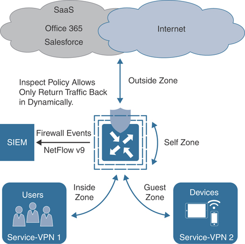
Figure 10-4 Application-Aware Enterprise Firewall
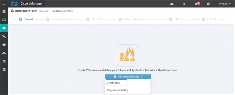
Figure 10-5 Building a Firewall Policy
Enterprise Application-Aware Firewall is a localized security policy that allows stateful inspection of data traffic flows that are matched based on six different criteria available within the vManage security policy dashboard. The match criteria include source data prefix, destination data prefix, source port, destination port, protocol, and application/application family. Traffic flows that originate in a given zone are allowed to proceed to another zone based on the policy match and action criteria set between the two zones.
Within a given firewall policy, accepted matching flows can be subjected to the following three actions:
Inspect: When the action is set to Inspect, the Enterprise Application-Aware Firewall tracks the state of the flows and creates sessions. Since it maintains the state of the flows, the return traffic is allowed and there is no need to configure a separate policy to allow the response traffic.
Pass: This action allows the router to forward the traffic from one zone to another zone. The Pass action does not track the state of the flows. In other words, the firewall does not create sessions when the action is set to Pass. The Pass action allows the traffic to flow in only one direction. You must have a corresponding policy to allow the response traffic.
Drop: When the action is set to Drop and packets match against the set match parameters, that packet will be dropped.
Note
When leveraging application recognition for match criteria, the Inspect action will be equivalent to a Drop action.
Based on the flow of traffic between zones, the Enterprise Application-Aware Firewall is further divided into intra-zone-based security and inter-zone-based security.
The diagram in Figure 10-6 depicts an intra-zone security use case where hosts within the same zone on the same WAN Edge router can be secured with a firewall policy, while the same policy can also secure hosts across the fabric on the same zone. For the firewall policy rule to be impactful, traffic must ingress and egress the WAN Edge router and should not be bypassed via a downstream Layer 3 device.
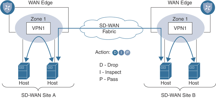
Figure 10-6 Intra-Zone Firewall Application
The diagram in Figure 10-7 depicts an inter-zone security use case where hosts on different zones within the same WAN Edge router can be secured with a firewall policy, while the same policy can also secure hosts across the fabric on different zones. For inter-zone connectivity to occur, a vSmart policy that leaks routes between VPNs must first be configured and applied. This is called an extranet policy and leverages the “Export to” route-based control policy sequence.
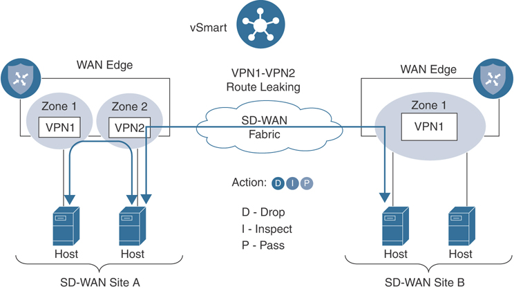
Figure 10-7 Inter-Zone Firewall Application
The following is a summary of steps required to configure a firewall policy in Cisco SD-WAN:
Step 1. Create a new firewall policy. Name and describe the policy.
Step 2. Configure zones. Create your source and destination zones. Today, zones are equivalent to SD-WAN VPNs.
Step 3. Apply zone pairs. Group the source and destination zones into a zone pair to define traffic direction. The policy sequences will be applied to this zone pair.
Step 4. Configure a default action. This is the action that will take place if a sequence match is not found. Drop, Inspect, and Pass are valid options.
Step 5. Configure sequence rules. Match traffic using Layer 3–4 information (such as source data prefix lists, source ports, destination data prefix lists, and so on) or by matching on application category or name.
Once a firewall policy is created, the zones and zone pairs are then created and applied. Figure 10-8 shows the zone and zone-pair configuration in vManage.
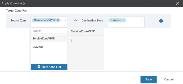
Figure 10-8 Zone and Zone-Pair Configuration
After the zones and zone pairs are configured, you will need to build the sequence rules next. You can also specify a default action in the sequence rule configuration shown in Figure 10-9.
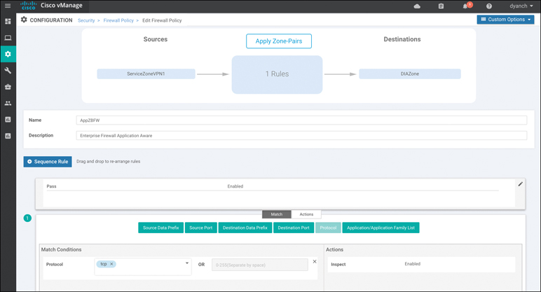
Figure 10-9 Sequence Rule Configuration
Once all the desired sequence rules are configured, the firewall policy can be saved and other security functions such as IPS/IDS can be enabled through additional workflow tasks. Advanced firewall features such as high-speed logging, policy bypass for direct Internet 358access, TCP SYN flood limiting, and audit trails for inspection logging can be enabled at the end of the workflow in the Additional Policy Settings section, as shown in Figure 10-10.

Figure 10-10 Advanced Firewall Features
The security policy that has the newly built firewall policy can then be referenced in a template that is attached to a branch WAN Edge router under the Additional Templates section. Figure 10-11 shows a summary of how a firewall policy is built, attached to a security policy, and applied to a device template for activation.
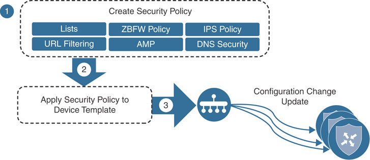
Figure 10-11 Security Policy Application
Figure 10-12 demonstrates how to attach a security policy to a device template under the Additional Templates section.
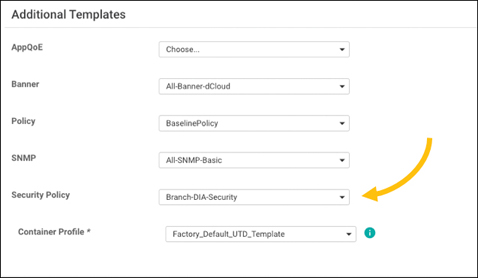
Figure 10-12 Security Policy in Template
Note
The factory default Security App Hosting template referenced under the container profile section can be selected if no SD-WAN Security feature using application service containers is referenced in the security policy. Cisco Application-Aware Enterprise Firewall does not utilize application service containers.
Monitoring of the Application-Aware Enterprise Firewall statistics can be done through the main security dashboard or, for more complete details, through the firewall section of the device dashboard. Both screens are able to show a historical view of inspected/dropped sessions, though the dashboard view can display the actual firewall policy being hit for more granular reporting, as shown in Figure 10-13.
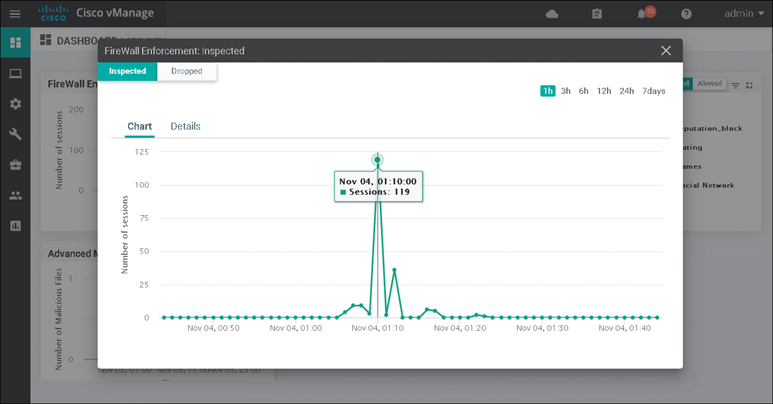
Figure 10-13 Security Dashboard
The firewall device dashboard is where traffic statistics can be monitored, along with viewing what policies are applied (and their associated zones). Figure 10-14 shows the Firewall Policy Monitor page in vManage.
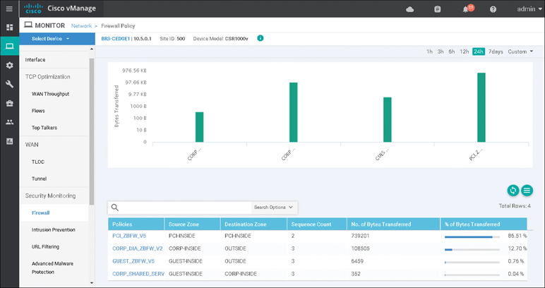
Figure 10-14 Firewall Device Dashboard
All ISR, ASR, and CSR platforms that support IOS-XE SD-WAN code are capable of running the Application-Aware Enterprise Firewall functionality.
Please refer to the Cisco SD-WAN Security Configuration guide published on the Cisco documentation site for additional deployment details.
Note
You can gather more detailed firewall statistics through the Real Time section of the device dashboard or via CLI show command sets.
Intrusion Detection and Prevention
Intrusion detection and prevention (IDS/IPS) is another important key to branch security and a component of the Cisco SD-WAN security suite. An IDS/IPS can inspect traffic in real time in order to detect and prevent cyberattacks by comparing the application behavior against a known database of threat signatures. Once detected, an IDS/IPS can notify the network operator through syslog events and dashboard alerts as well as stop the attack by blocking the threatening traffic flow. IDS/IPS is enabled through the use of IOS-XE application service container technology. Application service containers allow the network operator to leverage CPU cores and memory on an ISR to host virtual machines directly in IOS-XE and redirect application flows through the container for processing.
The two VM types used by service containers are called Kernel Virtual Machines (KVM) and Linux Virtual Containers (LxC). These two container types differ mainly in how tightly they are coupled to the Linux kernel used in most network operating systems, such as IOS XE. LxC containers use many of the kernel resources of the host, while KVM containers have their own independent kernel. This means that a KVM can be slightly more portable than an LxC container, while an LxC might have a slight performance edge over a KVM. To the end user, however, the container type is completely invisible since all of this is determined by the service container developer. Cisco SD-WAN security leverages LxC containers.
Figure 10-15 shows an example of the application service container architecture in IOS-XE.
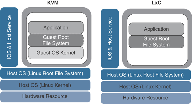
Figure 10-15 Application Service Container Architecture
Cisco SD-WAN IDS/IPS runs Snort, the most widely deployed intrusion prevention engine in the world, and leverages dynamic signature updates published by Cisco Talos. The Cisco Talos Intelligence Group is one of the largest commercial threat intelligence teams in the world and is composed of world-class researchers, analysts, and engineers. These teams are supported by unrivaled telemetry and sophisticated systems to create accurate, rapid, and actionable threat intelligence for Cisco customers, products, and services. With Talos, the IDS/IPS system can provide real-time traffic analysis to reliably protect the branch from thousands of threats on a daily basis. Cisco vManage connects to the Talos signature database and downloads the signatures on a configurable periodic or on-demand basis and pushes them down into the branch WAN Edge routers without user intervention. Signatures are a set of rules that an IDS and an IPS use to detect typical intrusive activity.
The two methods for signature update include automatic IPS signature update via vManage and manual IPS signature update using CLI commands available on the WAN Edge device. When a new signature package is updated, the Snort engine will restart and traffic may be interrupted or bypass inspection for a short period (depending on the data plane fail-open/fail-close configuration).
Note
Currently, Cisco does not support manual IPS signature set upload within the vManage virtual-image repository. If you encounter issues performing an automatic signature update from vManage, update the signature manually from the WAN Edge device.
Like all other security features available in Cisco SD-WAN, the first place to start is to navigate to the security section and either build a new security policy (and follow the simple workflow to build an IDS/IPS policy) or directly navigate to the IDS/IPS policy subsection under Custom Options. No matter how the IDS/IPS policy is configured, it must eventually be tied to an overall security policy (which is then attached to the branch WAN Edge router template).
Note
To support IDS/IPS functionality, an ISR must be configured with a minimum of 8GB of DRAM and 8GB of system flash.
The following is a summary of steps required to configure an IDS/IPS policy in Cisco SD-WAN:
Step 1. Create a new IDS/IPS policy. Name the policy.
Step 2. Configure signature set. Specify the desired signature set: Balanced, Connectivity, or Security.
Step 3. Configure the signature whitelist (optional). Specify a list of signature IDs.
Step 4. Configure alerts log level (optional): Specify the alerts log level, from Debug to Emergency.
Step 5. Configure target VPNs. Specify the VPNs to be inspected.
These steps can be accomplished by using the IDS/IPS Policy Workflow in vManage, as shown in Figure 10-16.

Figure 10-16 IDS/IPS Policy Workflow
The IDS/IPS engine allows for the network operator to configure three different signature sets: Balanced, Connectivity, and Security. Each of the signature levels contains a list of security vulnerabilities categorized based on the score assigned using the Common Vulnerability Scoring System (CVSS).
Note that CVSS is a free and open industry standard for assessing the severity of security vulnerabilities.
Here are the three signature levels available within vManage IPS:
Balanced: This is the default signature set, which contains rules that are from the current year and the previous two years. The Balanced signature set is designed to provide protection without a significant effect on system performance.
This signature set is for vulnerabilities with a CVSS score of 9 or greater, and its categories include those listed in Table 10-1.
Table 10-1 Balanced Signature Set
Category |
Definition |
|---|---|
Blacklist |
Rules for URIs, user agents, DNS hostnames, and IP addresses that have been determined to be indicators of malicious activity. |
Exploit-kit |
Rules that are designed to detect exploit kit activity. |
Malware-CNC |
Rules for known malicious command and control activity for identified botnet traffic. These include call home, downloading of dropped files, and exfiltration of data. |
SQL Injection |
Rules that are designed to detect SQL injection attempts. |
Connectivity: This signature set contains rules from the current year and the previous two years for vulnerabilities with a CVSS score of 10. The Connectivity signature set is less restrictive, with better performance, as there are fewer rules attached to this signature level.
Security: This signature set contains rules that are from the current year and the previous three years. With more added rules, this signature level offers more protection, but overall performance of your WAN Edge device may be lower.
This signature set is for vulnerabilities with a CVSS score of 8 or greater, and its categories include those listed in Table 10-2.
Table 10-2 Security Signature Set
Category |
Definition |
|---|---|
App-detect |
Rules that look for and control the traffic of certain applications that generate network activity. |
Blacklist |
Rules for URIs, user agents, DNS hostnames, and IP addresses that have been determined to be indicators of malicious activity. |
Exploit-kit |
Rules that are designed to detect exploit kit activity. |
Malware-CNC |
Rules for known malicious command and control activity for identified botnet traffic. These include call home, downloading of dropped files, and exfiltration of data. |
SQL Injection |
Rules that are designed to detect SQL injection attempts. |
The network operator can also configure a signature whitelist, which provides the opportunity to define a list of signature IDs in the format of GeneratorID:Signature:ID. Any application flow that matches a signature ID defined in the list is ignored and passed through the IDS/IPS engine without action. This is useful for suppressing false indications of an attack with legitimate network traffic.
The Snort engine can operate in either Detection mode, where threats are only detected and logged, or Protection mode, where the engine detects and drops the threat while also providing a log of the event. vManage also provides a multitude of configurable IDS/IPS alert log levels to fit the security requirements of the organization.
Before an IDS/IPS policy can be configured, the network operator must upload a security virtual image to vManage under the software repository section (as discussed previously, this is the LxC container that will host Snort). The security virtual image can be downloaded from the Cisco software portal and is packaged in TAR format. In addition, the network operator’s Cisco CCO username and password must be configured under the vManage Settings, IPS Signature Update section for automatic signature updates to succeed. Figure 10-17 shows the process of uploading a security virtual image to vManage.

Figure 10-17 Security Virtual Image Upload
In addition to uploading the security virtual image, the policy will need to be configured as illustrated in Figure 10-18.

Figure 10-18 IDS/IPS Policy Configuration
Once the IDS/IPS policy options are configured, a target VPN or VPNs must be defined in order for the engine to know which segments on the branch WAN Edge router need application flows redirected through the Snort engine for processing.
In addition to the syslog server configuration, the policy summary section of the workflow allows for the network operator to configure the failure mode of the Snort engine. The Fail-close option drops all IPS/IDS traffic when there is an engine failure or engine reboot. The Fail-open option allows all IPS/IDS traffic when there is an engine failure or engine reboot. The default option is Fail-open.
Figure 10-19 provides a high-level depiction of how application flows are passed through the Snort engine in an ISR.

Figure 10-19 Snort Traffic Engine
Note
If an application service-based security feature has never been enabled on a particular ISR before, a container installation task will automatically begin after the security policy is attached to the branch template. Once this installation is complete, the security policy will be enabled. This task can be monitored for successful completion by navigating to the active task pane at the top right of the Cisco vManage dashboard.
The last step to enable IDS/IPS on a branch WAN Edge router is to attach the IDS/IPS policy to a branch device template.
Note
As a best practice, configure a Security App Hosting template to be referenced under the Container Profile section. The template can retain the default settings.
Monitoring of IDS/IPS statistics can be accessed through the main security dashboard shown in Figure 10-20. For more complete details, you can also monitor IDS/IPS statistics through the Intrusion Prevention section of the device dashboard. The security dashboard screen can show historical top signature hits by count or by severity and even display which remote site is contributing to these hits the most. In addition, this view can provide details around which source and destination IPs and VPNs are involved with the signature hits.
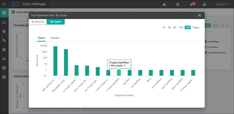
Figure 10-20 IDS/IPS Security Dashboard View
The Intrusion Prevention device dashboard screen also provides a view of signature hits by severity or count, but with more granularity and historical resolution, as shown in Figure 10-21. In addition, this view of the feature can provide the IPS version, when the signatures were last updated, and descriptions of the signatures being hit. From this screen, the network operator can access a hyperlink to learn more about the specific signature being hit in the environment.
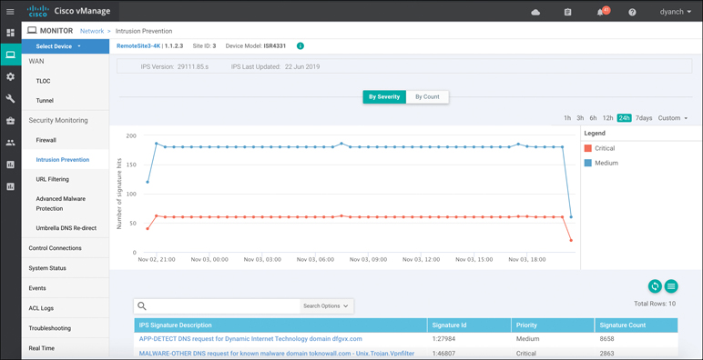
Figure 10-21 IDS/IPS Device Dashboard View
Only ISR and CSR platforms that support IOS-XE SD-WAN code are capable of running the IDS/IPS functionality.
Please refer to the Cisco SD-WAN Security Configuration Guide published on the Cisco documentation site for additional deployment details.
Note
More detailed IPS/IDS statistics can be gathered through the Real Time section of the device dashboard or via CLI show command sets.
URL Filtering
URL Filtering is another Cisco SD-WAN security function that leverages the Snort engine for inspection of HTTP and HTTPS payloads, in order to provide comprehensive web security at the branch. The URL Filtering engine enforces acceptable use controls to block or allow websites. An administrator can choose to permit or deny websites based on 82 different categories, the site’s web reputation score, and a dynamically updated URL database. Custom black and white lists can also be created with customized end-user notifications, in order to bypass the URL Filtering engine for websites that are internal or trusted.
When an end user requests access to a particular website through their web browser, the URL Filtering engine inspects the web traffic and first queries any custom URL lists. If the URL matches an entry in the whitelist, access is granted with no further inspection or processing. If the URL matches an entry in the blacklist, access is denied with no further inspection. When access is denied, the user can be redirected to a block page with a customizable message or can also be redirected to a custom URL (if an internal block page already exists and is desired to be leveraged). If the URL is not on either list, it is subject to inspection and will then be compared against the blocked or allowed categories policy. If allowed through the category inspection, the web reputation will then be considered and, based on the strictness of the policy, the page will either be allowed or blocked. As a final step, the URL Filtering database is consulted. This process can either utilize a cloud-hosted database or locally hosted one. If cloud based, the lookup result is cached in memory so that the next identical lookup match can happen more efficiently. Figure 10-22 illustrates the URL Filtering process and how risky domain requests are handled.
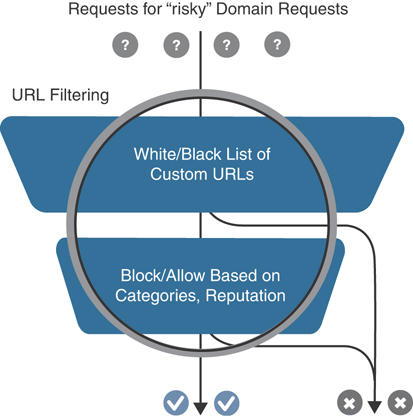
Figure 10-22 URL Filtering Process
Note
To support URL Filtering functionality, an ISR must be configured with a minimum of 8GB of DRAM and 8GB of system flash if doing cloud lookup. A minimum of 16GB of DRAM and 16GB of system flash is required if doing on-box database lookup.
Before a URL Filtering policy can be configured, the network operator must upload a security virtual image to vManage under the software repository section (as discussed in the “Intrusion Detection and Prevention” section of this chapter). The security virtual image can be downloaded from the Cisco software portal and is packaged in TAR format. If a security virtual image was previously uploaded for another Cisco SD-WAN security functionality, no additional image is required.
Like all other security features available in Cisco SD-WAN, the first place to start is by navigating to the security section and either building a new security policy (following the simple workflow to build a URL Filtering policy) or directly navigating to the URL Filtering policy subsection under Custom Options. Figure 10-23 highlights the process. No matter how the URL Filtering policy is configured, it must eventually be tied to an overall security policy, which is then attached to the branch WAN Edge router template.
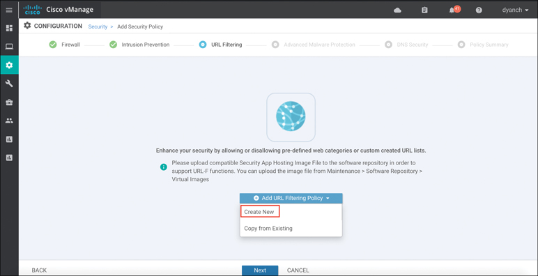
Figure 10-23 URL Filtering Policy Workflow
The following is a summary of steps required to configure a URL Filtering policy in Cisco SD-WAN:
Step 1. Create a new URL Filtering policy. Name the policy.
Step 2. Configure web categories. Specify the blocked or allowed web category list.
Step 3. Configure the web reputation. Specify the web reputation for allowed websites.
Step 4. Configure whitelist URL list (optional). Specify the URLs that should always be allowed.
Step 5. Configure blacklist URL list (optional). Specify the URLs that should always be blocked.
Step 6. Configure block page (optional). Specify the block page content.
Step 7. Configure the alerts and logs (optional). Specify which alerts should be generated.
Step 8. Configure target VPNs. Specify the VPNs to be inspected.
The URL Filtering engine allows for the network operator to select from a list of five reputation levels. The website’s reputation will be considered if it does not match any custom lists and was allowed through the configured web categories. The URL Filtering web reputation engine will allow sites based on a numerical value (between –10 and 10) assigned to the site by Cisco Talos. Sites that either meet the configured reputation level or are of a lower risk level will be allowed. Administrators can approve websites using preconfigured reputation levels (that is, Trustworthy or High Risk). A whitelist and blacklist can also be specified that can leverage regular expression entries for more flexibility. Figure 10-24 depicts the policy behavior as well as the configuration options available.
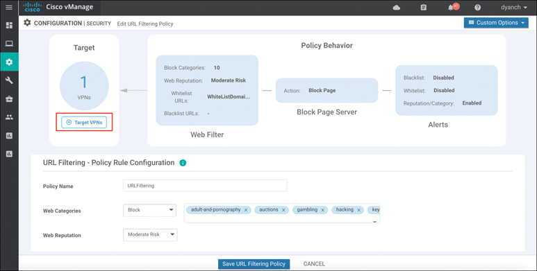
Figure 10-24 URL Filtering Configuration
For blocked websites, the network operator can select between a built-in block page (with customizable content) and a redirect URL. URL Filtering alerts are user definable and can provide insight into blacklist, whitelist, and reputation/category hits.
Once the URL Filtering policy options are configured, a target VPN or VPNs must be defined in order for the engine to know which segments on the branch WAN Edge router need to be inspected by the URL Filtering engine.
Lastly, the security policy containing the URL Filtering policy must be attached to a branch template for deployment.
Note
As a best practice, configure a Security App Hosting template to be referenced under the Container Profile section. The template can retain default settings. If the WAN Edge router is equipped with 16GB flash and 16GB memory, and on-box URL Filtering database is required, select “high” for the Resource Profile option in the template.
Note
If an application service-based security feature has never been enabled on a particular ISR before, a container installation task will automatically begin after the security policy is attached to the branch template. Once this installation is complete, the security policy will be enabled. This task can be monitored for successful completion by navigating to the active task pane at the top right of the Cisco vManage dashboard.
Monitoring of the URL Filtering statistics can be accessed through the main security dashboard or, for more complete details, through the URL Filtering section of the device dashboard. The security dashboard screen can show the top hitting blocked and allowed URL categories by percentage as well as the amount of times the category was hit, as illustrated in Figure 10-25. In addition, this view can provide details around which WAN Edge router on the Cisco SD-WAN is contributing to the category hits.

Figure 10-25 URL Filtering Security Dashboard View
The device dashboard URL Filtering screen, shown in Figure 10-26, presents the same data in a bar graph format with more historical resolution and includes reputation block counts.

Figure 10-26 URL Filtering Device Dashboard View
Only ISR and CSR platforms that support IOS-XE SD-WAN code are capable of running the URL Filtering functionality.
Please refer to the Cisco SD-WAN Security Configuration Guide published on the Cisco documentation site for additional deployment details.
Note
More detailed URL Filtering statistics can be gathered through the Real Time section of the device dashboard or via CLI show command sets.
Advanced Malware Protection and Threat Grid
Advanced Malware Protection (AMP) and Threat Grid are the newest additions to Cisco SD-WAN security. As with URL Filtering, both AMP and Threat Grid leverage the Snort engine and Talos for inspection of file downloads and detection of malware in real time. AMP can block malware trying to enter your network using antivirus detection engines, one-to-one signature matching, machine learning, and fuzzy fingerprinting. Figure 10-27 shows this process at a high level.

Figure 10-27 Advanced Malware Protection Process
Cisco Talos experts analyze millions of malware samples and terabytes of data per day and push that intelligence to AMP. AMP then correlates files, telemetry data, and file behavior against this context-rich knowledge base to proactively defend against known and engaging threats. If the AMP cloud is unable to determine if the file being inspected is good or bad, advanced sandboxing through Threat Grid can be leveraged and retrospective analysis can be performed. Threat Grid combines advanced sandboxing with threat intelligence into one unified solution to protect organizations from malware. With a robust, context-rich malware knowledge base, the network operator can understand what malware is doing (or attempting to do), how large a threat it poses, and how to defend against it.
When a file is downloaded, the Snort file preprocessor on the WAN Edge router identifies the file download, computes the SHA256 hash for the file, and looks it up in the local cache to learn if it is a known good or bad hash. If no match is found in the local database, the hash is 374sent to the AMP cloud for identification. The AMP cloud can then respond with one of three responses:
Clean: If clean, the file download is allowed to complete.
Malicious: If malicious, the file download is interrupted and stopped.
Unknown: If unknown (provided that Threat Grid is enabled) and active content is found, the WAN Edge router sends the file to Threat Grid for sandboxing. The WAN Edge router queries Threat Grid for a period of time and then queries AMP for retrospection. Threat Grid then updates the new status of the hash in the AMP cloud once it is known.
Note
As of the publication of this book, the current SD-WAN code supports a maximum exportable file size of 10MB.
The following is a summary of steps required to configure an Advanced Malware Protection and Threat Grid policy in Cisco SD-WAN:
Step 1. Create a new AMP policy. Name the policy.
Step 2. Configure AMP cloud region. Specify the region to use for AMP cloud: North America (NAM), Europe (EU), or Asia Pacific (APJC).
Step 3. Configure the AMP alerts log level. Specify which alerts level should be considered.
Step 4. Enable Threat Grid file analysis (optional). Enable Threat Grid file analysis, if applicable.
Step 5. Configure Threat Grid API key. Specify the Threat Grid API key.
Step 6. Configure file types. Specify, from a list, the file types to be inspected.
Step 7. Configure the Threat Grid alerts log level. Specify which alerts level should be considered.
Step 8. Configure target VPNs. Specify the VPNs to be inspected.
Note
To support AMP functionality, an ISR must be configured with a minimum of 8GB of DRAM and 8GB of system flash.
Before an AMP policy can be configured, the network operator must upload a security virtual image to vManage under the software repository section, as depicted in the “Intrusion Detection and Prevention” section of this chapter. The security virtual image can be downloaded from the Cisco software portal and is packaged in TAR format.
Like all other security features available in Cisco SD-WAN, the first place to start is by navigating to the security section and either building a new security policy (following the simple workflow to build an AMP policy) or directly navigating to the AMP policy subsection under Custom Options, as shown in Figure 10-28. No matter how the AMP policy is configured, it must eventually be tied to an overall security policy, which is then attached to the branch WAN Edge router template.

Figure 10-28 AMP Policy Workflow
The AMP engine allows for the network operator to configure the AMP cloud region in order to have the most optimal experience, based on the location of the branch site. Cisco supports AMP clouds in North America, Europe, and Asia. Three levels of alerts logging can also be configured: Info, Warning, and Critical. If the SD-WAN license acquired provides entitlement to Thread Grid, the API key must be configured before it can be used. Once file analysis is enabled, the Threat Grid cloud region must also be selected.
Figure 10-29 depicts the workflow in vManage. Once the AMP and Threat Grid policy options are configured, a target VPN or VPNs must be defined in order for the engine to know which segments on the branch WAN Edge router need to be inspected by the AMP engine.
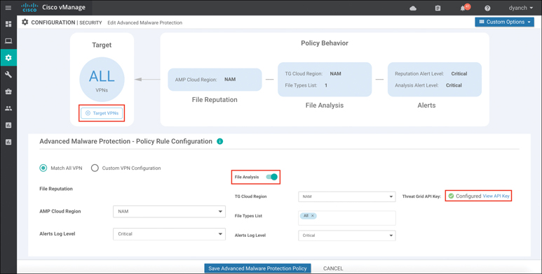
Figure 10-29 AMP Policy Configuration
Lastly, the security policy containing the AMP policy must be attached to a branch template for deployment.
Note
As a best practice, configure a Security App Hosting template to be referenced under the Container Profile section. The template can retain the default settings. If the WAN Edge router is equipped with 16GB flash and 16GB memory and Threat Grid is being leveraged in the policy, select “high” for the Resource Profile option in the template.
Note
If an application service-based security feature has never been enabled on a particular ISR before, a container installation task will automatically begin after the security policy is attached to the branch template. Once this installation is complete, the security policy will be enabled. This task can be monitored for successful completion by navigating to the active task pane at the top right of the Cisco vManage dashboard.
Monitoring of the AMP statistics can be accessed through the main security dashboard or, for more complete details, through the AMP section of the device dashboard. The security dashboard screen, shown in Figure 10-30, can show historical information on the number of malicious files being detected via AMP and the number of files being exported to Threat Grid for analysis. This view can also provide details around which WAN Edge router is contributing to the most AMP cloud reputation hits.

Figure 10-30 AMP Security Dashboard View
The AMP device dashboard provides a historical view of the number of file hashes the AMP cloud has registered as well as the AMP cloud response of those file hashes. In addition, this view details the filename, the hash value, the file type, the disposition, the timestamp, the VPN, and the action the WAN Edge router took for the file. Figure 10-31 portrays the AMP device dashboard.
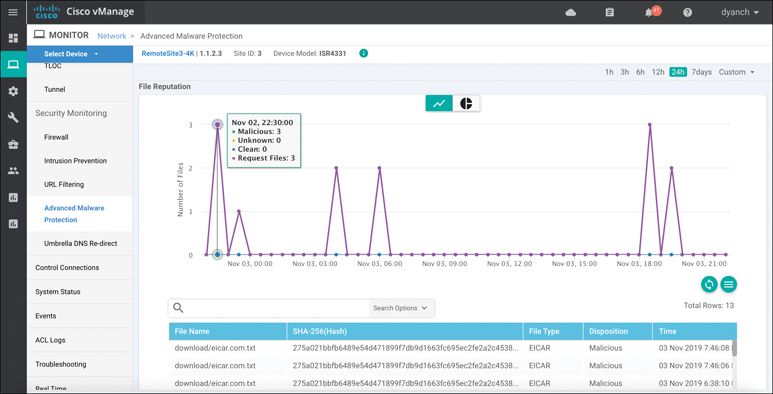
Figure 10-31 AMP Filtering Device Dashboard View
Only ISR and CSR platforms that support IOS-XE SD-WAN code are capable of running the Advanced Malware Protection and Threat Grid functionality.
Please refer to the Cisco SD-WAN Security Configuration Guide, published on the Cisco documentation site, for additional deployment details.
Note
More detailed AMP statistics can be gathered through the Real Time section of the device dashboard or via CLI show command sets.
DNS Web Layer Security
Cisco SD-WAN security leverages the Cisco Umbrella cloud in order to bring a comprehensive, VPN-aware, suite of web security tools and enhanced cloud application visibility to the branch. DNS Web Layer security integration prevents enterprise branch users and guests from accessing inappropriate content or malicious sites that might contain malware, phishing attacks, and other security risks. Once registered with Umbrella cloud, the WAN Edge router intercepts DNS requests from the LAN and redirects them to Umbrella resolvers. If the requested page is a known malicious site or is not allowed (based on the policies configured in Umbrella portal), the DNS response will contain the IP address for an Umbrella-hosted block page. The DNS response will contain the IP address of the destination website if the site is considered to have good reputation, is not malicious, and is allowed by the policy configured on the Umbrella portal. If Umbrella is not completely certain that the page being requested is safe, Intelligent Proxy can be enabled so that the Umbrella cloud acts as a man-in-the-middle. In this way, Umbrella can inspect the page data as it loads to avoid compromising the security of the end user.
DNS Web Layer security supports DNSCrypt, EDNS, and TLS decryption as well. In the same way that SSL turns HTTP web traffic into HTTPS encrypted web traffic, DNSCrypt turns regular DNS traffic into encrypted DNS traffic that is secure from eavesdropping and man-in-the-middle attacks. It does not require any changes to domain names or how they work; it simply provides a method for securely encrypting communication between the end user and the DNS servers in Umbrella cloud. Extension mechanisms for DNS (EDNS) is a specification for expanding the size of several parameters of the DNS protocol, so as to carry metadata (such as VPN ID) for additional context that can be leveraged in an Umbrella cloud policy.
In some scenarios, it may be important not to intercept DNS requests for internal resources and pass them on to an internal or alternate DNS resolver. To meet this requirement, the WAN Edge router can leverage local domain bypass functionality, where a list of internal domains is defined and referenced during the DNS request interception process. Any domain defined in the list is ignored, and no interception or redirection occurs. Figure 10-32 highlights the DNS Web Layer security process from a high level.
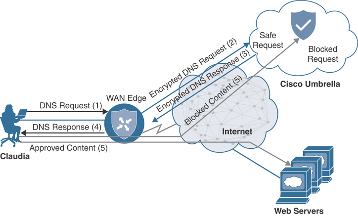
Figure 10-32 DNS Web Layer Security Process
The following is a summary of steps required to configure DNS Web Layer security with Cisco Umbrella:
Step 1. Create a new DNS Security policy. Name the policy.
Step 2. Generate and register Umbrella API token. In the Umbrella cloud portal, generate an API token and configure vManage with the token so as to register with Umbrella cloud.
Step 3. Configure local domain bypass list (optional). Define the list of local domains that should bypass inspection.
Step 4. Configure DNS server IP. Specify the DNS server to use for redirection: Umbrella default or a custom DNS.
Step 5. Configure DNSCrypt. Enable or disable DNSCrypt.
Step 6. Configure target VPNs. Specify the VPNs to be inspected.
Note
DNS Web Layer security enforcement through Umbrella cloud requires a specific SD-WAN license tier. Cloud application visibility through Umbrella cloud portal is available in all SD-WAN license tiers.
Before a DNS security policy can be configured, the network operator must register vManage with the Umbrella cloud portal through the generation and application of an Umbrella API token. This token facilitates the automatic registration of the WAN Edge router with Umbrella cloud so that interception and redirection of DNS requests are authorized and successful. Refer to the Umbrella cloud portal documentation in order to learn how to generate an Umbrella API token. Configure the API token in vManage under the Custom Options, Umbrella API Token menu of the security policy.
Like all other security features available in Cisco SD-WAN, the first place to start is by navigating to the security section and either building a new security policy (following the simple workflow to build a DNS security policy) or directly navigating to the DNS security policy subsection, under Custom Options, as shown in Figure 10-33. No matter how the DNS security policy is configured, it must eventually be tied to an overall security policy, which is then attached to the branch WAN Edge router template.

Figure 10-33 DNS Security Policy Workflow
The DNS security policy allows for the network operator to verify that the Umbrella registration status is configured. If the registration status is not configured, tooltips are provided to direct the network operator on how to configure vManage with the API token. A local domain bypass list can also be configured and can support “*” for wildcard matching, but an entry cannot be more than 240 characters in length. The default DNS server IP of Umbrella can be used in the policy or, alternatively, a custom DNS server IP can be set. DNSCrypt can be enabled or disabled in the DNS security policy as well. Figure 10-34 illustrates these available options and settings.
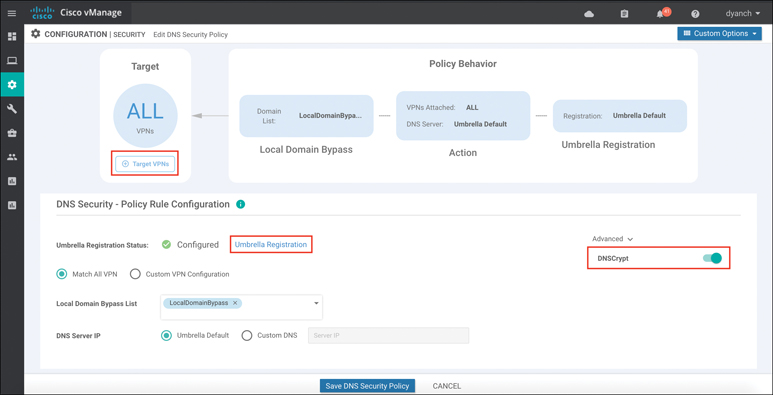
Figure 10-34 DNS Security Configuration
Once the DNS security policy options are configured, a target VPN or VPNs must be defined in order for the engine to know which segments on the branch WAN Edge router are candidates for DNS interception and redirection.
Lastly, the security policy containing the DNS security policy must be attached to a device template for deployment.
vManage provides only basic monitoring of DNS security interception and redirection, as shown in Figure 10-35. Detailed monitoring around policy enforcement, cloud app visibility, and other Umbrella cloud–specific information should be consumed through the Umbrella cloud portal itself. The Umbrella DNS Re-direct section of the vManage device dashboard provides a historical overview of DNS requests that were redirected to Umbrella, DNS requests that were bypassed using Local Domain Bypass, timestamps, a count of Umbrella registered VPNs, and the status of DNSCrypt.
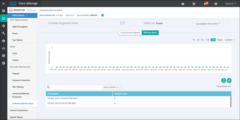
Figure 10-35 DNS Security Device Dashboard View
Note
As of the publication of this book, only IOS-XE SD-WAN supports DNS Web Layer security with Umbrella configuration through security policy. Viptela OS supports interception and redirection, but only through the use of a data policy, which is beyond the scope of this chapter.
All ISR, ASR, and CSR platforms that support IOS-XE SD-WAN code are capable of running the DNS Web Layer security functionality.
Please refer to the Cisco SD-WAN Security Configuration Guide published on the Cisco documentation site for additional deployment details.
Cloud Security
While this chapter focuses mainly on Cisco SD-WAN integrated security, it is important to note that other security models, such as cloud-delivered firewalls, do exist and are valid architectures to bring security to the branch in a Cisco SD-WAN environment. While integrated security provides a convenient and efficient way to consume and manage security at the branch, it can also place a compute burden on the WAN Edge router—effectively lowering its forwarding performance. However, as long as the proper WAN Edge router is selected, based on the required bandwidth for the branch, this is usually not a problem.
Cloud-delivered firewalls provide a means to offload this compute burden onto the provider’s cloud environment, freeing up resources on the WAN Edge router to forward traffic unencumbered. Cloud-delivered firewalls, connected via IPsec or GRE tunnels, are terminated either directly on a WAN Edge router’s DIA circuit or at a hub site where Internet traffic is backhauled to. Figure 10-36 illustrates some of the common cloud security connectivity options.
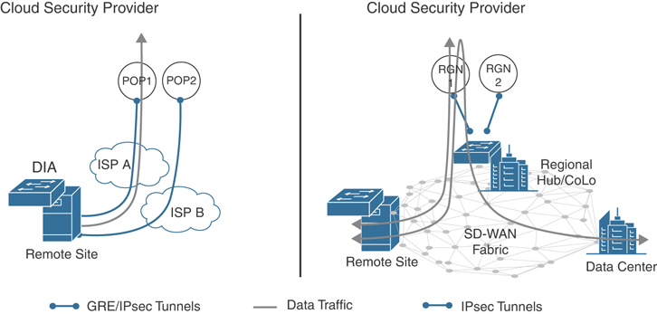
Figure 10-36 Cloud Security Connectivity
Because Cisco SD-WAN supports the configuration and connectivity of standards-based IPsec and GRE tunnels, virtually any cloud-delivered firewall solution can be seamlessly integrated into a WAN Edge router. Simply create a standards-based IPsec or GRE tunnel feature template, fill out the necessary parameters to establish the tunnel, and attach it to a device template. Figure 10-37 shows this configuration pane.
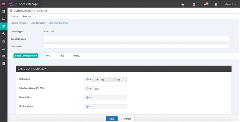
Figure 10-37 Standards-Based IPsec Tunnel Configuration
Note
As of the publication of this book, IOS-XE SD-WAN only supports standards-based IPsec configuration on a service-side VPN. Viptela OS supports both standards-based IPsec and GRE configurations on either the service- or transport-side VPN.
Historical monitoring of the IPsec or GRE tunnel’s utilization, errors, drops, and so on can be found in the device dashboard under the interface section. Figure 10-38 rebreak: show-cases this monitoring as well as the received and transmitted data rates for both IPv4 and IPv6.
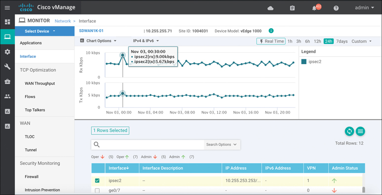
Figure 10-38 IPsec Tunnel Monitoring
More detailed information about the IPsec or GRE tunnel can be gleaned through the Real Time section of the device dashboard, as shown in Figure 10-39. There are multiple device options available to choose from, such as IPsec IKE Inbound Connections and IPsec Outbound Connections.
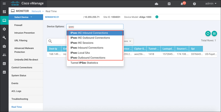
Figure 10-39 Real-Time Tunnel Information
Please refer to the Cisco SD-WAN configuration guides, published on the Cisco documentation site, for additional deployment details.
Note
More detailed standards-based IPsec and GRE statistics can be gathered through the Real Time section of the device dashboard or via CLI show command sets.
vManage Authentication and Authorization
The final component of Cisco SD-WAN security is the hardening of the SD-WAN network management system called vManage. vManage plays a critical role in the overall security of the enterprise. For this reason, it supports a multitude of authentication and authorization methods and functionalities.
Local Authentication with Role-Based Access Control (RBAC)
Users can be authenticated into vManage through a built-in local database that can be found in the Administration section. These users can then be tied to a user group, providing customized access to the solution. There are three predefined user groups: netadmin, operator, and basic. The netadmin user group provides unfettered read and write access to the entirety of vManage. The operator user group provides read-only access to vManage. The basic user group provides read-only access to the interface and system sections of vManage. Custom user groups can also be created, and a combination of read and write access to all components of vManage can be configured.
The following is a summary of steps required to configure a new local database user:
Step 1. Add user. Within the Administration Manage Users section, click Add User under the Users tab.
Step 2. Configure full name. Specify the user’s full name.
Step 3. Configure username. Specify the user’s desired username.
Step 4. Configure password. Specify and confirm the user’s password, which can later be changed at first login, if necessary.
Step 5. Select user group. Select from one of the three predefined user groups or a custom user group.
Figure 10-40 illustrates the process for adding users and groups.
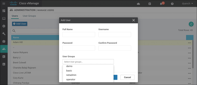
Figure 10-40 Add Users
The following is a summary of steps required to configure a custom user group:
Step 1. Add user group. Within the Administration Manage Users section, click Add User Group under the User Groups tab.
Step 2. Configure user group name. Specify the user group name.
Step 3. Select read and write access. Select the desired read and write access levels.
When you’re creating a user group, read and write options are available for various features. Figure 10-41 showcases the user group configuration pane in vManage.
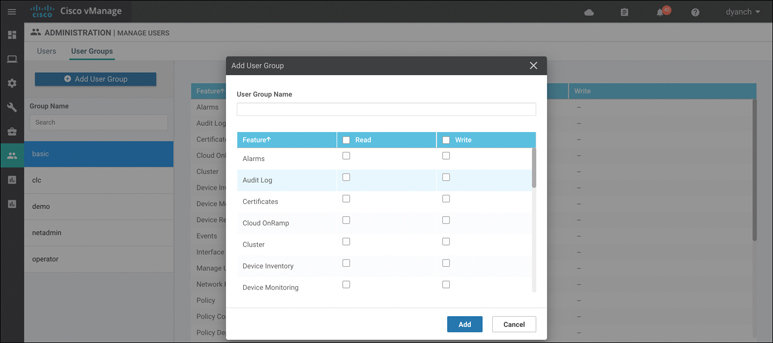
Figure 10-41 Add User Groups
RBAC can also be made to be VPN aware. That is to say, a user can be tied to a specific user group that is assigned to an RBAC group that only provides visibility into a single VPN or a subset of VPNs.
The following is a summary of steps required to configure RBAC by VPN:
Step 1. Configure VPN segments. Within the Administration VPN Segments section, enter a segment name and VPN number. Figure 10-42 illustrates the process to add a VPN number to a VPN segment. This is a way for vManage to tie a VPN number to a name so that it can be referenced later on in a VPN group.
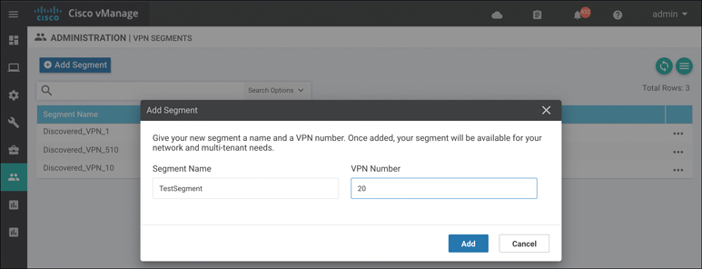
Figure 10-42 Add VPN Segment
Step 2. Configure a VPN group. Within the Administration VPN Group section, enter a VPN group name and description, create the RBAC user group, and assign a segment or multiple segments to the VPN group.
A VPN group is a way for vManage to tie a single or multiple segments to a group that can then be attached to a custom RBAC user group. This RBAC user group will 387appear in the user group section of vManage and can then be tied to the user itself. Figure 10-43 illustrates the process to create a VPN group.

Figure 10-43 Add VPN Group
Step 3. Assign the user to the user group. Select the newly created RBAC user group.
Configure the user to be in the newly created RBAC user group so that, when the user logs in, only the visibility information from the VPNs assigned to the VPN group is consumable. Figure 10-44 shows how to assign a user to a user group.
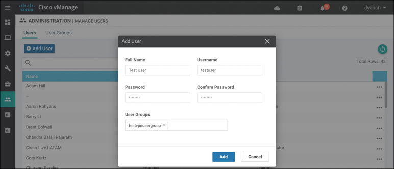
Figure 10-44 Assign RBAC User Group
When a user who is assigned to a user group that is attached to a VPN group logs in, only relevant information to the VPNs allocated in the VPN group will be visible. This includes Device Health, Site Health, WAN Edge Health, and Top 388Applications. This can be seen in Figure 10-45, as it showcases what can be seen in the TestVPNGroup.

Figure 10-45 RBAC by VPN Visibility
Remote Authentication with Role-Based Access Control (RBAC)
vManage also supports remote authentication with role-based access control through the use of a RADIUS/TACACS or Single Sign-On (SSO) authentication server. Figure 10-46 depicts the RADIUS and TACACS configuration pane within vManage. To authenticate via RADIUS/TACACS, simply configure a AAA vManage feature template or manually configure the RADIUS/TACACS server information via vManage CLI. User groups can still be leveraged with remote authentication as long as the authentication server can pass the group name as a parameter to vManage.
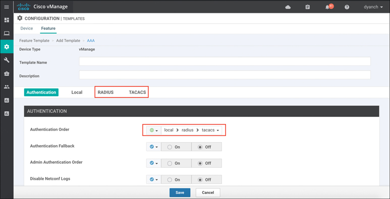
Figure 10-46 RADIUS/TACACS Configuration
To authenticate via SSO, upload a SAML 2.0–compliant metadata file to vManage by navigating to Identity Provider Settings under the vManage settings section. Figure 10-47 highlights how to enable the Identity Provider.
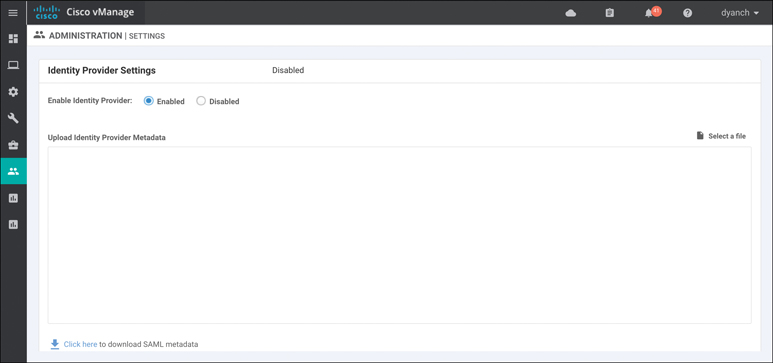
Figure 10-47 SSO Configuration
Please refer to Cisco SD-WAN configuration guides, published on the Cisco documentation site, for additional deployment details.
Summary
This chapter covered all aspects of Cisco SD-WAN security, including integrated functionality, such as Application-Aware Enterprise Firewall, IDS/IPS, URL Filtering, AMP, DNS Web layer security, cloud-delivered firewall connectivity, and vManage authentication and authorization. Cisco’s goal with SD-WAN security is to ensure that no matter what your requirements may be at the branch, a viable option exists to ensure that the appropriate security posture can be attained, managed efficiently, and accessed securely.
Review All Key Topics
Review the most important topics in the chapter, noted with the Key Topic icon in the outer margin of the page. Table 10-3 lists these key topics and the page numbers on which each is found.
Table 10-3 Key Topics
Key Topic Element |
Description |
Page |
|---|---|---|
Section |
Application-Aware Enterprise Firewall |
352 |
Security Policy Application |
358 |
|
Section |
Intrusion Detection and Prevention |
360 |
Section |
URL Filtering |
367 |
Section |
Advanced Malware Protection and Threat Grid |
372 |
Section |
DNS Web Layer Security |
377 |
Define Key Terms
Define the following key terms from this chapter and check your answers in the glossary:
Chapter Review Questions
1. Cisco SD-WAN Application-Aware Enterprise Firewall is not VPN aware.
True
False
2. What are the three actions that can be set in a firewall policy?
Pass
Inspect
Redirect
Export
Drop
3. Logging is not available for Application-Aware Enterprise Firewall policies.
True
False
4. What signature sets are available for selection in an IDS/IPS policy? (Choose three.)
Strict
Balanced
Relaxed
Connectivity
Security
5. Which two Snort engine modes are supported during an engine failure or engine reboot?
Fail-block
Fail-close
Fail-pass
Fail-wide
Fail-open
6. Before an IDS/IPS policy can be configured, the network operator must upload a security virtual image to vManage under the software repository section.
True
False
7. URL Filtering requires a minimum of 4GB DRAM and 4GB flash to be deployed.
True
False
8. What URL Filtering feature can be leveraged to explicitly block certain websites?
Categories
Reputation
URL blacklist
URL whitelist
9. URL Filtering visibility includes which of the following information? (Choose two.)
URLs accessed
Session count
Website reputation
Blocked and allowed categories by percentage
10. The maximum exportable file size for file analysis is 1000 MB.
True
False
11. To configure file analysis for Advanced Malware Protection, which tasks are valid? (Choose three.)
Configure Threat Grid API key.
Configure file types list.
Enable file analysis.
Enable HTTPS inbound to the WAN Edge router.
Configure a security rule for Threat Grid.
12. AMP visibility has the ability to display the malware filename.
True
False
13. How is the Cisco Umbrella API token generated?
Automatically during vManage bootup
Manually in vManage Umbrella settings
By the Cisco SE and provided to the customer by email
In the Cisco Umbrella portal
14. If a customer wants the DNS Web layer security redirection process to ignore a specific set of domains, what feature can be leveraged?
Corporate domain bypass
Domain filtering
Local domain bypass
Domain rules
15. Which two privilege types can be assigned to a user group in vManage?
Read
Erase
Reboot
Administer
Write
16. RBAC by VPN allows some users to configure some VPN features but not others.
True
False
17. Which three remote authentication types are supported by vManage?
Single Sign-On (SSO)
RADIUS
Local
TACACS