Chapter 1. Gateways and Gatekeepers
This book will help you understand the roles of IP voice gateways and gatekeepers and how to integrate them into your voice network.
Gateways can be configured with many different features and functions and can become quite complex. It is important for network engineers to understand gateway functions, be able to choose when to use which, and be able to configure their gateways. Engineers need a thorough understanding of gatekeeper function and configuration to ensure proper call flow. In addition, they must address issues of security and redundancy.
This chapter provides an overview of the basic building blocks of a Voice over IP (VoIP) network. It includes information on the following:
• Voice gateways, H.323 gatekeepers, and IP-to-IP gateways
• IP voice signaling and media protocols
• Call control devices
It also includes an overview of the network used in case studies throughout the book.
The Role of Voice Gateways
The basic function of a gateway is to translate between different types of networks. In the data environment, a gateway might translate between a Frame Relay network and an Ethernet network, for example. In a VoIP environment, voice gateways are the interface between a VoIP network and the public switched telephone network (PSTN), a private branch exchange (PBX), or analog devices such as fax machines. In its simplest form, a voice gateway has an IP interface and a legacy telephone interface, and it handles the many tasks involved in translating between transmission formats and protocols. At least one gateway is an essential part of any IP telephony network that interacts with the PSTN or with analog devices. In addition, when gateways are properly configured, many can take over for a Cisco CallManager when it is unreachable.
Figure 1-1 shows a simple VoIP network with a voice gateway connected to both the VoIP network and the PSTN.
Figure 1-1. Voice Gateway Example
The gateway allows communication between the two networks by performing tasks such as these:
• Interfacing with the IP network and the PSTN or PBX.
• Supporting IP call control protocols, in addition to time-division multiplexing (TDM) call control protocols.
• Performing call setup and teardown for calls between the VoIP and PSTN networks by terminating and reoriginating the call media and signaling.
• Providing supplementary services, such as call hold and transfer.
• Relaying dual tone multifrequency (DTMF) tones.
• Supporting analog fax and modems over the IP network.
• In a Cisco CallManager network, a gateway also needs to do the following:
—Support CallManager redundancy by rehoming to alternate CallManagers.
—Support call survivability when no CallManager is available.
Gateways communicate with other gateways, gatekeepers, their endpoints, or their call control agents, such as Cisco CallManager or a PBX. The following are the protocols that Cisco gateways use for voice signaling and media:
• Media Gateway Control Protocol (MGCP)
• H.323
• Session Initiation Protocol (SIP)
• Skinny Client Control Protocol (SCCP)
• Real-Time Transport Protocol (RTP)
This chapter introduces these protocols. MGCP, H.323, and SIP are described in depth in other chapters of this book.
Types of Voice Gateways
This book deals primarily with using Cisco routers as voice gateways, but an assortment of different types and models of Cisco voice gateways is available. Gateways contain analog or digital telephony ports, in addition to IP interfaces. Analog options include Foreign Exchange Office (FXO) ports, Foreign Exchange Station (FXS) ports, and Ear and Mouth (E&M) ports. Digital options include T1/E1 PRI ports, ISDN BRI ports, and T1 channel associated signaling (CAS) ports. You can divide Cisco gateways into several categories, each with its own capabilities. For more information on the current models, visit www.Cisco.com.
Routers
You can use many Cisco routers, such as 1700, 2600, 2800, 3600, 3700, 3800, 7200, and 7500 models, as voice gateways. Voice gateway routers can contain analog ports such as FXO and FXS, and digital ports such as E1 and T1. Most can use the MGCP, SCCP, SIP, and H.323 protocols. The remainder of this book focuses mainly on router-based voice gateways.
Standalone Voice Gateways
Unlike routers, standalone voice gateways are used only as voice gateways. They come in two types: digital and analog.
Digital trunk gateways, such as the AS5000 series interface, connect an IP telephony network and the PSTN or a PBX via their trunk ports.
Analog trunk gateways, such as AT-2 or AT-4, connect to the PSTN or a PBX via analog trunks. Analog station gateways, such as an ATA186, VG224, or VG248, connect to analog devices such as telephones, fax machines, or voice-mail systems. The signaling protocols that are available vary by gateway model. The ATA186, an analog-to-IP adapter, can support two analog devices each with its own telephone number. It has one Ethernet port that connects to the VoIP network, and two voice ports for connecting analog devices. It can be controlled by Cisco CallManager and CallManager Express, and it supports SIP and SCCP protocols. However, CallManager 5.0 does not have native SIP support for the ATA186.
VG224 and VG248 are Cisco voice gateways with 24 and 48 analog FXS ports, respectively. These are line-side gateways—they do not interface with the PSTN, but with end-user analog devices. Both models allow a CallManager, CallManager Express (CME), or an SRST router multiple to control analog ports. They connect to a LAN via an Ethernet port, and they communicate with CallManager or CME using the SCCP telephony control (STC) application. The VG224 can also act as an MGCP, H.323, or SIP gateway.
The analog telephones, faxes, or modems that are attached to the gateway appear as individual endpoints to the CallManager. You must configure the gateway on the CallManager, and you must configure each port on CallManager with a directory number and any call features it needs. In CME, you must set up an e-phone for each port in use.
The VG248 gateway uses only SCCP. The VG224 gateway can use SCCP, H.323, MGCP, and SIP. CME interaction is supported only with the VG224 gateway, not VG248. The VG224 gateway is Cisco-IOS based, whereas configuration of the VG248 gateway is menu driven.
Switch Modules
Modules containing analog and digital ports are available for Cisco 6500 switches, allowing them to act as voice gateways. For example, the Communication Media Module (which you can also use in the 7600 series router) can contain a combination of T1, E1, and FXS ports. It uses MGCP, H.323, and SIP protocols, and it can provide Survivable Remote Site Telephony (SRST) functionality. The Voice T1/E1 and Services Module, or 6608 blade, can contain T1 or E1 interfaces, and it can perform as an MGCP gateway.
The Role of Voice Gatekeepers
Gatekeepers help VoIP networks scale to large sizes. Companies that have geographically dispersed voice networks, or networks that have become so large that they are unwieldy, might opt to segment their network. In a CallManager network, you can create multiple clusters. In that case, you would need to configure a full mesh of connections over the IP WAN to link all the segments or clusters. You would need to configure dial information for every remote location on every gateway and CallManager cluster. A better alternative is to use gatekeepers. In a network that has gatekeepers, trunks are needed only to the gatekeeper, and the gatekeeper maintains remote endpoint information.
When you use gatekeepers, gateways and CallManagers register with their gatekeeper. Gatekeepers divide the network into “zones,” or groups of devices that register with a particular gatekeeper. When an H.323 gateway receives a call that is destined to a remote phone, it queries the gatekeeper for the location of the endpoint. If the call is destined for a different zone, you can configure the gatekeeper to allow it only if sufficient bandwidth is available. In more complex networks, you can use a Directory gatekeeper to maintain information about all the zones. You can configure Cisco routers with the appropriate Cisco IOS as H.323 gatekeepers.
Figure 1-2 shows an example of a company that has three CallManager clusters and a gatekeeper. Each cluster has an intercluster trunk over the IP WAN to the gatekeeper. Each cluster is its own zone.
Figure 1-2. H.323 Gatekeeper Example

Gatekeeper functionality is part of the H.323 standard. A voice gatekeeper provides the following services:
• Address resolution—A gatekeeper resolves E.164 telephone numbers and H.323 IDs to endpoint IP addresses.
• Call admission control—A gatekeeper permits or denies a call between clusters.
• Bandwidth control—A gatekeeper can refuse to admit calls that exceed the allocated bandwidth.
• Zone management—A gatekeeper can register and manage endpoints within its zone.
• Optional Security—A gatekeeper can authenticate and authorize calls on an endpoint-by-endpoint basis.
• Optional call management—A gatekeeper can maintain information about the endpoint call state.
• Optional routing of call control signaling—A gatekeeper can reroute signaling to allow endpoints to communicate directly.
The Role of IP-to-IP Gateways
A voice gateway joins a VoIP network and the PSTN. A gatekeeper joins separate segments of the same VoIP network. An IP-to-IP gateway (IPIPGW), often called a Session Border Controller, joins independent VoIP or Video over IP networks. It acts as a border device, allowing users in different administrative domains to exchange voice and video using IP, rather than through the PSTN. The call media can either flow through the gateway, or directly between endpoints.
For example, an Internet Telephony Service Provider (ITSP) can use IPIPGWs to route IP voice traffic through another ITSP network. An IPIPGW can provide billing information to the ITSP. IPIPGWs can allow an ITSP to offer its customers end-to-end VoIP service between each other, or between remote offices of the same company. This would allow the exchange of IP calls between CallManager, H.323, and SIP networks.
Figure 1-3 shows an example of two companies that frequently conduct videoconferences between them. They use an IPIPGW to hide the details of each network, while still allowing communication. The H.323 video systems at each location communicate with the IPIPGW, rather than with each other directly. To each network, it looks as if the call signaling originates at the IPIPGW. The IPIPGW acts as a Session Border Controller (SBC) between the two islands, controlling video conferencing between them.
Figure 1-3. IP-to-IP Gateway Example

In Figure 1-3, a Voice Infrastructure and Applications (VIA) zone is used, along with a gatekeeper. This zone acts as a transit zone between the two networks. The gatekeeper is especially configured to route calls appropriately to the IPIPGW.
You can install the IP-to-IP gateway Cisco IOS feature set on many Cisco multiservice routers. The following are some features of an IP-to-IP gateway:
• Interconnecting segments of the same or different VoIP networks using different signaling types, such as H.323 and SIP
• Interconnecting segments of the same or different VoIP networks using different media types
• Billing abilities
• Coder/decoder (codec) control
• Call admission control
• Security
Introduction to Voice Protocols
VoIP has several call signaling and control protocols available for use. The protocol that you should use depends on the type of gateway, endpoint host, and call agent, and the capabilities you need in the network. Multiple protocols might be used in different portions of the network. After you set up the call, you transmit IP voice and video traffic using a different protocol, RTP. This section gives an overview of IP signaling and media protocols used in a VoIP network.
Media Gateway Control Protocol
MGCP is a client-server call control protocol, built on centralized control architecture. All the dial plan information resides on a separate call agent. The call agent, which controls the ports on the gateway, performs call control. The gateway does media translation between the PSTN and the VoIP networks for external calls. In a Cisco-based network, CallManagers function as the call agents. This book deals with CallManager-controlled MGCP gateways only; other call agents are beyond the scope of this book.
MGCP is an Internet Engineering Task Force (IETF) standard that is defined in several RFCs, including 2705 and 3435. Its capabilities can be extended by the use of “packages” that include, for example, the handling of DTMF tones, secure RTP, call hold, and call transfer.
An MGCP gateway is relatively easy to configure. Because the call agent has all the call-routing intelligence, you do not need to configure the gateway with all the dial peers it would otherwise need. A downside, however, is that a call agent must always be available. Cisco MGCP gateways can use SRST and MGCP fallback to allow the H.323 protocol to take over and provide local call routing in the absence of a CallManager. In that case, you must configure dial peers on the gateway for use by H.323.
H.323
H.323 is an International Telecommunications Union Telecommunication Standardization Sector (ITU-T) standard protocol. It has its roots in legacy telecommunications protocols, so it communicates well with hosts on the PSTN. H.323 is actually a suite of protocols that specify the functions involved in sending real-time voice, video, and data over packet-switched networks. Unlike MGCP, an H.323 gateway does not require a call agent; it is built on a distributed architecture model. Gateways can independently locate a remote host and establish a media stream; thus, you must configure them with call routing information.
Although an H.323 gateway does not require a call agent, you can use it in a CallManager network. The CallManager directs calls that are bound for the PSTN to the gateway, which uses plain old telephone service (POTS) dial peers to route them. The gateway has a VoIP dial peer pointing to CallManager for calls that are bound inside the VoIP network. You can configure IP phones to register directly with an H.323 gateway using SRST when their CallManager is unavailable.
The H.323 standard defines four components of an H.323 system: terminals, gateways, gatekeepers, and multipoint control units (MCU).
• Terminals—These are the user endpoints, such as a video conferencing units, that communicate with each other.
• Gateways—Used to communicate with terminals on other networks (primarily across the PSTN).
• Gatekeepers—Translate phone numbers to IP addresses, and control and route calls.
• Multipoint control units (MCU)—Enable multiple parties to join a videoconference.
Session Initiation Protocol
SIP, like MGCP, is an IETF standard, which is defined in a number of RFCs. Its control extends to audio, video, data, and instant messaging communications, allowing them to interoperate. SIP uses a distributed architecture based somewhat on the Internet model, using clear text request and response messages and URLs for host addressing. The protocol addresses only session initiation and teardown. It relies on other protocols, such as HTTP for message format, Session Description Protocol (SDP) for negotiating capabilities, and the Domain Name System (DNS) for locating servers by name. The driving force behind SIP is enabling next-generation multimedia networks that use the Internet and Internet applications.
SIP uses several functional components in its call setup and teardown. Because these are logical functions, one device could serve several functions. SIP entities can act as a client or server, and some can act as both. Clients initiate requests for a service or information, and servers respond. One call might involve several requests and responses from several devices. Some SIP functions are as follows:
• User agent—The SIP endpoint, such as a SIP phone, which generates requests when it places a call and answers requests when it receives a call.
• Proxy server—The server that handles requests to and from a user agent, either responding to them or forwarding them as appropriate.
• Redirect server—The server that maintains routing information for remote locations and responds to requests from proxy servers for the location of remote servers.
• Registrar server—The server that keeps a database of user agents in its domain and responds to requests for this information.
• Presence server—The server that supports SIP for Instant Messaging and Presence Leveraging Extensions (SIMPLE) applications. It collects and communicates user and device status, communications capabilities, and other attributes.
SIP is a developing standard; therefore, interoperability between vendors and with other VoIP protocols can be a challenge. Much work is being done in this area, as SIP becomes more widely adopted.
Skinny Client Control Protocol
Cisco IP phones use the Cisco proprietary Skinny Client Control Protocol (SCCP), or “Skinny,” to communicate with their call agent. As the “skinny” portion of the name implies, SCCP is a lightweight protocol that is built on a client-server model. Call control messages are sent over TCP. End stations use SCCP to register with their call agent, and then to send and receive call setup and teardown instructions.
Routers in SRST mode can use SCCP to communicate with the Cisco IP phones they control. Some analog gateway devices, such as a VG224 and Analog Telephone Adapter (ATA), can also use Skinny to communicate with a call agent.
Real-Time Transport Protocol
MGCP, H.323, SIP, and SCCP are protocols that handle call signaling and control. RTP is an IETF standard protocol that uses User Datagram Protocol (UDP) to carry voice and video media after the call is set up. Its header includes a sequence number so that the receiver knows if packets are arriving in the correct order, and a timestamp field to calculate jitter. The RTP, UDP, and IP headers together equal 40 bytes, which can be much larger than the voice data carried in the packet. RTP header compression (cRTP) compresses these three headers as small as 2 to 4 bytes to save bandwidth on low-speed links. The Real-Time Transport Control Protocol (RTCP) allows monitoring of the call data, including counts of the number of packets and bytes transmitted. Secure versions of RTP (SRTP) and RTCP (SRTCP) encrypt the media streams between hosts. Chapter 8, “Connecting to an IP WAN,” has more information on using cRTP and SRTP with gateways.
Call Control Agents
You can deploy gateways with many different kinds of call control agents, and they might perform different roles with different ones. The following sections examine some types of call control agents and some gateway considerations for each type.
Cisco CallManager
Cisco CallManager is a call processing application that runs on a server. It is a part of the Cisco Unified Communications solution. You can install CallManager software on multiple clustered servers to achieve high availability and scalability. CallManager can manage both local and remote phones and gateways. For increased scalability, you can deploy multiple clusters and achieve end-to-end IP voice and video communication. CallManagers handle address resolution and call admission control for their registered phones, but they can also interact with H.323 gatekeepers for those functions. Cisco CallManagers can interact with gateways using MGCP, SCCP, SIP, and H.323.
Cisco CallManager Express
CME is an application on a Cisco IOS router that provides standalone call control for small to medium sites. The number of phones supported varies with the type of router, up to a maximum of 240. With CME, the same router can perform typical gateway functions, such as PSTN connectivity, and also call processing functions. Although CME does not provide all the features of a full CallManager installation, it meets the needs of smaller sites. In addition, you can use extensible markup language (XML) applications to provide users with enhanced features. CME can interoperate with gateways using SCCP, H.323, and SIP.
CME can also integrate with a CallManager network. You can use H.323 trunks between CallManager and a CME router to carry calls over an IP WAN. If the site grows, you can expand call capacity by adding the site to a CallManager cluster and using the router solely as a gateway.
SIP Proxy Server
The Cisco SIP proxy server application runs on a server, providing call routing and control services to SIP endpoints, such as phones or PC applications. It combines the functions of a standard SIP proxy server and a SIP registrar. Endpoints register with the proxy server, which builds a database. When the server receives a SIP call setup message, it attempts to resolve the address with its local information, before forwarding a request to remote servers. It can also authenticate and encrypt SIP messages. You can use redundant servers to provide high availability and load balancing.
Cisco Enterprise Gateway
The Enterprise Gateway (EGW) is an application that runs on the same type of server as CallManager. It acts as a transition point for VoIP and legacy TDM networks, providing call control, signaling, and routing for calls between the two networks. It eases the migration to a CallManager VoIP network by allowing legacy PBXs to communicate with CallManager-controlled phones and Unity voice-mail servers. It also facilitates deploying toll bypass with legacy PBXs. When using an EGW, voice-enabled routers connect to the PBX or the PSTN, acting as media gateways. The router backhauls call control information to the EGW and does the actual media conversion between the TDM and packet networks. The EGW uses MGCP to control the media gateway, SIP, to communicate with a Unity server, and H.323 to communicate to devices in the CallManager network.
PBX with Toll Bypass
A call agent does not have to reside on the VOIP network—a PBX can perform that function for a gateway. A company that wants to retain its existing legacy telephone structure can leverage its IP WAN for intrasite calls. You would need to connect a voice gateway to the PBX using a telephony interface, such as an E&M or PRI. You also need to provide access to the WAN. When an analog phone calls another company site, the PBX can route it to the voice gateway rather than across the PSTN. The PBX can also perform call admission control, rerouting calls to the PSTN when the link between it and the gateway is busy. This is called toll bypass. The voice gateway translates between the legacy voice and the IP voice signaling and media.
Deployment Scenarios
Three typical CallManager deployment scenarios exist:
• Multisite with centralized call control
• Multisite with distributed call control
Each scenario has different ways of using gateways and gatekeepers.
Single Site Deployment
In the single site model, a central call agent serves one location, such as a building or campus. In small sites, this might be a Cisco CME. Larger sites might use a CallManager cluster. All telephones calls outside the site are sent through the PSTN. Telephone calls within the site traverse the LAN or perhaps metropolitan-area network (MAN). Figure 1-4 shows a typical single site deployment.
Figure 1-4. Single Site Deployment
The example shows a small CallManager cluster used as the call agent. In this deployment, gatekeepers are not needed. Gateways connect the LAN to the PSTN, and sometimes to a PBX. For added redundancy, two gateway routers are used. The G.711 codec is used, because bandwidth is not an issue. The gateway Digital Signal Processor (DSP) resources provide conferencing and media termination point (MTP) resources. To simplify gateway configuration, MGCP is used as the call control protocol. If some specific H.323 or SIP functionality is needed, you could use those protocols instead.
Multisite with Centralized Call Control
A company uses this type of deployment when it wants to include multiple sites in its VoIP network, but centralize the call agents. Typically, a CallManager cluster is located at the headquarters or data center site, with perhaps redundant servers at a backup site. The IP phones in remote locations register to the centralized CallManagers, in a hub-and-spoke type arrangement. Remote sites are connected in a full mesh across an IP WAN. Both call signaling and IP voice are sent over the WAN. PSTN access is usually still provided locally. Figure 1-5 illustrates this type of scenario.
Figure 1-5. Multisite Deployment with Centralized Call Control
The gateways at each location interface with the PSTN, the LAN, and the IP WAN. They might also interface with a PBX at some sites. They provide backup call processing by using SRST if the CallManagers are not available because of WAN failure. You can use the G.729 codec across the WAN; use quality of service (QoS) for best results. A gatekeeper is not required for call admission control, but you can use it for dial plan resolution if many remote sites exist.
Multisite Deployment with Distributed Call Control
If the number of remotes sites grows unwieldy, or sites are widely distributed, you can use a multisite scenario with distributed call control. Each “site” in this scenario might be one of three types:
• A single location or campus using CallManager, CME, or another IP PBX
• A multisite CallManager cluster with centralized call control
• A site with a legacy PBX and a VoIP gateway
Figure 1-6 shows an example of this type of network.
Figure 1-6. Multisite Deployment with Distributed Call Control
Multiple CallManager clusters are used, and gatekeepers are used for at least call admission control and address resolution. You can add a directory gatekeeper to scale the gatekeeper implementation. If gatekeepers are used, H.323 gateways are used also. Sites are connected across an IP WAN, with PSTN backup in case of WAN failure or insufficient bandwidth. You typically use the G.729 codec across the IP WAN. Use QoS for best results.
Case Study: Introduction
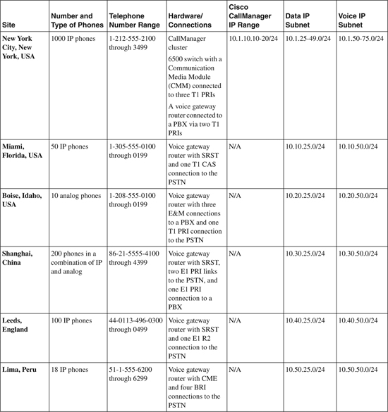
The case studies for this book use a fictional international company with offices in six locations, as shown in Figure 1-7. Each office has a different set of equipment and network connections to demonstrate the various technologies mentioned in this book. Every location communicates with the others over a Multiprotocol Label Switching (MPLS) network that the ISP manages. A centralized CallManager in the New York office controls phones in Miami, Boise, Shanghai, and Leeds. The Lima voice gateway router is running CME for its phones. Boise has analog phones, Shanghai has a combination of IP and analog, and the other sites have IP phones.
Figure 1-7. Complete Case Study Network
Table 1-1 lists each site and the composition of its voice network. It shows the number of IP and analog phones, the phone number range, the type of hardware, and the IP addressing scheme. You might find it helpful to refer back to this table as you read through the remaining case studies in this book.
Table 1-1. Description of Case Study Sites
Chapter Review Questions
1 What are three tasks that a voice gateway performs?
2 What are two benefits of adding an IPIPGW between networks?
3 What are four tasks that an H.323 gatekeeper performs?
4 Which call control protocol is an IETF standard that requires a call agent to function?
5 Which call control protocol is an IETF standard, uses a distributed call-control model, and is able to control multiple types of media connections?
6 Which call control protocol is an ITU-T standard and uses a distributed call-control model?
7 What are three typical CallManager deployment scenarios?