Chapter 4. Session Initiation Protocol
The Session Initiation Protocol (SIP) is an Internet Engineering Task Force (IETF) standard call control protocol, based on research at Columbia University by Henning Schulzrinne and his team. The first SIP RFC, number 2543, was published in 1999. Since then, much work has been done, and numerous RFCs have been published to solidify and extend SIP capabilities.
SIP is designed to provide signaling and session management for voice and multimedia connections over packet-based networks. It is a peer-to-peer protocol with intelligent endpoints and distributed call control, such as H.323. Gateways that use SIP do not depend on a call agent, although the protocol does define several functional entities that help SIP endpoints locate each other and establish a session.
In this chapter you will learn
• How to implement SIP gateways
• Some ways to secure SIP gateways
• Allowing H.323 to SIP connections
Description of SIP
SIP was designed as one module in an IP communications solution. This modular design allows it to integrate with and use the services of other existing protocols, such as Session Description Protocol (SDP), Real-Time Transport Protocol (RTP), Resource Reservation Protocol (RSVP), RADIUS, and Lightweight Directory Access Protocol (LDAP). SIP usually uses User Datagram Protocol (UDP) as its transport protocol, but it can also use TCP. The default SIP port for either TCP or UDP is 5060. To provide additional security, Transport Layer Security (TLS) support is included beginning with Cisco IOS Software Release 12.3(14)T. SIP specifications do not cover all the possible aspects of a call, as does H.323. Instead, its job is to create, modify, and terminate sessions between applications, regardless of the media type or application function. The session can range from just a two-party phone call to a multiuser, multimedia conference or an interactive gaming session. SIP does not define the type of session, only its management. To do this, SIP performs four basic tasks:
• Locating users, resolving their SIP address to an IP address
• Negotiating capabilities and features among all the session participants
• Changing the session parameters during the call
• Managing the setup and teardown of calls for all users in the session
SIP is built on a client-server model, using requests and responses that are similar to Internet applications. It uses the same address format as e-mail, with a unique user identifier (such as telephone number) and a domain identifier. A typical SIP address looks like one of the following:
This allows Domain Name System (DNS) to be used to locate users, and it also allows SIP to integrate easily with e-mail. SIP uses Multipurpose Internet Mail Extension (MIME) to describe the contents of its messages. Thus, SIP messages can contain information other than audio, such as graphics, billing data, authentication tokens, or video. Session Description Protocol (SDP) is used to exchange session capabilities and features.
One of the most unique parts of SIP is the concept of presence. The public switched telephone network (PSTN) can provide basic presence information—whether a phone is on- or off- hook—when a call is initiated. However, SIP takes that further. It can provide information on the willingness of the other party to receive calls, not just the ability, before the call is attempted. This is similar in concept to instant messaging applications—you can choose which users appear on your list, and they can choose to display different status types, such as offline, busy, and so on. Users who subscribe to that instant messaging service know the availability of those on their list before they try to contact them. With SIP, you can gather presence information from many devices, such as cell phones, SIP phones, personal digital assistants (PDA), and applications. A SIP Watcher subscribes to receive presence information about a SIP Presentity. SIP presence information is available only to subscribers.
SIP is already influencing the marketplace. A growing number of IP Telephony Service Providers (ITSP), such as Vonage, are already using it. Traditional telephony providers, such as AT&T, have created SIP-aware networks for both internal and customer use. Cellular phone providers use SIP to offer additional services in their 3G networks. The Microsoft real-time communications platform—including instant messaging, voice, video, and application-sharing—is based on SIP. Cisco applications such as MeetingPlace, CallManager, and CallManager Express (CME) support SIP. Some hospitals are implementing SIP to allow heart monitors and other devices to send an instant message to nurses. You can expect to see its use increase as more applications and extensions are created for SIP.
SIP Functional Components
SIP endpoints are called user agents (UA) and can be various devices, including IP phones, cell phones, PDAs, Cisco routers, or computers running a SIP-based application. UAs can act as either clients or servers. The user agent client (UAC) is the device that is initiating a call, and the user agent server (UAS) is the device that is receiving the call. The SIP protocol defines several other functional components. These functional entities can be implemented as separate devices, or the same device can perform multiple functions.
• Proxy server—This server can perform call routing, authentication, authorization, address resolution, and loop detection. A UA sends its call setup messages through a proxy server. The proxy server can forward the messages if it knows where the called party is located, or it can query other servers to find that information. It then forwards the request to the next hop. When it receives a response to the request, it forwards that to the client UA. After the call is set up, the proxy server can elect to stay in the signaling path so that it also sees call change or termination messages, or it can withdraw from the path and let the UAs communicate directly. Cisco has a SIP proxy server product.
• Redirect server—UAs and proxy servers can contact a redirect server to find the location of an endpoint. This is particularly useful in a network that has mobile users whose location changes. The redirect server can let its clients know that a user has moved either temporarily or permanently. It can also return multiple possible addresses for the user, if necessary. When a UA has multiple addresses, the proxy server can fork the call, sending it to each address either simultaneously or sequentially. This allows “Find Me/Follow Me” type services. Cisco routers can act as SIP redirect servers.
• Registrar server—UAs register their location with a registrar server, which places that information into a location database. A registrar server responds to location requests from other servers. The server can maintain the location database locally, or it can employ a separate location server. Cisco routers and CallManager 5.x can act as SIP registrar servers.
• Location server—This server maintains the location database for registered UAs.
• Back-to-back user agent (B2BUA)—This server acts as a UA server and client at the same time. It terminates the signaling from the calling UA and then initiates signaling to the called UA. B2BUAs are allowed to change the content of requests, giving them more control over the call parameters. Cisco CallManager 5.x can function as a SIP B2BUA.
• Presence server—This server gathers presence information from Presentities and subscription information from Watchers, and sends status notifications.
All these functions work together to accomplish the goal of establishing and managing a session between two UAs. SIP servers can also interact with other application servers to provide services, such as authentication or billing.
You can configure Cisco routers as SIP gateways. As such, they can act as a SIP UAC or UAS, they can register E.164 numbers with a SIP registrar, and they can act as SIP registrar and redirect servers. In addition, they can set up SIP trunks to another SIP gateway or to CallManager.
A Cisco SIP gateway that is using Survivable Remote Site Telephony (SRST) can provide registration and redirection services to SIP phones when CallManager and proxy servers are unavailable. SRST is not on by default; you must configure it. Both SIP and SCCP phones can fail over to a router that is running SIP SRST. Cisco CME and SRST also support B2BUA functionality beginning in Cisco IOS 12.(4)T. SIP SRST is described in Chapter 13, “SRST and MGCP Gateway Fallback.”
SIP Messages
SIP uses plain-text messages, following the format of standard Internet text messages. This helps in troubleshooting, because it is easy to read SIP messages. However, you must understand the types of messages and their formats to successfully troubleshoot them. This section helps you with that understanding.
SIP messages are either requests or responses to a request; the function that the request invokes on a server is called a method. Several types of SIP methods exist. The original SIP specification included the following six methods. Cisco gateways can both send and receive these methods, except where noted.
• REGISTER—A UA client sends this message to inform a SIP server of its location.
• INVITE—A caller sends this message to request that another endpoint join a SIP session, such as a conference or a call. This message can also be sent during a call to change session parameters.
• ACK—A SIP UA can receive several responses to an INVITE. This method acknowledges the final response to the INVITE.
• CANCEL—This message ends a call that has not yet been fully established.
• OPTIONS—This message queries the capabilities of a server. Cisco gateways receive these methods only.
• BYE—This message ends a session or declines to take a call.
Cisco gateways also support the following additional methods, but they only respond to them. They do not generate them.
• INFO—This message is used when data is carried within the message body.
• PRACK—This message acknowledges receipt of a provisional, or informational, response to a request.
• REFER—This message points to another address to initiate a transfer.
• SUBSCRIBE—This message lets the server know that you want to be notified if a specific event happens.
• NOTIFY—This message lets the subscriber know that a specified event has occurred. It can also transmit dual tone multifrequency (DTMF) tones.
• UPDATE—A UAC uses this to change the session parameters, such as codec used or quality of service (QoS) settings, before answering the initial INVITE.
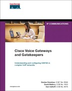
SIP entities can send additional messages in response to a method; these responses are listed in Table 4-1. Responses to SIP methods fall into six categories. The 100 Series designates informational or provisional responses, such as 100 for Trying, and 180 for Alerting. A 200 Series response means that the request was successful; it includes 200 for OK, and 202 for Accepted. The 300 Series redirects the user to a different location for the called endpoint. Examples include 301 for Moved Permanently and 302 for Moved Temporarily. The 400 Series of responses indicate a request failure, such as 404 User Not Found and 480 Temporarily Unavailable. A 500 Series response is received due to a server failure, such as 500 for Server Internal Error or 503 for Service Unavailable. The 600 Series is used for a global failure, including 603 when the call is declined.

*URI = uniform resource identifier
Example 4-1 shows a SIP INVITE message and explains the different fields. This call is from an IP phone in a CME network to an IP phone in a CallManager network. Neither phone is a SIP endpoint—the IP addresses listed are for the gateway and CallManager. A SIP trunk exists between CallManager and the gateway/CME.
Example 4-1. SIP INVITE Message
SIP-GW#debug ccsip messages
Sent:
!Request-URI (Uniform Resource Identifier) field
!This is the SIP address, or SIP URL, that the INVITE is sent to
INVITE sip:[email protected]:5060 SIP/2.0
!Each device that handles the packet adds its IP address to the VIA field
Via: SIP/2.0/UDP 10.6.3.1:5060;branch=z9hG4bKA1798
!The calling party. A tag identifies this series of messages
From: <sip:[email protected]>;tag=105741C-1D5E
!The called party
To: <sip:[email protected]>
Date: Fri, 06 Jan 2006 05:35:01 GMT
!Unique identifier for this call
Call-ID: [email protected]
!Extensions supported include reliable provisional responses and timer refreshes
Supported: 100rel, timer
!Minimum value for session interval
Min-SE: 1800
Cisco-Guid: 3892269682-738988502-2150410557-1198695355
!Identifies the device that originated the INVITE
User-Agent: Cisco-SIPGateway/IOS-12.x
!List of methods that are supported
Allow: INVITE, OPTIONS, BYE, CANCEL, ACK, PRACK, COMET, REFER, SUBSCRIBE, NOTIFY,
INFO, UPDATE, REGISTER
!Identifies call sequence number and method for this call
CSeq: 101 INVITE
!Max number of proxies or gateways that can forward this message
Max-Forwards: 70
Remote-Party-ID: <sip:[email protected]>;party=calling;screen=no;privacy=off
Timestamp: 1014960901
!Identifies the user agent client, for return messages
Contact: <sip:[email protected]:5060>
Expires: 180
Allow-Events: telephone-event
!This INVITE carries an SDP message
Content-Type: application/sdp
Content-Length: 202
SIP uses SDP to exchange information about endpoint capabilities and negotiate call features. This sample INVITE contains SDP information. The SDP part of a SIP message has standard fields, as shown in Example 4-2. This is the continuation of the INVITE message in Example 4-1. The SDP fields have the following meanings:
• v—Tells the SDP version
• o—Lists the organization of the calling party
• s—Describes the SDP message
• c—Lists the IP address of the originator
• t—Tells the timer value
• m—Describes the media that the originator expects
• a—Gives the media attributes
Example 4-2. SIP SDP Message Contents
v=0
o=CiscoSystemsSIP-GW-UserAgent 7181 811 IN IP4 10.6.3.1
s=SIP Call
c=IN IP4 10.6.3.1
t=0 0
m=audio 18990 RT
SIP-CME#P/AVP 0 19
c=IN IP4 10.6.3.1
a=rtpmap:0 PCMU/8000
a=rtpmap:19 CN/8000
a=ptime:20
Continuing the call, the called side (the UAS) returns a provisional response 100 Trying, shown in Example 4-3. Note that the call sequence number, 101, and the method type it is responding to, INVITE, are sent in each message.
Example 4-3. SIP “Trying” Response
Received:
!"Trying" indicates that the gateway has received the INVITE
SIP/2.0 100 Trying
Via: SIP/2.0/UDP 10.6.3.1:5060;branch=z9hG4bKA1798
From: <sip:[email protected]>;tag=105741C-1D5E
!A tag is added by the UAS to identify this series of messages
To: <sip:[email protected]>;tag=16777231
Date: Fri, 06 Jan 2006 5:35:10 GMT
Call-ID: [email protected]
Timestamp: 1014960901
CSeq: 101 INVITE
Allow-Events: telephone-event
Content-Length: 0
In Example 4-4, the UAS sends a 180 Ringing response to indicate that the remote phone is ringing.
Example 4-4. SIP Ringing Response
Received:
! Ringing indicates that the called phone is being alerted
SIP/2.0 180 Ringing
Via: SIP/2.0/UDP 10.6.3.1:5060;branch=z9hG4bKA1798
From: <sip:[email protected]>;tag=105741C-1D5E
To: <sip:[email protected]>;tag=16777231
Date: Fri, 06 Jan 2006 5:35:10 GMT
Call-ID: [email protected]
Timestamp: 1014960901
CSeq: 101 INVITE
Allow: INVITE, OPTIONS, BYE, CANCEL, ACK, PRACK
Allow-Events: telephone-event
Remote-Party-ID: <sip:[email protected]>;party=called;screen=no;privacy=off
Contact: <sip:[email protected]:5060>
Content-Length: 0
The remote phone has picked up the call, so a 200 OK response is sent, as shown in Example 4-5.
Received:
! OK indicates that the called phone has answered
SIP/2.0 200 OK
Via: SIP/2.0/UDP 10.6.3.1:5060;branch=z9hG4bKA1798
From: <sip:[email protected]>;tag=105741C-1D5E
To: <sip:[email protected]>;tag=16777231
Date: Fri, 06 Jan 2006 5:35:12 GMT
Call-ID: [email protected]
0Timestamp: 1014960901
CSeq: 101 INVITE
Allow: INVITE, OPTIONS, BYE, CANCEL, ACK, PRACK
Allow-Events: telephone-event
Remote-Party-ID: <sip:[email protected]>;party=called;screen=yes;privacy=off
Contact: <sip:[email protected]:5060>
Content-Type: application/sdp
Content-Length: 221
v=0
o=CiscoSystemsCCM-SIP 2000 1000 IN IP4 10.6.2.10
s=SIP Call
c=IN IP4 10.6.2.10
t=0 0
m=audio 24580 RTP/AVP 0 101
a=sendrecv
a=rtpmap:0 PCMU/8000
a=ptime:20
a=rtpmap:101 telephone-event/8000
a=fmtp:101 0-15
The UAC responds to the OK message with an ACK method, shown in Example 4-6. Now the call is established.
Sent:
ACK sip:[email protected]:5060 SIP/2.0
Via: SIP/2.0/UDP 10.6.3.1:5060;branch=z9hG4bKB1C57
From: <sip:[email protected]>;tag=105741C-1D5E
T0o: <sip:[email protected]>;tag=16777231
Date: Fri, 06 Jan 2006 5:35:13 GMT
Call-ID: [email protected]
Max-Forwards: 70
CSeq: 101 ACK
Content-Length: 0
SIP Call Flow
Basic SIP session setup involves a SIP UA client sending a request to the SIP URL of the called endpoint (UAS), inviting it to a session. If the UAC knows the IP address of the UAS, it can send the request. Otherwise, the UAC sends the request to a proxy or redirect server to locate the user. That server might forward the request to other servers until the user is located. After the SIP address is resolved to an IP address, the request is sent to the UAS. If the user takes the call, capabilities are negotiated and the call commences. If the user does not take the call, it can be forwarded to voice mail or another number. The following sections outline various scenarios in more detail.
Call Flow Between Two SIP Gateways
Cisco routers, including CME routers, can act as SIP gateways for calls that originate from non-SIP phones. The gateways function as SIP UAs and set up a SIP session between them for each call. Figure 4-1 shows two routers handling analog phones, using SIP between them. In this example, SIP GW-A originates the calls and acts as a UAC, and SIP GW-B acts as a UAS. The signaling from the PBX to the gateway is just normal analog call signaling. Only the two gateways exchange SIP messages.
In Figure 4-1, the analog phone on the left initiates a call to the analog phone on the right.
Figure 4-1. Call Flow Between Two SIP Gateways
After the first phone initiates the call, the call flow proceeds as follows:
1 The PBX sends a call setup signal to GW-A, which then sends a SIP INVITE message to GW-B. This INVITE contains SDP information for capabilities negotiation. GW-A also sends a Call Proceeding message to the PBX.
2 GW-B exchanges call setup message with its PBX and sends SIP responses 100 (Trying) and 180 (Ringing) to GW-A.
3 GW-A translates these messages into analog signaling messages for its PBX.
4 When the user on the right picks up the call, his PBX sends a Connect message to GW-B, which then forwards a SIP 200 (OK) response to GW-A. This OK response contains SDP information with the capabilities that both devices support.
5 GW-A delivers a Connect message to its PBX. When the PBX acknowledges that with a Connect ACK, it sends a SIP ACK message to GW-B.
6 GW-B sends a Connect acknowledgement to its PBX, and the call is active. At this point, normal voice steams exist between the two phones and the gateways, and RTP voice streams exist between the two gateways.
7 The user on the left hangs up the phone. His PBX sends a Call Disconnect message to GW-A. GW-A then sends a SIP BYE message to GW-B and a Release message to the PBX. The PBX responds with a Release Complete message.
8 GW-B sends a Call Disconnect message to its PBX, which responds with a Release message.
9 GW-B forwards a SIP 200 (OK) response to GW-A and a Release Complete message to its PBX. The call is now completely terminated.
Call Flow Using a Proxy Server
SIP UAs register with a proxy server or a registrar. Proxy servers then act as an intermediary for SIP calls. Cisco routers that are acting as SIP gateways can use the services of a SIP proxy server, either contacting the server or receiving requests from it. They can additionally register E.164 numbers with a proxy server or a registrar.
Proxy servers can either leave the signaling path when the call is connected or can enable “Record-route” to stay in the signaling path. If Record-route is disabled, the proxy server does not know of any changes to the call or when the call is disconnected. Figure 4-2 shows call flow when Record-route is disabled.
In Figure 4-2, a SIP endpoint places a call using a proxy server. The figure shows several types of endpoints:
• A PC and a PDA running a SIP application
• A SIP phone
• A cell phone that uses SIP
Figure 4-2. SIP Call Flow Using a Proxy Server
In Figure 4-2, one of these endpoints places a call to an analog phone behind SIP gateway GW-B. The call flow proceeds as follows:
1 The UAC sends an INVITE to its proxy server. In this INVITE, the Request-URI field contains the address of the called phone number as part of the SIP address. SDP information is included with this INVITE.
2 The proxy server creates a new INVITE, copying the information from the old INVITE, but replacing the Request-URI with the address of GW-B—the UAS.
3 When GW-B receives the INVITE, it initiates a call setup with the PBX. It sends a SIP response 100 (Trying) to the proxy server which, in this example, sends a 100 response to the SIP UAC. The proxy server is not required to send this response.
4 The PBX sets up an analog call with the end user and sends call progress messages to GW-B. When GW-B receives the Alerting message, it sends a SIP 180 (Ringing) message to the proxy server. The proxy server sends the same message to the UAC.
5 When the end user picks up the phone, the PBX sends a Connect message to GW-B. GW-B then sends a SIP 200 (OK) response to the proxy server, which sends it to the UAC. SDP information for the remote end is included in this OK response. The proxy server is not configured to be stateful—that is, Record Route is disabled. Therefore, the proxy server leaves the signaling path, and all further SIP signaling is directly between the UAC and GW-B.
6 The SIP UAC acknowledges the OK response, and a two-way RTP stream is established between the UAC and GW-B, the UAS. A two-way voice stream is established between GW-B and the PBX.
7 When the UAC hangs up, it exchanges SIP BYE and OK signals with GW-B. GW-B terminates the call with the PBX.
Call Flow Using Multiple Servers
SIP UAs and SIP proxy servers can contact a redirect server to determine where to send an INVITE. They typically do this when the called number is outside the local domain. The redirect server returns the most detailed information it has—either endpoint location(s) or the location of the next-hop server. Then it relies on the proxy server or UAC to route its INVITE appropriately.
Figure 4-3 shows the call flow in a more complex network with registrar, redirect, and proxy servers. (Recall that these are functional units and can all reside in the same device.) The figure shows the messages that are necessary to route the initial INVITE method to the UAS. After GW-B, the UAS, receives the INVITE, call flow is similar to the previous examples.
Figure 4-3. SIP Call Flow with Multiple Servers

In Figure 4-3, one of the SIP endpoints in Network A calls an analog phone behind gateway GW-B in Network B. The following steps take place:
1 The gateway, GW-B, registers the E.164 phone numbers of its analog phones with the registrar server.
2 The registrar server replies with a 200 (OK) response.
3 The UAC sends an INVITE method to its proxy server, Proxy-A.
4 The proxy server recognizes that the destination number is outside its domain. It sends the INVITE to the redirect server.
5 The redirect server replies with a 300-series message listing the SIP address of the next-hop proxy server, Proxy-B.
6 Proxy-A sends an INVITE message to Proxy-B.
7 Proxy-B requests the location of the called number from its registrar server.
8 The registrar server responds with the SIP address of GW-B.
9 Proxy-B sends an INVITE to GW-B.
Following these steps, GW-B sets up the call with the PBX. It sends responses to Proxy-B, which forwards them through Proxy-A to the calling endpoint. If Record-route is enabled, all further signaling goes through the proxies. If not, call signaling proceeds as shown in Figure 4-2.
Call Flow Using Cisco CallManager 5.x
CallManager 5.x supports SIP phones and is an integral part of a SIP network. It can play different roles, such as registrar server and B2BUA.
Figure 4-4 illustrates a call flow scenario with CallManager acting as a B2BUA.
Figure 4-4. Call Flow with CallManager 5.x
In Figure 4-4, a SIP phone is registered to a CallManager. The SIP phone places a call to an analog phone off a PBX behind the router/gateway GW-B. A SIP trunk exists between CallManager and the gateway. CallManager acts as a B2BUA—it terminates each leg of the call during the signaling phases, yet it allows the RTP stream to go directly between the two endpoints. This is accomplished by the way SDP information is sent.
1 A SIP phone that is registered to CallManager calls the analog phone. It sends an INVITE containing standard SDP information to CallManager. CallManager responds with a 100 Trying message. In this step, CallManager is acting as a UAS.
2 CallManager sends an INVITE over its SIP trunk to the remote SIP gateway, GW-B. This INVITE has a different Call-ID number than the one from the phone. In addition, this INVITE does not contain SDP fields. CallManager acts as a UAC in this step.
3 GW-B answers with a 100 Trying message and initiates a call to the PBX. (That signaling is not shown.) GW-B sends its SDP parameters in a 183 Session Progress message to CallManager. Included in this are the session parameters that the gateway supports.
4 CallManager sends a 183 Session Progress message to the SIP phone. This message contains an SDP portion with the capabilities that both endpoints support. For instance, suppose that the original SDP message of the phone indicated that it supported G.711 and G.729 codecs, but the gateway SDP message said that it supported only G.729. In that case, the 183 message from CallManager to the phone would list only G.729. It would also list the IP address of GW-B as the originator address in SDP field ‘c.’
5 When the analog phone picks up, GW-B sends a 200 OK message containing its SDP information. CallManager acknowledges it with an ACK that contains the SDP information that both endpoints support. The IP address of the SIP phone is also included as the originator address in the SDP field ‘c.’
6 CallManager sends a 200 OK message with SDP information to the phone. The phone acknowledges that message. Now that each endpoint has the IP address of the other, the two can establish an RTP stream between them for the duration of the call.
7 In Figure 4-4, the analog phone hangs up, so GW-B sends a SIP BYE method to CallManager.
8 CallManager replies with a 200 OK response and then sends a BYE to the SIP phone. The phone responds with a 200 OK message.
SIP Pros and Cons
People have high expectations for SIP. They hope it will enable advanced, anywhere, anytime multimedia communication. However, SIP is basically just another call control protocol, with its pros and cons. The following sections list a few of each.
Pros
• SIP works independently of the type of session, or the media used, giving it flexibility.
• It is an open standard, allowing multivendor support and integration. Applications can be written to customize SIP uses.
• SIP messages are clear text, making troubleshooting easier.
• SIP can accommodate multiple users with differing capabilities. For instance, in a conference that has some users with video capability and some only with audio capability, the video users can see each other. They do not have to drop down to audio only, as with other protocols.
Cons
• Processing text messages puts a higher load on gateways. The router must translate that text into a language that the router can understand. Code for this must be in the Cisco IOS.
• SIP is a fairly new protocol, so fewer people understand it than the older protocols. Be sure you have trained support personnel if you intend to implement SIP within your network.
• When you are using both SIP and SCCP phones on the same network, you must convert between in-band and out-of-band DTMF tones.
• SIP features are still being developed, and many vendors have proprietary implementations of the protocol.
When to Use SIP
SIP is the protocol of choice when you want to integrate multiple types of media. For example, perhaps you get an instant message on your phone screen that you want to respond to verbally. You start to press the button to call the IM sender, but you see that the sender has set his status to “Don't call me,” so you refrain. Later, you would like to have a videoconference with three other people, but you notice that one of them has his phone off-hook. The other two join you, one as video and the other as audio only. You send a text message to the IP phone of the third person, asking him to join when he can. This might sound like the office of the future, but it is becoming reality.
You can use SIP trunks even without native SIP phones. You might choose them because of the simple session setup mechanism for SIP. For instance, you can use a SIP trunk between gateways with toll bypass. When you use SIP with CallManager or CME, you are not limited to Cisco-brand IP phones. You can also use other commercially available, and perhaps lower-priced, SIP phones. Be aware that CallManager might not be able to provide all the features for these phones that it can for a Cisco-brand SIP phone.
Before you implement a SIP network, plan its integration into your existing network. Determine exactly what you want to accomplish and how you will accomplish it. Remember also that you need to either find people who are knowledgeable about SIP or train your staff.
Dial Plan Considerations
SIP dial plan considerations are similar to those for an H.323 gateway, because dial peers control gateway call routing. You must configure dial peers to forward calls out of the gateway. You can forward calls to CallManager using a Voice over Internet Protocol (VoIP) dial peer, to the PSTN as a plain old telephone service (POTS) dial peer, to another gateway using a VoIP dial peer, or to directly connected voice ports as POTS dial peers.
In a voice network that has CallManagers and SIP gateways, it is important to understand the interaction between the two, because different versions of CallManager have different SIP capabilities. CallManager versions before 5.x can only have a SIP trunk to a gateway or other servers. CallManager 5.x and above also acts as a SIP B2BUA and allows SIP phones to register to it. It also can do domain routing for SIP calls. A new menu, SIP Route Pattern, allows you to configure SIP URI dialing. Therefore, your dial plan must take into account the CallManager version. No matter which version of CallManager you use, you configure a dial plan to send calls to the SIP trunk when needed. CallManager appears to the SIP gateway as a SIP-enabled VoIP dial peer.
Another consideration in SIP networks is where the dial plan will reside. The default behavior of SIP is to push down the dial plan to each endpoint. When a user dials digits on the phone, the phone compares those numbers against its internal dial plan. If the phone finds a match, it sends an INVITE. Otherwise, it must wait for the interdigit timer to expire before playing a reorder tone. The alternative is to use the Key Press Markup Language (KPML). When you use KPML, the SIP phone sends each digit to CallManager, similar to the way SCCP phones behave. CallManager can instruct the phone to play a reorder tone immediately if an incorrect number is dialed, or it can route the call as soon as enough digits are dialed. If you do not use KPML, you must configure SIP dial rules.
In your dial planning, consider the need to configure the gateway for such options as number translations or other digit manipulations, or call restrictions. If you are using SRST, be sure that the dial plan will work both with and without CallManager and, if possible, any SIP servers in the network. You need at least one dial peer with a destination pattern for routing outgoing calls. Default incoming POTS and VoIP dial peers are available, but you should specifically configure dial peers for incoming calls if you need a nondefault configuration.
As with H.323, SIP gateway configuration can become complex in a large network. You must configure each gateway with the information you need to route calls. Proxy, registrar, redirect, and DNS servers can help the network scale by providing dial plan resolution. This simplifies the gateway configuration.
Implementing SIP Gateways
Configuring a SIP gateway can be as simple as configuring SIP VoIP dial peers or as complex as tweaking SIP settings and timers. Gateway SIP configuration is done in three basic places: on dial peers, under SIP UA configuration mode, and under voice service VoIP configuration mode. The following sections discuss the types of configuration you can accomplish in each mode.
SIP Dial Peer Configuration
A basic SIP gateway configuration consists of simply adding one line under a VoIP dial peer configuration: session protocol sipv2. You can use additional dial peer settings; the exact options and commands vary by Cisco IOS version. For instance, to allow SIP calls to be hairpinned from one VoIP dial peer to the other, use the redirect ip2ip command. SIP supports both consultative and blind call transfers from Cisco gateways. It also supports call forwarding from IP phones that are registered with the gateway as e-phones. This capability is enabled per dial peer with the application session command in dial-peer configuration mode.
To change the transport protocol (UDP is the default), use the session transport [udp | tcp] command. SIP can switch from using UDP to TCP when a voice packet gets within 200 bytes of the maximum transmission unit (MTU) to avoid UDP fragmentation. To configure this for a specific dial peer, use the voice-class sip transport switch udp tcp command. You can also configure this globally under voice service configuration mode.
Example 4-7 shows the configuration of two SIP dial peers. On the first dial peer, the transport protocol is changed from the default UDP to TCP (an optional step). On the second dial peer, the configuration shows enabling switching from UDP to TCP for large packets.
Example 4-7. Configuring a SIP Dial Peer
SIP-GW(config)#dial-peer voice 3401 voip
SIP-GW(config-dial-peer)#session target ipv4:10.6.2.1
SIP-GW(config-dial-peer)#session protocol sipv2
SIP-GW(config-dial-peer)#session transport tcp
!
SIP-GW(config)#dial-peer voice 4404 voip
SIP-GW(config-dial-peer)#session target ipv4:10.7.1.1
SIP-GW(config-dial-peer)#session protocol sipv2
SIP-GW(config-dial-peer)#voice-class sip transport switch udp tcp
SIP-GW(config-dial-peer)#destination-pattern 4404...
SIP UA Configuration
The SIP UA does not require configuration to function, but you might want to make some adjustments. Enter UA configuration mode by issuing the sip-ua command. As with dial peers, the options vary by Cisco IOS and device. Table 4-2 shows some common UA commands.
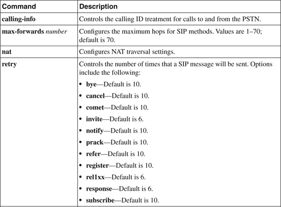
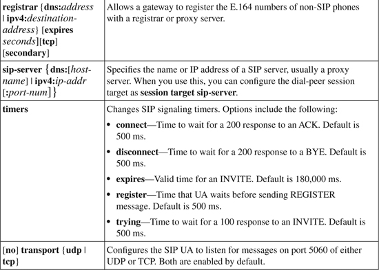
Example 4-8 shows a SIP UA configuration. The gateway is configured to register its analog phones with redundant servers, the IP address of the proxy server is specified, the maximum number of hops for SIP methods is reduced to 10, and the gateway is limited to listening for TCP SIP messages. The configuration is partially verified by using the show sip-ua status command. The configured E.164 phone number registration is verified with the show sip-ua register status command.
Example 4-8. SIP UA Configuration
SIP-GW(config)#sip-ua
SIP-GW(config-sip-ua)#registrar ipv4:10.30.25.250 tcp
SIP-GW(config-sip-ua)#registrar ipv4:10.30.25.251 tcp secondary
SIP-GW(config-sip-ua)#sip-server ipv4:10.30.25.252
SIP-GW(config-sip-ua)#max-forwards 10
SIP-GW(config-sip-ua)#no transport udp
!
SIP-GW#show sip-ua status
SIP User Agent Status
SIP User Agent for UDP : DISABLED
SIP User Agent for TCP : ENABLED
SIP User Agent bind status(signaling): DISABLED
SIP User Agent bind status(media): DISABLED
SIP early-media for 180 responses with SDP: ENABLED
SIP max-forwards : 10
SIP DNS SRV version: 2 (rfc 2782)
NAT Settings for the SIP-UA
Role in SDP: NONE
Check media source packets: DISABLED
Maximum duration for a telephone-event in NOTIFYs: 1000 ms
SIP support for ISDN SUSPEND/RESUME: ENABLED
Redirection (3xx) message handling: ENABLED
Reason Header will override Response/Request Codes: DISABLED
SDP application configuration:
Version line (v=) required
Owner line (o=) required
Timespec line (t=) required
Media supported: audio image
Network types supported: IN
Address types supported: IP4
Transport types supported: RTP/AVP udptl
!
SIP-GW#show sip-ua register status
Line peer expires(sec) registered
============ ============= ============ ===========
4101 20001 118 yes
4102 20003 118 yes
4103 20005 118 yes
4104 20007 118 yes
SIP Voice Service Configuration
The voice service configuration mode is used for voice-related commands that affect the entire gateway. Enter this mode by issuing the voice service voip command. In this mode, you can allow hairpinned calls for all dial peers with the redirect ip2ip command. (You can also issue this command under dial-peer configuration mode. Then it affects only those dial peers.)
You can enter the SIP submode with the sip command from voice service mode. You can do several SIP-specific configurations from this mode. Table 4-3 lists some of these; specific options vary by Cisco IOS version and device.
Table 4-3. SIP Voice Service Configuration Commands
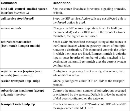
Example 4-9 shows a gateway that has been configured to hair-pin calls for all dial peers. The source IP address for all SIP signaling traffic has been set to Loopback 0, and this gateway has been configured to act as a registrar server. You can verify the interface binding with the show sip-ua status command.
Example 4-9. SIP Voice Service Configuration
SIP-GW(config)#voice service voip
SIP-GW(conf-voi-serv)#redirect ip2ip
SIP-GW(conf-voi-serv)#sip
SIP-GW(conf-serv-sip)#bind control source-interface lo0
SIP-GW(conf-serv-sip)#registrar server expires max 1500 min 500
Toll Bypass
You use toll bypass to send calls between different sites over a packet network rather than over the PSTN. Because this bypasses the PSTN, it also bypasses any long-distance toll charges. Cisco routers, functioning as edge gateways, can use SIP to pass voice traffic between them. This traffic is typically from analog phones, such as those connected to a PBX, but it can be from IP or SIP phones. Figure 4-1 shows this type of setup.
Configuring the routers for toll bypass involves two components. First, you must configure connection(s) to the internal voice network. This might be a PRI to a PBX, for instance. You must configure both the physical links and the appropriate dial peers. Second, you must configure the connection to the other router. This involves configuring the physical link and at least one SIP VoIP dial peer pointing to the remote SIP router. You configure the dial peers and gateways as detailed in the previous sections of this chapter.
Registering with CallManager
CallManager versions 4.x can register a SIP trunk connecting to a remote gateway, a proxy server, or CallManager Express. The trunk is referred to as a signaling interface. CallManager 5.x can register SIP phones, in addition to SIP trunks. Trunks can point to other Cisco CallManager clusters, also.
Configuring a SIP Trunk with CallManager 4.x
The following steps show how to create a SIP trunk on CallManager 4.x. The menus on other versions of CallManager might vary slightly, but the process is similar.
Step 1. To add a new trunk, select the Device menu, and then select the Trunk link. At the Find and List Trunks screen, shown in Figure 4-5, click the link for Add a New Trunk.
Step 2. On the next screen, shown in Figure 4-6, select SIP Trunk as the Trunk type. Notice that Device Protocol is automatically set to SIP. Click the Next button.
Figure 4-5. CallManager Find and List Trunks Screen
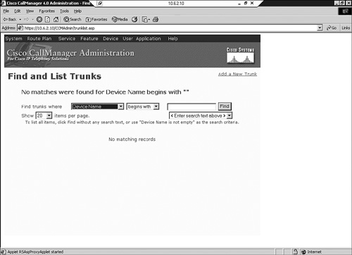
Figure 4-6. CallManager SIP Trunk Creation

Step 3. The Trunk Configuration screen, shown in Figure 4-7, appears next. Enter the name of the device at the other end of the trunk, and optionally a description. You must select a Device Pool. Then designate whether calls to this trunk are OnNet or OffNet, or let the system decide. Note that a media termination point (MTP) is required. This is to translate DTMF signals between SIP and SCCP phones. For more information, see the later section, “DTMF Relay.”
Figure 4-7. SIP Trunk Configuration in CallManager
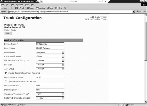
Step 4. On this same screen, enter the destination address of the trunk.
Step 5. The next options in the Trunk Configuration screen are for the Destination Port number, the Incoming Port number, and the Outgoing Transport Type (Layer 4 protocol). The default destination port for SIP is 5060, and it is typically left at that. CallManager can have multiple SIP signaling interfaces. You must use a unique incoming port for each signaling interface in CCM 4.x. Not shown in Figure 4-7 are settings for incoming and outgoing calls, further down on the screen.
Step 6. When you are finished with the configuration, click Insert. You are then prompted to reset the trunk.
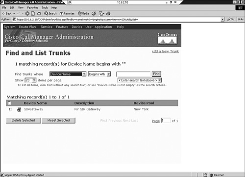
Step 7. You can verify your trunk configuration by going back to the Find and List Trunks page. Click the Find button, and verify that your new trunk is there, as shown in Figure 4-8. After you have created the trunk, you can assign route patterns, list, or groups to it as normal.
Figure 4-8. Verifying a SIP Trunk in CallManager
Configuring a SIP Trunk with CallManager 5.x
The process that you use to register a SIP trunk with CallManager 5.x is slightly different from the CallManager 4.x process. For instance, an MTP is not required with CallManager 5.x if the endpoints can negotiate using out-of-band DTMF relay. Multiple trunks can have the same incoming port number.
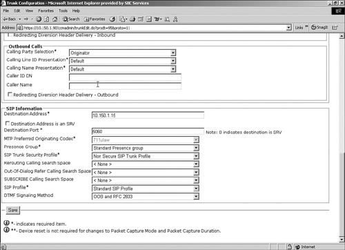
To begin adding a SIP trunk in CCM 5, follow Steps 1 and 2 in the CallManager 4.x process. The next screen, the Trunk Configuration screen, has some different fields, and some fields are in different positions in CallManager 5.x. Figures 4-9, 4-10, and 4-11 show this Trunk Configuration screen. Some items to note are that the MTP might not be required and is not checked automatically. Some SIP-specific fields have been added, such as Presence Group, SIP Trunk Security Profile, SIP Profile, and SUBSCRIBE Calling Search Space.
Figure 4-9. Configuring a SIP Trunk in CCM 5

Figure 4-10. Configuring a SIP Trunk in CCM 5 (continued)

Figure 4-11. Configuring a SIP Trunk in CCM 5 (continued)
When you are finished configuring the trunk, you must save it by clicking the Save button on the bottom of the screen or the disk icon at the top of the screen. You can verify SIP trunk configuration for CallManager 5.x by using the same method that you used for CallManager 4.x—by using the Find button at the Find and List Trunks page.
Configuring the Gateway for a CallManager Trunk
Regardless of the CallManager version you use, the gateway sees it as a SIP dial peer. For redundancy, you can configure a dial peer for each CCM in the cluster, using preference to determine their order of use. Example 4-7 (shown previously) demonstrates the configuration for a basic SIP dial peer.
DTMF Relay
DTMF tones are the tones that are generated when a telephone key is pressed on a touchtone phone. Sometimes the called endpoint needs to hear those tones, such as when you enter digits during the call in response to a menu. Low-bandwidth codecs can distort the sound, however. DTMF relay allows that tone information to be reliably passed from one endpoint to the other. By default, SIP uses in-band signaling, sending the DTMF information in the voice stream. However, you can configure it to use RTP-NTE, SIP INFO messages, SIP NOTIFY messages, or KPML for transmitting DTMF tone information.
RTP-NTE is an in-band DTMF relay method, which uses RTP Named Telephony Event (NTE) packets to carry DTMF information instead of voice. If RTP-NTE is configured, SDP is used to negotiate the payload type value for NTE packets and the events that will be sent using NTE.
RTP-NTE can cause problems communicating with SCCP phones, which use only out-of-band DTMF relay. In a CallManager 4.x network with SCCP phones, you must provision an MTP for calls that traverse the SIP trunk. This MTP translates between in-band and out-of-band DTMF signals. You must configure a separate MTP for each side of the SIP trunk. You can do this MTP in hardware, or in software on CallManager.
Cisco has two out-of-band procedures for DTMF relay. One uses SIP INFO methods, and the other uses SIP NOTIFY methods. The SIP INFO method sends DTMF digits in INFO messages. It is always enabled. When a gateway receives an INFO message containing DTMF relay information, it sends the corresponding tone.
NOTIFY-based out-of-band DTMF relay is negotiated by including a Call-Info field in the SIP INVITE and response messages. This field indicates an ability to use NOTIFY for DTMF tones and the duration of each tone in milliseconds. Using this method can help SIP gateways interoperate with Skinny phones. You can also use it for analog phones that are connected to Foreign Exchange Station (FXS) ports on the gateway.
When a DTMF tone is generated, the gateway sends a NOTIFY message to the terminating gateway. When that gateways receives the NOTIFY, it responds with SIP 200 OK and plays the DTMF tone. To configure the DTMF relay type, use the dtmf-relay command in dial-peer configuration mode. To optionally configure the interval between NOTIFY messages for a single DTMF event, use the notify telephone-event max-duration milliseconds command in SIP UA configuration mode. The default is 2000 msec; the lowest value between two SIP peers is the one chosen.
Example 4-10 shows these commands. Notice that two types of DTMF relay are configured. The router prefers SIP-NOTIFY but uses RTP-NTE if the other side does not support SIP-NOTIFY. If no DTMF relay method is configured, the tones are sent in-band.
Example 4-10. Configuring NOTIFY-Based DTMF Relay
!Setting the NOTIFY interval
SIP-GW(config)#sip-ua
SIP-GW(config-sip-ua)#notify telephone-event max-duration 1000
SIP-GW(config-sip-ua)#exit
!
!Setting NOTIFY-based out-of-band DTMF relay
SIP-GW(config)#dial-peer voice 3400 voip
SIP-GW(config-dial-peer)#dtmf-relay ?
cisco-rtp Cisco Proprietary RTP
h245-alphanumeric DTMF Relay via H245 Alphanumeric IE
h245-signal DTMF Relay via H245 Signal IE
rtp-nte RTP Named Telephone Event RFC 2833
sip-notify DTMF Relay via SIP NOTIFY messages
SIP-GW(config-dial-peer)#dtmf-relay sip-notify rtp-nte
KPML is another way for SIP phones to send dialed-digit information, as described previously in the “Dial Plan Considerations” section. Like SIP-NOTIFY, KPML uses a NOTIFY message to transmit each digit.
Securing SIP Gateways
Your SIP gateway, as part of your IP network, should conform to your company security policy. Deployment of basic items, such as user control and authentication, access-control lists, and physical security, should be standard. The SIP network, like most of your user devices, should be on a LAN using private IP addresses, with strong perimeter security.
Because SIP messages contain IP addresses in several different locations, it is important to use a firewall that supports SIP. Cisco IOS firewalls, PIX firewalls, and Adaptive Security Appliance (ASA) devices are all able to inspect the SIP application data and maintain call flow information.
SIP supports some authentication, authorization, and accounting (AAA) mechanisms to help authenticate communications between UAs, servers, and gateways. You can use RADIUS to preauthenticate calls. The gateway forwards incoming call information to a RADIUS server, which must authenticate it before connecting the call. To enable AAA for SIP calls, you must use the normal AAA configuration on the gateway and the RADIUS server. In addition, at global configuration mode, issue the aaa preauth command to enter AAA preauthentication configuration mode. Specify the RADIUS server with the command group {radius | groupname}.
You can also use HTTP Authentication Digest. UAs, proxy servers, and redirect servers can request authentication before they process a SIP message. Gateways can respond to authentication challenges and can respond on behalf of non-SIP phones that they have registered to a SIP server. SIP defines authentication and authorization fields that can be present in the message header. A server that receives a message—such as an INVITE—without authentication credentials issues a challenge. The response includes an authorization field with an MD5 hash and other credentials. To configure a gateway to use HTTP Authentication Digest, give the following command in each dial peer or SIP-UA configuration mode: authentication username username password password [realm realm]. Username is the name of the user that will be authenticating, password is the shared password, and realm is an optional entry that lets you configure multiple username/password combinations. The realm is included in the challenge, so the response will include credentials for that specific realm.
To provide a more secure, encrypted transport mechanism for SIP messages, Cisco IPT devices have added support for the TLS protocol.
Allowing H.323 to SIP Connections
SIP and H.323 dial peers can be configured on the same gateway, but call routing between the two types of dial peers is disabled by default. To enable this routing, enter voice service configuration mode and issue the command allow-connections from-type to to-type. Options for both the from-type and the to-type are h323 and sip. Example 4-11 shows a router that is configured to allow multiple types of VoIP connections.
Example 4-11. Configuring H.323 to SIP Connections
H323-SIP-GW(config)#voice service voip
H323-SIP-GW (conf-voi-serv)# allow-connections h323 to h323
H323-SIP-GW (conf-voi-serv)# allow-connections h323 to sip
H323-SIP-GW (conf-voi-serv)# allow-connections sip to h323
H323-SIP-GW (conf-voi-serv)# allow-connections sip to sip
Troubleshooting Tools
If calls cannot be made between SIP gateways or over SIP trunks, dial peer configuration is one of the first places to check. Make sure that the dial peer is configured to use SIP and that both devices are using the same transport protocol and DTMF relay method. Make sure that destination patterns and session targets are correct, also.
Several show commands can troubleshoot and monitor the SIP UA function of the gateway. Example 4-12 lists them; options can vary by Cisco IOS and device.
Example 4-12. show sip-ua Command Options
SIP-GW#show sip-ua ?
calls Display Active SIP Calls
connections Display SIP Connections
map Display SIP status code to PSTN cause mapping table & vice versa
min-se Display Min-SE value
mwi Display SIP MWI server info
register Display SIP Register status
retry Display SIP Protocol Retry Counts
service Display SIP submode Shutdown status
statistics Display SIP UA Statistics
status Display SIP UA Listener Status
timers Display SIP Protocol Timers
The show sip-ua connections {udp|tcp} command gives you information on active connections, including those with errors. To stop a problem connection, use the clear sip-ua {udp | tcp} [connection id number] [target ipv4:ip-address] command.
To ensure that the SIP is enabled on the gateway, use the show sip-ua service command. You should get the following result:
SIP-GW#show sip-ua service
SIP Service is up
The show sip-ua statistics command provides statistics on each type of method and response, errors, and total SIP traffic information. You can reset these counters with the clear sip-ua statistics command.
The show sip-ua status command can be useful in troubleshooting, also. Output from this command was shown previously in Example 4-13.
To debug SIP messages, use the debug ccsip command. This command has several options, as Example 4-13 shows. Use messages to see the SIP method and response messages, as shown previously in Example 4-1. The media option shows RTP information. Your options might vary by Cisco IOS and device.
Example 4-13. debug ccsip Command Options
SIP-GW#debug ccsip ?
all Enable all SIP debugging traces
calls Enable CCSIP SPI calls debugging trace
error Enable SIP error debugging trace
events Enable SIP events debugging trace
info Enable SIP info debugging trace
media Enable SIP media debugging trace
messages Enable CCSIP SPI messages debugging trace
preauth Enable SIP preauth debugging traces
states Enable CCSIP SPI states debugging trace
transport Enable SIP transport debugging traces
Case Study: Configuring SIP Between a Gateway and CallManager 5.x
In this case study, SIP is being introduced into the New York and Shanghai networks. The locations will use both SIP and SCCP phones, and a SIP trunk will be configured between the New York CallManager cluster and the Shanghai gateway, shown in Figure 4-12. CallManager 5.x is used to register the SIP phones. The preferred DTMF relay method will be SIP-NOTIFY, but RTP-NTE will be accepted as a second choice.
For redundancy, the Shanghai gateway has dial peers to two of the CallManager servers. One CallManager IP address is configured under the UA, to demonstrate that command. The gateway will register its network analog phones with registrar servers at 10.10.10.19 and 10.10.10.20. HTTP digest authentication is configured.
All SIP traffic will use interface Fa0/0 as its source IP address. Large packets will switch from UDP to TCP as their transport protocol to avoid UDP fragmentation.
Figure 4-12. SIP Case Study Network Diagram

Example 4-14 shows the configuration of SIP and the SIP trunk on the Shanghai gateway. POTS dial peers to connect to the PBX are not shown in this example. CallManager configuration is outside the scope of this case study.
Shanghai-GW(config)#sip-ua
Shanghai-GW(config-sip-ua)#sip-server ipv4:10.10.10.11
Shanghai-GW(config-sip-ua)#registrar ipv4:10.10.10.19
Shanghai-GW(config-sip-ua)#registrar ipv4:10.10.10.20 secondary
Shanghai-GW(config-sip-ua)#authentication username NYCServ1 password C1sc0 realm
NYC-SIP
!
Shanghai-GW(config)#voice service voip
Shanghai-GW(conf-voi-serv)#sip
Shanghai-GW(conf-serv-sip)#bind all source-interface fa0/0
Shanghai-GW(conf-serv-sip)#transport switch udp tcp
!
Shanghai-GW(config)#dial-peer voice 2121 voip
Shanghai-GW(config-dial-peer)#destination-pattern 21255521..
Shanghai-GW(config-dial-peer)#session target sip-server
Shanghai-GW(config-dial-peer)#session protocol sipv2
Shanghai-GW(config-dial-peer)#dtmf-relay sip-notify rtp-nte
Shanghai-GW(config-dial-peer)#preference 1
!
Shanghai-GW(config)#dial-peer voice 2122 voip
Shanghai-GW(config-dial-peer)#destination-pattern 21255521..
Shanghai-GW(config-dial-peer)#session target 10.10.10.12
Shanghai-GW(config-dial-peer)#session protocol sipv2
Shanghai-GW(config-dial-peer)#dtmf-relay sip-notify rtp-nte
Shanghai-GW(config-dial-peer)#preference 2
Review Questions
1 What do the acronyms UAC and UAS stand for? Define the difference between the two entities.
2 Name five types of SIP servers, and describe what they do.
3 Name the five types of SIP methods that Cisco routers can both generate and respond to. What is the purpose of each one?
4 What command configures a dial peer to use SIP in its communication with its VoIP peer?
5 How does CallManager 4.x interact with a SIP gateway?
6 What additional SIP capabilities does CallManager 5.x add?
7 Which Layer 4 protocol does SIP use by default, and what is the default port?
8 What is the function of the SDP in SIP call setup?