Chapter 18. Cisco Multiservice IP-to-IP Gateway
One of the latest buzzwords in Voice over IP (VoIP) infrastructure deployments is Session Border Controller (SBC). As VoIP deployments move from individual islands of voice networks to end-to-end voice solutions, SBCs become a crucial infrastructure device that sits on the border of two networks handling real-time voice and video sessions. Before SBCs, service providers implemented back-to-back time-division multiplexing (TDM) gateways when interconnecting with other service providers. They were able to create points of demarcations between the networks, but because of the involvement of the digital signal processors (DSP), not only was delay being introduced, but also degradation in the voice/fax quality because of the additional decoding and encoding of the voice/fax packets. Apart from creating points of demarcations, various other challenges arise when you interconnect two VoIP/video networks.
To benefit from low long-distance telephony charges, many enterprises have also started using IP interconnect services from service providers. SBCs are used between the two networks to handle their real-time communication needs. Cisco Multiservice IP-to-IP gateway (IPIPGW) is the Cisco Session Border Controller product that provides a toolkit of Cisco IOS features to resolve various interconnect problems.
This chapter helps you do the following:
• Understand the IPIPGW architecture
• Configure an IPIPGW
• Understand Voice Infrastructure and Application (VIA) zones
• Understand the features that are available on IPIPGWs
• Use show and debug commands
IP-to-IP Gateway Overview
VoIP has gained acceptance with enterprise, service provider, and commercial customers, and the migration of voice traffic from public switched telephone network (PSTN) to voice traffic over the IP network is underway. Increasing numbers of customers, looking for richer services than the PSTN can provide, are starting to interconnect their VoIP networks. However, interconnecting disparate VoIP networks has a new set of challenges that need to be dealt with. These new network requirements include the following:
• Creating proper points of demarcation between enterprises and service providers, primarily for providing security and collection of call detail records (CDRs) for voice quality statistics and billing.
• Hiding internal network topology from the peering partner or the outside world for security purposes.
• Providing interworking between H.323 and Session Initiation Protocol (SIP)
• Addressing various other challenges, such as transcoding media, routing VoIP traffic to traverse firewalls and Network Address Translation (NAT), ensuring quality of service (QoS), and employing call admission control (CAC).
Cisco Multiservice IP-to-IP Gateway
The Cisco Multiservice IPIPGW facilitates simple and cost-effective connectivity between independent VoIP and video networks. Designed to meet enterprise and service provider SBC needs, the Cisco Multiservice IPIPGW is an integrated Cisco IOS application that runs on the following platforms:
• Cisco 2800 series integrated services routers
• Cisco 3800 series integrated services routers
• Cisco 2600XM series multiservice platforms
• Cisco 2691 routers
• Cisco 3700 series routers
• Cisco 7200VXR series routers
• Cisco 7301 routers
• Cisco AS5350XM and AS5400XM universal gateways
The IPIPGW images support not only IPIPGW functionality, but also a regular TDM gateway and gatekeeper functionality. The IPIPGW images are special images, which are integrated along with the routing, switching, and security features that are available in the regular Cisco IOS images.
Deploying IPIPGWs has three prerequisites:
• A supported Cisco router platform
• A Cisco Multiservice IPIPGW Cisco IOS image—INT VOICE/VIDEO, IPIP GW, or TDMIP GW
• Cisco integrated voice video license: gatekeeper IPIPGW feature license
Architecture
On a regular Cisco voice gateway, one call leg is a TDM connection on which the call is originated or terminated. The other call leg could be a VoIP call based on any VoIP protocol. With the IPIPGW, a single voice call has two VoIP call legs. The originating call leg is matched on the incoming VoIP dial peer and terminated at the IPIPGW. The second call leg is reoriginated based on the outgoing VoIP dial peer.
Figure 18-1 illustrates the IPIPGW architecture, which is based on the back-to-back user agent (B2BUA), which is SIP, or the back-to-back gateway (B2BGW), which is H.323.
Figure 18-1. IPIPGW Architecture

The IPIPGW implementation leverages Cisco voice gateway architecture. The main difference between the voice gateway and the IPIPGW is that no telephony service provider interface (SPI) or telephony signaling stack exists in case of IPIPGW. The IPIPGW has two IP legs for a given voice call, whereas the TDM-IP gateway has one telephony and one IP leg for a given TDM-IP call.
When a VoIP call arrives at the IPIPGW, it is matched at the configured inbound dial peer. The particular VoIP SPI (such as H.323 or SIP) processes the call and informs the application, which in turn routes the call using the configured outbound dial peer. The two SPIs talk using the application layer for the signaling messages. For capability, media address, and port exchanges, the SPI communicates directly or by using the Call Control API (CCAPI) layer.
Each IP leg has a corresponding Real-Time Transport Protocol (RTP) instance that is associated with it for media flow-through. The media stream that is originating from the IPIPGW carries the IP address and the port number of the IPIPGW.
Note
The only changes in the media stream are the IP address and port number. For media flow around calls, media flows directly between endpoints; therefore, you will not see RTP instances on the IPIPGW.
Media-Handling Modes
You can handle the passing of media in two ways:
• Media flow-through
• Media flow-around
Figure 18-2 illustrates the media-handling modes that are supported on the IPIPGW.
Figure 18-2. Media Handling Modes
• Media flow-through—In media flow-through, the media stream passes through the IPIPGW, as shown in the top example of Figure 18-2. The IP address in the RTP packet is rewritten, with the IPIPGW inserting its own IP address. This provides complete privacy of the endpoints that are generating and terminating the call. None of the parties involved in the conversation would know the IP address of the other party. Both endpoints see only the IP address of the IPIPGW that is sending and receiving the RTP packets. Media flow-through is the default mode for media handling.
• Media flow-around—If media flow-around is configured, the media stream bypasses the IPIPGW and flows directly between the originating and terminating endpoints. This is shown in the bottom example of Figure 18-2. In this case, both the endpoints that are involved in the call would know the IP address of the other endpoint.
Protocol Support
The IPIPGW supports the following VoIP call combinations:
• SIP-to-SIP
• H.323-to-H.323
• H.323-to-SIP interworking
SIP Networks
For SIP networks, the Cisco IPIPGW functions as a B2BUA. It receives a SIP request, reformulates the request, and then sends it as a new request. The responses that the terminating endpoint sends to the request are also reformulated and sent back in the opposite direction. Therefore, the Cisco IPIPGW can sit between two SIP networks without either party knowing the uniform resource identifier (URI), IP address, or any other information of the other party.
To achieve this, the B2BUA reformulates a request with entirely new From, Via, Contact, Call ID, and Session Description Protocol (SDP) media information. The B2BUA also removes any other SIP header fields that might contain information about the calling party. When the B2BUA returns a response, it also changes the contact and SDP media information from the called party. The modified SDP points to the B2BUA, which then forwards RTP media packets from the called party to the calling party and vice versa. Thus, neither endpoint learns any identifying information about the other party during the session establishment.
H.323 Networks
In H.323 networks, the Cisco IPIPGW also functions as a B2BGW, or a terminator and reoriginator of voice, fax, or video calls. No DSPs are required for calls using the same codec, which provides better quality voice calls because hardly any delay is added for the RTP stream. DSPs are required only if you need to transcode between two codecs, such as G.711ulaw and G.729r8.
Protocol Interworking
Because the Cisco IPIPGW terminates and reoriginates VoIP calls, it can handle different VoIP protocols on each leg. This provides a valuable capability when protocol-disparate networks need to talk to one another. The Cisco Multiservice IPIPGW does protocol interworking between H.323 and SIP for voice and fax calls.
This provides flexibility to customers who are connecting their Cisco CallManager H.323 network to a VoIP service provider who offers SIP services. It also enables customers who want to migrate from H.323-based networks to SIP-based networks. With the media flowing through the gateway, complete network hiding for both signaling and media is achieved. Also, if the enterprise is using one codec, such as G.711ulaw, and the SIP VoIP service provider is using G.729r8, transcoding between these codecs is supported for the protocol interworking scenarios. Supplementary services between H.323 trunks of the Cisco CallManager and SIP service provider are supported. The H.323 trunk needs to configure a media termination point (MTP) so that services such as call hold/resume, call transfer, and so on can be used.
Basic Configuration
Cisco voice gateways, by default, support a TDM-to-VoIP or VoIP-to-TDM call. Enabling the VoIP-to-VoIP functionality is configured under the voice service voip configuration mode. The syntax for the allow-connections command is allow-connections h323|sip to h323|sip.
Example 18-1 illustrates the basic configuration to enable a VoIP-to-VoIP call. By configuring “allow-connections h323 to h323,” Cisco IOS can permit an incoming H.323 VoIP call to be accepted and sent out as an H.323 VoIP call on the second call leg. Also shown is the configuration for allowing SIP-to-SIP or H.323-SIP calls.
Example 18-1. Enabling IPIPGW Functionality
IPIPGateway#config t
IPIPGateway(config)# voice service voip
IPIPGateway(conf-voi-serv)#allow-connections h323 to h323
IPIPGateway(conf-voi-serv)#allow-connections h323 to sip
IPIPGateway(conf-voi-serv)#allow-connections sip to h323
IPIPGateway(conf-voi-serv)#allow-connections sip to sip
Media-handling mode is configured under the voice service voip configuration mode. The command syntax is media flow-through|flow-around. Example 18-2 illustrates the configuration commands for implementing media flow-through.
Example 18-2. Configuring Media Flow-Through
IP-to-IP_GW(config)#voice service voip
IP-to-IP_GW(conf-voi-serv)#media flow-through
Example 18-3 illustrates the configuration commands for implementing media flow-around.
Example 18-3. Configuring Media Flow-Around
IP-to-IP_GW(config)#voice service voip
IP-to-IP_GW(conf-voi-serv)#media flow-around
You can achieve the routing of the voice and video calls based on the configuration of the incoming and outgoing dial peers. You can apply the relevant protocol, dual tone multifrequency (DTMF) type, codec information, QoS parameters, and other parameters to each VoIP dial peer.
Example 18-4 illustrates a VoIP dial peer configuration. VoIP dial peer 1 is the incoming H.323 dial peer (default protocol, if session protocol command is not configured). The session target command designates the IP address for this VoIP dial peer, which in this example is the IP address of the originating endpoint. The codec G711ulaw command specifies that the codec to be used for this dial peer is G711ulaw. The dtmf h245-alphanumeric command specifies that the dtmf type to use for this dial peer is h-245 alphanumeric. VoIP dial peer 2 is a SIP-based VoIP dial peer. This is explicitly configured in the session protocol sipv2 command. The destination pattern is the called-party number that the originating endpoint dials. The dtmf-relay rtp-nte command specifies the RFC 2833 dtmf type to be used on the outgoing leg.
Example 18-4. Configuring VoIP Dial Peers for IPIPGWs
IPIPGateway#config t
!
! H.323 dial peer
IPIPGateway(config)#dial-peer voice 1 voip
IPIPGateway(config-dial-peer)#session target ipv4:9.13.8.150
IPIPGateway(config-dial-peer)#incoming called-number 8...
IPIPGateway(config-dial-peer)#dtmf-relay h245-alphanumeric
IPIPGateway(config-dial-peer)#codec g711ulaw
!
! SIP dial peer
IPIPGateway(config-dial-peer)#dial-peer voice 2 voip
IPIPGateway(config-dial-peer)#destination-pattern 8...
IPIPGateway(config-dial-peer)#session protocol sipv2
IPIPGateway(config-dial-peer)#session target ipv4:9.13.8.16
IPIPGateway(config-dial-peer)#dtmf-relay rtp-nte
IPIPGateway(config-dial-peer)#codec g711ulaw
Also, because the IPIPGW and gatekeeper functionality are supported in the same Cisco IOS image, you can run both these functionalities on the same router. You can run the IPIPGW in conjunction with the Cisco gatekeeper using a concept called via-zones.
Via-Zones
Chapter 16, “Deploying Gatekeepers,” introduced the Cisco IOS gatekeeper and the concept of local and remote zones. The Cisco Multiservice IPIPGW feature introduces gatekeeper via-zones. A via-zone is a Cisco term for a zone that contains IPIPGWs. A via-zone-enabled gatekeeper is capable of recognizing via-zones and sending traffic to via-zone gateways.
You must configure IPIPGW to register to a local zone on the gatekeeper. You would use this zone as the via-zone. You could configure the zone local or zone remote command to take the incoming call through the IPIPGW. You can achieve this based on the invia and outvia configuration in the zone command. The invia command specifies the gatekeeper for the calls that are entering the particular zone, and the outvia command specifies the gatekeeper that is leaving that zone. When the invia and outvia commands are configured, the gatekeeper returns the IP address of the IPIPGW in the Admission Confirm (ACF)/Location Confirm (LCF) messages to the originating gateway. The originating gateway then sends an H.323 setup to the IPIPGW, which in turn terminates and reoriginates traffic to its final destination.
Figure 18-3 illustrates a gatekeeper via-zone call flow. A caller from area code 408 calls a party in area code 972, and the following actions occur.
Figure 18-3. Gatekeeper Via-Zone—Sample Call Flow
1. ORIG_GW sends an Admission Request (ARQ) with the 972-based number to ORIG_GK.
2. ORIG_GK sees prefix 972 as reachable through VIA_GK and sends a Location Request (LRQ) to VIA_GK.
3. The LRQ for 972 is received by VIA_GK. VIA_GK looks at the H.323 ID in the inbound LRQ to find the remote zone. Then it looks for a via-zone keyword associated with that remote zone. Because the via-zone gatekeeper ID is a local zone, it allocates the call to the IPIPGW in the via-zone and returns an LCF specifying IP-TO-IP_GW.
4. ORIG_GK returns the ACF, specifying the IP address of IP-TO-IP_GW.
5. ORIG_GW sends a SETUP message to IP-TO-IP_GW for the 972 call.
6. IP-TO-IP_GW sends an ARQ to VIA_GK to admit the incoming call (answerCall=true).
7. VIA_GK returns an ACF.
8. IP-TO-IP_GW has a dial peer specifying ras VIA_GK for the 972 prefix (or all prefixes) and sends an ARQ (with answerCall set to FALSE) to VIA_GK for prefix 972.
9. VIA_GK sees prefix 972 as TERM_GK, and there is no outvia zone, so VIA_GK sends an LRQ to TERM_GK.
10. TERM_GK sees prefix 972 as in its own zone and sends an LCF pointing to TERM_GW.
11. VIA_GK returns an ACF specifying IP-TO-IP_GW.
12. IP-TO-IP_GW sends a SETUP message to TERM_GW for the 972 call.
13. TERM_GW sends an ARQ answerCall to TERM_GK.
14. TERM_GK returns an ACF for answerCall.
Example 18-5 shows the configurations for the gatekeepers and IPIPGW to support the call flows shown in the preceding list.
Example 18-5. Via-Zone Configuration
ORIG_GK#config t
ORIG_GK(config)#gatekeeper
ORIG_GK(config-gk)#zone local ORIG_GK zone1 192.168.10.10
ORIG_GK(config-gk)#zone remote VIA_GK zone2 192.168.20.20 1719
ORIG_GK(config-gk)#zone prefix VIA_GK 972*
VIA_GK#config t
VIA_GK(config)#gatekeeper
VIA_GK(config-gk)#zone local VIA_GK zone2 192.168.20.20
VIA_GK(config-gk)#zone remote TERM_GK zone3 192.168.30.30 invia VIA_GK outvia VIA_GK
VIA_GK(config-gk)#zone remote ORIG_GK zone1 192.168.10.10 invia VIA_GK outvia VIA_GK
VIA_GK(config-gk)#zone prefix TERM_GK 972*
IP-to-IP_GW#config t
IP-to-IP_GW(config)#int f0/0
IP-to-IP_GW(config-if)#h323-gateway voip interface
IP-to-IP_GW(config-if)#h323-gateway voip h323-id IP-to-IP_GW
IP-to-IP_GW(config-if)#h323-gateway voip id VIA_GK ipaddr 192.168.20.20
IP-to-IP_GW(config)#gateway
IP-to-IP_GW(config)#dial-peer voice 1 voip
IP-to-IP_GW(config-dial-peer)#incoming called-number .T
IP-to-IP_GW(config-dial-peer)#codec g711ulaw
IP-to-IP_GW(config)#dial-peer voice 2 voip
IP-to-IP_GW(config-dial-peer)#destination-pattern 972*
IP-to-IP_GW(config-dial-peer)#session target ras
IP-to-IP_GW(config-dial-peer)#codec g711ulaw
TERM_GK#config t
TERM_GK(config)#gatekeeper
TERM_GK(config-gk)#zone local TERM_GK zone3 192.168.30.30
IP-to-IP Gateway Features
IPIPGW supports a rich set of features for providing the SBC functionality. As it supports both TDM and IP-to-IP calls, it also provides a smooth transition path for customers who currently have PSTN interconnects and are migrating to VoIP interconnects. Few of the features, which help in interconnecting voice and video networks, are described in more detail.
Video Support
Cisco Multiservice IPIPGW supports video calls for H.323 deployments. With the support for video, you can use the IPIPGW for extending the rich media experience between two enterprises by interconnecting their video networks while providing security, quality, reliability, and scalability. In addition to the benefits that the Cisco Multiservice IPIPGW feature offers in the voice network, it also provides the following features for video networks:
• H.261, H.263, and H.264 codec support.
• Far-end camera control (FECC) support, which enables an endpoint to control the remote camera on a video call that is connected through the IPIPGW.
• Support for T.120 data collaboration in flow-around mode.
• Resource Reservation Protocol (RSVP) synchronization and differentiated services code point (DSCP) marking for video streams. This feature provides enhanced QoS through RSVP synchronization with the H.323 signaling protocol and DSCP packet marking.
• New vendor-specific attribute (VSA) for improved accounting of bandwidth usage. You can configure Cisco gateways to use the max-bit-rate VSA to report bandwidth usage to accounting servers.
• Support for generic data capabilities for inline data content.
Codec transparent is a concept supported with the IPIPGW and is useful for video deployments. You can also use it in voice deployments. By configuring codec transparent on the incoming and the outgoing dial peers, IPIPGW transparently passes the codec from one leg to another. Only codecs that are supported by the IPIPGW are transparently passed. If an unsupported codec is requested, call setup will fail. The codec transparent command eases the configuration and leaves it up to the two endpoints to negotiate the codec for the call.
Address Hiding
The architecture of the IPIPGW has been built such that it inherently performs the function of hiding IP addresses, as shown in Figure 18-4. The call signaling is terminated at the gateway and then reoriginated using the IP address of the Cisco IPIPGW. The media can also be terminated and reoriginated, thus providing complete privacy of the endpoint or network that is generating the call. It also creates a point of demarcation between the two networks, which eases manageability and troubleshooting.
Figure 18-4. Address Hiding for SIP Call Flow

When configuring the interfaces on the IPIPGW, you can use various combinations:
• Two Ethernet interfaces, with different IP addresses associated with them.
• A single Ethernet interface or a single loopback interface, if it is properly routed between the two networks. Both sides of the networks would be communicating with this one IP address and receiving signaling and media information from this one IP address.
• One Ethernet interface and one loopback interface.
You can bind only one protocol, H.323 or SIP, to the single loopback interface.
Security
With VoIP deployment on the rise, the need for providing security for voice calls is also increasing. IPIPGW supports a rich set of security mechanisms for both H.323 and SIP protocols.
H.323 Deployments
Security for VoIP calls is provided by using the following:
• IPsec tunnels for encrypting the H.323 signaling traffic
• Secure RTP (SRTP) for media encryption
One IPsec tunnel is created between the originating endpoint and the IPIPGW, and the second tunnel is created between the IPIPGW and the terminating endpoint. These static IPsec tunnels provide an end-to-end secure signaling channel for the H.323 messages. The keys, which are negotiated in the H.225 messages, are relayed by the IPIPGW from one leg to another. Media is also encrypted using SRTP, and it flows through the gateway without its payload being changed. Only the Layer 3 IP address of the SRTP packets is modified for providing the address-hiding feature.
SIP Deployments: Transport Layer Security
Another security feature that is supported on the IPIPGW is the Transport Layer Security (TLS) protocol. TLS is implemented over the TCP. TLS provides two security functionalities:
• Mutual authentication—This is based on mutually exchanging certificates signed by a trusted certificate authority (CA) server.
• Signaling encryption—During the handshake phase, the IPIPGW and the originating or terminating gateway negotiate a dynamically generated symmetric key and cipher algorithms through TLS. When the negotiation is successful, the SIP signaling is encrypted or decrypted using the exchanged symmetric key.
Digest Authentication
The Cisco IPIPGW supports HTTP digest authentication and provides a stateless challenge-response mechanism for authentication based on digest access. Figure 18-5 illustrates HTTP digest authentication. When the SIP proxy server receives a SIP request from the IPIPGW without credentials, it challenges the request with a 401 or 407 unauthorized. The IPIPGW then responds to the challenge and supplies the required credentials for the call to be successfully completed.
Figure 18-5. Message Exchange for Digest Authentication

Digest authentication is configured under the sip-ua configuration mode. The command syntax is authentication username username password password [realm realm]. Example 18-6 illustrates the configuration commands for implementing digest authentication.
Example 18-6. Configuring Digest Authentication
IPIPGateway#config t
IPIPGateway(config)#sip-ua
IPIPGateway(config-sip-ua)#authentication username userone password jackson realm
cisco.com
DTMF Interworking
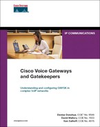
Because the IPIPGW terminates and reoriginates the signaling call leg, the DTMF relay tones need to be transmitted across the 2 call legs. Based on the configuration, you can send a similar DTMF type across the outbound VoIP type or, in certain cases, you can change the DTMF type from one type to another, as shown in Table 18-1.
Table 18-1. DTMF Types Supported on the IPIPGW
For example, you can transmit H.245 alphanumeric as the same H.245 alphanumeric DTMF, or you can convert the H.245 alphanumeric on the H.323 call leg to SIP RFC 2833, or SIP NOTIFY on the SIP call leg, and vice versa. For DTMF types such as RFC 2833, the media must flow through the IPIPGW.
Admission Confirm (ACF)/Location Confirm (LCF) DTMF Relay is configured under the VoIP dial peer configuration mode. It needs to be configured under both the incoming as well as the outgoing VoIP dial peer. The command syntax is dtmf-relay cisco-rtp|h245-alphanumeric|h245-signal|rtp-nte|sip-notify. Example 18-7 illustrates the configuration commands for implementing RFC 2833 dtmf type.
Example 18-7. Configuring RFC 2833 DTMF
IP-to-IP_GW(config)#dial-peer voice 1 voip
IP-to-IP_GW(config-dial-peer)#dtmf-relay rtp-nte
Fax Support
A fax call is treated similarly to a voice call. Standards-based T.38 and other fax types such as Cisco fax relay and fax pass-through are supported. Interworking between H.323 and SIP fax calls is also supported. When you configure fax, you can use the regular fax commands either globally or under the specific inbound and outbound VoIP dial peers. Interworking between various fax types is not possible. For example, you cannot convert a T.38 fax call to a fax pass-through call.
Quality of Service
The Cisco Multiservice IPIPGW supports all the QoS features that are available in Cisco IOS. Features such as low-latency queuing (LLQ), IP precedence, and DSCP are supported on the gateway. You could remark the signaling, in addition to media packets, appropriately before sending the traffic into the network. By applying the right QoS policies, you can provide better service to selected traffic. You can use the regular Cisco IOS commands for QoS for configuration.
Call Admission Control
CAC is a deterministic and informed decision made before you establish a voice or video call. CAC is based on whether the required network resources are available to provide suitable QoS for the new call. Different CAC mechanisms are supported on the Cisco Multiservice IPIPGW and, based on the need and network design of the specific customers, you could apply one of the following mechanisms.
RSVP-Based CAC
Cisco IPIPGW uses RSVP to limit the accepted voice or video load on the IP network to guarantee the QoS levels of calls. The Cisco IPIPGW CAC that is using RSVP synchronizes RSVP signaling with the protocol (H.323 or SIP) signaling to ensure that the bandwidth reservation is established in both directions before a call moves to the alerting phase (ringing). This ensures that the called party phone rings only after you have reserved the resources for the call. With RSVP-based admission control, the IPIPGW can reserve network bandwidth and react appropriately if bandwidth reservation fails.
Max Connections-Based CAC
The maximum connections CAC mechanism involves using the max-conn VoIP dial-peer configuration command on a dial peer of the outgoing leg to restrict the number of concurrent connections (calls) that can be active on that dial peer at any one time.
IP Call Capacity-Based CAC
CAC can also be provided based on carrier ID. Carrier ID is an attribute that consists of up to 127 alphanumeric characters that identify the carrier that is handling H.323 calls. This CAC mechanism works in conjunction with a Cisco gatekeeper. You can match incoming calls that have a certain carrier ID configured. Only the configured maximum capacity of calls is allowed to traverse the IPIPGW.
You configure the IP circuit under the voice service voip and h323 configuration mode. The command syntax is ip circuit carrier-id carrier name reserved-calls reserved. The carrier name defines an IP circuit using the specified name as the circuit ID, and the reserved keyword defines the maximum number of calls for the circuit ID. Example 18-8 illustrates the configuration commands for ip circuit. max-calls sets the number of maximum aggregate H.323 IP circuit carrier call legs. The reserved-calls number has to be double the number of calls allowed to pass the IPIPGW. Therefore, in Example 18-8, 200 calls would be allowed through the gateway for carrier XYZ. Also, more than one carrier ID can be configured.
Example 18-8. Configuring CAC Based on IP Circuits
IPIPGateway#config t
IPIPGateway(config)#voice service voip
IP-to-IP_GW(conf-voi-serv)#h323
IP-to-IP_GW(conf-serv-h323)#ip circuit max-calls 800
IP-to-IP_GW(conf-serv-h323)#ip circuit carrier-id XYZ reserved-calls 400
Thresholds Based on CPU, Memory, and Total Calls
It is critical to configure the gateway so that it accepts calls based on certain resources. If the resources are being highly used or are falling below configured limits, you should reject the incoming calls with a configured type of treatment. You can configure call treatment to send a certain type of a cause code so that the originating gateway can reroute the call to the next available gateway. You can provision CAC based on monitoring certain resources of the IPIPGW, such as these:
• CPU
• Memory
• Total number of calls
You can configure the IPIPGW to handle VoIP based on the minimum and maximum limits that are configured. Based on the resource that is monitored, you could apply appropriate treatment when the resource reaches the configured low or high threshold window mark.
You configure CAC based on CPU, memory, and total calls in the global configuration mode.
The command syntax for configuring call threshold based on CPU utilization for the last 5 seconds is call threshold global cpu-5sec low low-threshold high high-threshold. Example 18-9 illustrates the configuration commands for setting a CPU low threshold of 5 percent and a high threshold of 90 percent measured in the last 5 seconds.
Example 18-9. Configuring CAC Control Based on CPU
IPIPGateway(config)#call threshold global cpu-5sec low 5 high 90
The command syntax for configuring call threshold based on average CPU utilization is call threshold global cpu-avg low low-threshold high high-threshold. Example 18-10 illustrates the configuration commands for configuring thresholds of the average CPU utilization for 5 percent (low) or 75 percent (high).
Example 18-10. Configuring CAC Based on CPU
IPIPGateway(config)#call threshold global cpu-avg low 5 high 75
The command syntax for configuring call threshold based on average CPU utilization is call threshold global total-mem low low-threshold high high-threshold. Example 18-11 illustrates the configuration commands for enabling CAC based on memory. The low threshold is set to 10 percent, and the high threshold is set to 75 percent of the gateway memory.
Example 18-11. Configuring CAC Based on Memory
IPIPGateway(config)#call threshold global total-mem low 10 high 75
The command syntax for configuring call threshold based on total number of calls that the IPIPGW would handle is call threshold global total-calls low low-threshold high high-threshold. Example 18-12 illustrates the configuration commands for enabling CAC based on the total number of calls to be handled. The low threshold is set to 1 call, and the high threshold is set to 800 calls.
Example 18-12. Configuring CAC Based on Total Calls
IPIPGateway(config)#call threshold global total-calls low 1 high 800
You need to turn on call treatment to take the appropriate action when the gateway resources hit the low or the high threshold mark. You can also configure call treatment so that a particular cause code is returned. The command syntax for enabling call treatment is call threshold on. Example 18-13 illustrates the configuration commands for enabling call treatment. Various options of what cause code could be sent are shown in the call treatment cause-code command.
Example 18-13. Configuring Call Treatment
IPIPGatewayconfig)#call treatment on
IPIPGateway(config)#call treatment cause-code ?
busy Insert cause code indicating the GW is busy (17)
no-QoS Insert cause code indicating the GW can't provide QOS (49)
no-resource Insert cause code indicating the GW has no resource (47)
Transcoding
Transcoding functionality is supported on the IPIPGW routers. Using transcoding services reduces bandwidth on the WAN side, resulting in tangible cost savings. DSP farms provide the transcoding services using DSP resources that are installed either on the router motherboard or on high-density digital voice/fax network modules. The transcoding functionality is supported between G.711 and G.729 codecs. Table 18-2 lists the variants and packetizations.

Note
Only 2800s, 2600XMs, 2691, 3700s, and 3800s support transcoding.
You can use the DSP farm that is used for the transcoding on the same router platform as the IPIPGW or on an external router.
IPIPGW uses the Skinny server to talk to the DSP farm. When you enable transcoding on the IPIPGW, you use the same configuration commands that you used in the Cisco CallManager Express (CME).
VXML and Tcl Scripts
You can run voice XML and Toolkit Command Language (Tcl) scripts on the IPIPGW. DSPs are not required for use of this feature. You have to record prompts in the same codec type that you use for the call. For example, you should use prompts that are recorded in G711μlaw for G711μlaw calls. The scripts are applied to the VoIP dial peer. Because of the rich set of DTMF types that are supported (for example, H.245 alphanumeric, H.245 signal, SIP RFC 2833, and SIP NOTIFY), this is a useful feature for many customers who are deploying services, such as prepaid calling cards.
Billing
You can collect call detail records (CDRs) on the IPIPGW, similar to the way you collect them on a regular Cisco IOS TDM gateway. The CDRs are generated for both legs of the call, regardless of whether it is an H.323 or a SIP call. Conference ID is the common field, which you can use to corelate the two call legs for the voice call. Capability for gathering voice quality statistics based on packet loss, jitter, and round trip time is available.
show Commands
You can use many of the show commands that are employed on the Cisco voice gateways on the IPIPGW. Each voice call that passes through the IPIPGW has two VoIP media streams in the media flow-through. Example 18-14 illustrates the show command for checking the two VoIP media streams on the IPIPGW in the media flow-through mode. The command output displays the active RTP connections and the call identifiers for each leg of the VoIP. Connection 1, which is call identifier 31, signifies the connection between the IPIPGW and the originating endpoint. Connection 2 (Call ID 32) signifies the second call leg, which is the connection between the IPIPGW and the terminating endpoint. The User Datagram Protocol (UDP) ports are shown for the local (IPIPGW) and remote endpoints (originating and terminating endpoints). The LocalIP is the IP address of the IPIPGW, and the RemoteIP is the IP address of the originating and terminating endpoint.
Example 18-14. Displaying Media Streams
IP-to-IP_GW#show voip rtp connections
VoIP RTP active connections :
No. CallId dstCallId LocalRTP RmtRTP LocalIP RemoteIP
1 31 32 17612 17978 200.1.1.3 60.60.60.75
2 32 31 18164 29128 200.1.1.3 200.1.1.75
Found 2 active RTP connections
debug Commands
The following debug commands are helpful for troubleshooting IPIPGW call flows. Based on the protocols that you are using, you can turn on the appropriate debugs to diagnose the problem.
• H.323–H.323 scenarios:
—debug h225 asn1
—debug h225 events
—debug h245 asn1
—debug h245 events
—debug h225 q931
—debug cch323 all
—debug gatekeeper main 10
—debug voip ipipgw
—debug voip ccapi inout
• H.323–SIP scenarios:
—debug h225 asn1
—debug h225 events
—debug h245 events
—debug cch323 all
—debug voip ipipgw
—debug voip ccapi inout
—debug ccsip all
• SIP-SIP scenarios:
—debug ccsip all
—debug voip ccapi inout
• RSVP scenarios:
—debug call rsvp-sync events
—debug call rsvp-sync func-trace
Case Study: Providing Enterprise VoIP Trunking to VoIP Service of the Service Provider
The New York office needs to connect a CallManager H.225 trunk to a SIP service provider. The CallManager is version 4.1.3. To provide security and protocol interworking, you plan to implement an IPIPGW to connect with the service provider, as shown in Figure 18-6.
Figure 18-6. New York IPIPGW Implementation
CallManager Configuration
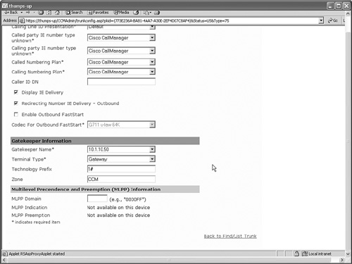
Note the following points in CallManager trunk configuration:
• Configure the CallManager with an H.225 gatekeeper-controlled trunk
• Check Media Termination Point Required
• Uncheck Wait for Far End H.245 Terminal Capability Set
• Check Enable Inbound FastStart
• Gatekeeper Name should be IP Address Gatekeeper
• Gatekeeper Terminal Type should be Gateway
• Technology prefix should be 1#
Example 18-15 shows the configuration steps for implementing the IPIPGW. In this example, the Cisco IOS gatekeeper and the IPIPGW are running on the same router platform.
Example 18-15. IPIPGW Implementation
!
! Enabling IPIPGW functionality
!
IPIPGateway#config t
IPIPGateway(config)#voice service voip
IPIPGateway(conf-voi-serv)#allow-connections h323 to sip
IPIPGateway(conf-voi-serv)#allow-connections sip to h323
IPIPGateway(config-voi-serv)#exit
!
! Configuring the gatekeeper
!
IPIPGateway(config)#gatekeeper
IPIPGateway(config-gk)#zone local via_gk zone2
IPIPGateway(config-gk)#zone local CCM zone2 invia via_gk outvia via_gk
IPIPGateway(config-gk)#zone prefix CCM 2125553... gw-priority 6 IPIPGatewayTrunk_1
IPIPGateway(config-gk)#gw-type-prefix 1#* default-technology
IPIPGateway(config-gk)#no shutdown
IPIPGateway(config-gk)#exit
!
! Configuring the H.323 gateway to register with the gatekeeper
!
IPIPGateway(config)#interface GigabitEthernet0/0
IPIPGateway(config-if)#ip address 10.1.10.50 255.255.255.0
IPIPGateway(config-if)#h323-gateway voip interface
IPIPGateway(config-if)#h323-gateway voip id via_gk ipaddr 10.1.10.50 1719
IPIPGateway(config-if)#h323-gateway voip h323-id IP-to-IP_GW
IPIPGateway(config-if)#exit
!
! Configuring SIP user-agent section to point toward the service provider SIP proxy
!
IPIPGateway(config)#sip-ua
IPIPGateway(config-sip-ua)#authentication username ipip password 01100F175804 realm
CISCO
IPIPGateway(config-sip-ua)#sip-server dns:csps-release.gb.com
IPIPGateway(config-sip-ua)#exit
!
! Configuring the VoIP dial peers for routing calls from and to the Cisco CallManager
!
IPIPGateway(config)#dial-peer voice 1 voip
IPIPGateway(config-dial-peer)#destination-pattern 4088536...
IPIPGateway(config-dial-peer)#session protocol sipv2
IPIPGateway(config-dial-peer)#session target sip-server
IPIPGateway(config-dial-peer)#codec g711ulaw
IPIPGateway(config-dial-peer)#exit
!
IPIPGateway(config)#dial-peer voice 2 voip
IPIPGateway(config-dial-peer)#destination-pattern 2125553...
IPIPGateway(config-dial-peer)#session target ras
IPIPGateway(config-dial-peer)#incoming called-number .T
IPIPGateway(config-dial-peer)#codec g711ulaw
IPIPGateway(config-dial-peer)#end
Figures 18-7, 18-8, and 18-9 illustrate the CallManager H.225 trunk configuration.
Figure 18-7. CallManager H.225 Trunk Configuration

Figure 18-8. CallManager H.225 Trunk Configuration
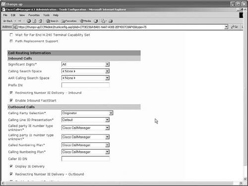
Figure 18-9. CallManager H.225 Trunk Configuration
Review Questions
1 Why would you use media flow-around?
2 What is needed to implement an IPIPGW?
3 What is a via-zone?
4 Under what circumstances is a DSP needed in an IPIPGW call?
5 What platforms are supported for the Cisco Multiservice IPIPGW?
6 Can the Cisco Multiservice IPIPGW register to more than one gatekeeper?
7 Can you use the Cisco Multiservice IPIPGW without a gatekeeper?
8 Are translation rules and digit manipulation supported on the Cisco Multiservice IPIPGW?