Chapter 8. Connecting to an IP WAN
The previous chapters have focused on Voice over IP (VoIP) within the IP network at a single site. The gateway in such a setup would interconnect public switched telephone network (PSTN), PBX, and other plain old telephone service (POTS) endpoints with voice-enabled IP endpoints, such as IP phones. VoIP over the WAN has several applications, such as connecting multiple sites, allowing service providers to terminate long-distance and local voice calls, providing voice services to telecommuters, and so on.
In this chapter you will learn
• Applications for connecting to an IP WAN
• Design considerations when using VoIP over an IP WAN
• Quality of Service issues and solutions
• Configuring Quality of Service to fit a provider’s MPLS standards
• Providing fax and modem services within a VoIP network
• Ways to secure your VoIP traffic
Applications for Connecting to an IP WAN
Connecting voice gateways over an IP WAN allows you to send voice and video to other locations as IP packets. For businesses that have geographically distributed offices, using IP telephony to call between offices can be more cost effective than making long-distance calls. IP telephony is increasingly becoming a need for businesses that spread their offices globally. It lets you leverage your investment in WAN bandwidth between offices. The WAN connection can be a direct circuit between sites, such as a T1; a virtual circuit, including Frame Relay; ATM permanent virtual circuit (PVC); or a shared connection, as with a Synchronous Optical Network (SONET) ring. Communication between the voice gateways could rely on your service provider, such as with Multiprotocol Label Switching (MPLS), or on the Internet, as when using a virtual private network (VPN) between sites. Satellite links are also an option, provided their speed and reliability are acceptable.
The following are some situations in which IP WAN connections might be appropriate:
• Your company is using VoIP at multiple sites. Sending voice over the WAN connections between them is a way to make intracompany phone calls without using the PSTN. Voice performance is better with a full-mesh topology. In a hub-and-spoke design, spoke-to-spoke phone calls have to go through the hub, adding extra delay to the call. Careful attention to quality of service (QoS) is essential when sending Voice over Frame Relay (VoFR) or Voice over ATM (VoATM). PPP has no built-in QoS mechanisms; therefore, it needs multilevel precedence and preemption (MLPP) to be deployed to ensure that latency and delay requirements for voice are met.
• You want to do “tail end hop-off,” which turns a long-distance call into a local one. (In tail end hop-off, you route voice traffic that is bound for a phone in a particular area to your voice gateway in that area. The voice gateway then routes the traffic out to the PSTN as a local call.)
• A company that wants to preserve its PBX investment yet avoid the cost of POTS lines and trunks can take advantage of existing WAN links for voice between sites. In this case, the voice gateway translates between the internal analog voice and the external VoIP. You need to create dial peers that point to the PBX and to the other voice gateways.
• Companies might want to centralize their PSTN connections and require remote sites to route all voice traffic bound to the PSTN through a central site. The central site needs enough PRI connections to handle the calls, and each remote site needs only minimal POTS lines in case the WAN connection is lost or for emergency calls. This centralization is normally done when all the sites are located in the same area.
• Centralizing Cisco CallManagers reduces the financial investment in IP telephony. In a centralized design, Cisco CallManagers communicate with the other voice devices over an IP WAN. Signaling between phones and CallManagers, and between gateways and CallManagers, is sent over the WAN. Voice media traffic flows directly between the IP phones and the gateway at the remote site and might not traverse the WAN.
Design Considerations
In most scenarios, voice and data are sent together on the same WAN connection. Sending voice along with data over a WAN network requires additional planning and configuration. This book focuses on gateways, but you must plan for voice flow throughout your network and configure every network device appropriately.
Be sure to consider the following areas when designing a voice-enabled WAN:
• Bandwidth—Estimate the number of calls you anticipate over the WAN, plus the amount of data traffic, and ensure that you have enough bandwidth. For more information on bandwidth planning, see Chapter 16, “Deploying Gatekeepers.”
• Call admission control (CAC)—If the gateway sends out more calls than the WAN can handle, the quality of all calls suffers. Chapter 11, “Influencing Path Selection,” covers CAC.
• QoS—If voice will share the WAN link with data, you should protect voice (and video) from data. The next section of this chapter covers QoS.
• Security—Consider how secure your network must be and what devices the voice traffic will traverse. For more information on security, see the “Security” section later in this chapter.
Quality of Service
Typically, data and voice traffic travel across the same WAN link. This can be a problem, because data tends to be transmitted in bursts and could use up all the bandwidth, leaving none for voice. QoS techniques help protect voice (and video) from data.
Planning is the most important part of QoS. In most networks, it is not enough to classify traffic as “voice” and “nonvoice” and give preference to voice. Most networks have various types of traffic, each with its own network needs and importance to the company. Although this book concentrates on voice, an effective QoS policy examines all the network applications and involves policy makers in deciding how to handle that data through the network. Your goal should be a consistent, end-to-end QoS strategy throughout your company.
One of your first tasks is to determine the needs of each network application. Voice is sensitive to delay, jitter, and drops. High-quality voice and interactive video have the following recommendations:
• A maximum of 150 ms of one-way delay
• A maximum of 30 ms of jitter
• A maximum of 1 percent packet loss
One cause of delay is small voice packets having to wait behind larger data packets to be sent out an interface. Jitter, which is variable delay, can result when some voice packets are sent out quickly and some have to wait. Drops happen when an interface queue is completely full—something much more likely to occur if voice has to share a queue with data. Thus, when you are sending voice and data across a WAN it is especially important to plan and implement QoS measures to increase the chances of voice always having the bandwidth it needs.
• Classifying traffic
• Marking the classified traffic
• Configuring network devices to treat traffic differently based on the markings
The modular quality of service command-line interface (MQC) is the recommended method of implementing QoS. It involves using class maps to classify traffic, using policy maps to mark traffic or specify how it will be treated, and applying the policy using the service-policy command. In the following sections, you will look at using MQC with voice gateways.
Note
A full explanation of QoS is beyond the scope of this book. You can find detailed information in the Cisco QoS Solution Reference Network Design document at http://www.cisco.com/go/srnd, or in these books:
• Cisco Catalyst QOS:Quality of Service in Campus Networks by Michael Flannagan, Richard Froom, and Kevin Turek
• End-to-End QoS Network Design:Quality of Service in LANs, WANs, and VPNs by Christina Hattinghand and Tim Szigeti
Using Class Maps to Classify Traffic
Classifying traffic requires looking at it and identifying it according to some characteristic, such as port number or source address. After you classify traffic, you can configure routers and switches to treat it differently from other traffic. The MQC uses class maps to classify traffic. Classification can be based on many different things, but voice is typically identified by looking in the OSI Layer 4, Layer 3, or Layer 2 packet headers.
Classifying at Layer 4
You can classify traffic based on the port number in the TCP or User Datagram Protocol (UDP) packet header. Each voice application uses specific port numbers. Table 8-1 lists the default port numbers that common voice-related protocols use.
Table 8-1. Voice Protocols and Port Numbers

You can use either an access list or a class map to identify this traffic based on the port number. Example 8-1 shows how to do this with an access list. The access list is created and then referenced in a class map. This example classifies the SCCP signaling traffic separately from the voice RTP traffic.
Example 8-1. Configuring Access Lists and Class Maps
VGateway#conf t
VGateway(config)#ip access-list extended RTP
VGateway(config-ext-nacl)#permit udp any any range 16383 32767
!
VGateway(config-ext-nacl)#ip access-list extended SCCP
VGateway(config-ext-nacl)#permit tcp any any range 2000 2002
VGateway(config-ext-nacl)#exit
!
VGateway(config)#class-map match-all VOICE
VGateway(configs-cmap)#match access-group name RTP
!
VGateway(configs-cmap)#class-map match-all SIGNALING
VGateway(configs-cmap)#match access-group name SCCP
This configuration gives you two class maps that break out two types of traffic, as verified in Example 8-2. The class map VOICE identifies the RTP traffic that is permitted in access list RTP, and the class map SIGNALING identifies the SCCP traffic that is permitted in access list SCCP. What about the rest of the data traveling around the network? A default class exists, and anything that is not explicitly identified falls into that, as shown in Example 8-2.
Example 8-2. Verifying Class Map Configuration
VGateway#show class-map
Class Map match-any class-default (id 0)
Match any
Class Map match-all VOICE (id 2)
Match access-group name RTP
Class Map match-all SIGNALING (id 3)
Match access-group name SCCP
Example 8-3 shows a class map that matches RTP traffic directly. Using a class map in this way lets you bypass configuring an access list for RTP. However, you need to beware of two pitfalls in this technique.
First, using a class map this way matches only the even ports in the range you specify. RTP bearer traffic uses the even ports, and control traffic uses the odd ports. Therefore, matching against RTP in a class map breaks out only the voice-bearer traffic, not the control traffic.
Second, the way you specify the range of ports is not intuitive. In the access list shown in Example 8-1, the starting and ending port numbers are listed. In a class map, the starting port is specified, but the second number is not the ending port number. The second number is what you would add to the first number to get the ending port. For instance, suppose that you wanted to start at port 16383 and match the next 2000 ports. In that case, you would give the match ip rtp 16383 2000 command. That would match ports 16383 through 18383 (16383 plus 2000). In Example 8-3, class map Voice-Bearer matches the even ports in the range 16383 through 32766 (16383 plus 16383.) Notice that no option is available to match SCCP, MGCP, H.323, or SIP.
Example 8-3. Using a Class Map to Identify RTP Traffic
VGateway(config)#class-map Voice-Bearer
VGateway(config-cmap)#match?
access-group Access group
any Any packets
class-map Class map
cos IEEE 802.1Q/ISL class of service/user priority values
destination-address Destination address
fr-de Match on Frame-relay DE bit
input-interface Select an input interface to match
ip IP specific values
mpls Multi Protocol Label Switching specific values
not Negate this match result
protocol Protocol
qos-group Qos-group
source-address Source address
VGateway(config-cmap)#match ip ?
dscp Match IP DSCP (DiffServ CodePoints)
precedence Match IP precedence
rtp Match RTP port nos
VGateway(config-cmap)#match ip rtp 16383 16383
!
VGateway(config-cmap)#do show class-map
Class Map match-any class-default (id 0)
Match any
Class Map match-all Voice-Bearer (id 2)
Match ip rtp 16383 16383
Classifying at Layer 3
A second way to identify traffic is to look at the Type of Service (ToS) field in the Layer 3 IP header. The first six bits of this field are called the differentiated services code point (DSCP) bits. They are typically set to a decimal value of 46 for voice-bearer traffic. In the past, Cisco recommended setting voice signaling traffic to DSCP 31. However, the current recommendation is to set it to Class Selector (CS)3. You can use an access list to identify traffic with a certain DSCP value, or match against it in a class map. Example 8-4 shows an access list that looks at the DSCP value in packets. As you can see from the example, you can list the DSCP either as a decimal value or its DiffServ per-hop behavior (PHB) value. The second access list, VOICE-SIG, permits both CS3 and Assured Forwarding (AF)31 to allow for devices that might not yet be transitioned to using only CS3 for signaling. After you create the access lists, you associate them with class maps.
Example 8-4. Using an Access List to Match DSCP
VGateway(config)#ip access-list extended VOICE-BRR
VGateway(config-ext-nacl)#permit ip any any dscp ?
<0-63> Differentiated services codepoint value
af11 Match packets with AF11 dscp (001010)
af12 Match packets with AF12 dscp (001100)
af13 Match packets with AF13 dscp (001110)
af21 Match packets with AF21 dscp (010010)
af22 Match packets with AF22 dscp (010100)
af23 Match packets with AF23 dscp (010110)
af31 Match packets with AF31 dscp (011010)
af32 Match packets with AF32 dscp (011100)
af33 Match packets with AF33 dscp (011110)
af41 Match packets with AF41 dscp (100010)
af42 Match packets with AF42 dscp (100100)
af43 Match packets with AF43 dscp (100110)
cs1 Match packets with CS1(precedence 1) dscp (001000)
cs2 Match packets with CS2(precedence 2) dscp (010000)
cs3 Match packets with CS3(precedence 3) dscp (011000)
cs4 Match packets with CS4(precedence 4) dscp (100000)
cs5 Match packets with CS5(precedence 5) dscp (101000)
cs6 Match packets with CS6(precedence 6) dscp (110000)
cs7 Match packets with CS7(precedence 7) dscp (111000)
default Match packets with default dscp (000000)
ef Match packets with EF dscp (101110)
VGateway(config-ext-nacl)#permit ip any any dscp ef
!
VGateway(config-ext-nacl)#ip access-list extended VOICE-SIG
VGateway(config-ext-nacl)#permit ip any any dscp cs3
VGateway(config-ext-nacl)#permit ip any any dscp af31
Using a class map to identify traffic based on a DSCP value is shown in Example 8-5. Notice in the output of the show class-map command that, although you specified the decimal DSCP value when configuring the class map, the router has translated that to its Diffserv value of expedited forwarding (EF). The number in parenthesis in Example 8-5 is the decimal value.
Example 8-5. Using a Class Map to Match DSCP
VGateway(config)#class-map DSCP_46
VGateway(config-cmap)#match dscp 46
!
VGateway(config-cmap)#class-map CS3
VGateway(config-cmap)#match ip dscp cs3
!
VGateway#show class-map
Class Map match-all CS3 (id 6)
Match ip dscp cs1 (8)
Class Map match-all DSCP_46 (id 5)
Match dscp ef (46)
Classifying at Layer 2
A third way to identify traffic is by looking at the 802.1Q trunking tag or ISL trunking header. There are three bits called the class of service (COS), which are bits that you can set to identify different types of traffic. These bits are usually set to a decimal value of 5 for voice. You can match these bits in a class map. Of course, this only works if the router has an interface that is performing Ethernet trunking. Example 8-6 shows a class map that identifies traffic at Layer 2 by the CoS value.
Example 8-6. Using a Class Map to Match CoS
VGateway(config)#class-map COS-Voice
VGateway(config-cmap)#match cos ?
<0-7> Enter up to 4 class-of-service values separated by white-spaces
VGateway(config-cmap)#match cos 5
!
VGateway#show class-map
Class Map match-all COS-Voice (id 4)
Match cos 5
Cisco IP phones place an 802.1 tag on the voice traffic they send. The CoS is set to 5 for voice-bearer traffic and 3 for voice-signaling traffic. Any traffic from a PC that is connected to the phone is sent untagged. QoS should be enabled on the directly connected switch, and the switch interface should be set to trust the Cisco phone. When this happens, the switch looks at the CoS value before it removes the Layer 2 header, and it translates it into a DSCP value as the packet moves through the switch. Untagged PC traffic gets a DSCP value of 0 by default. When the packet is sent out a switch interface, it is marked at Layer 3 with that DSCP value. (It might also have a CoS value if the outgoing interface is a trunk interface.) Configure the switch to put the desired DSCP value on any packets that you want marked. Their Layer 2 header changes as they move through the network, but you can match against that unchanging Layer 3 DSCP value.
Using Policy Maps
After you have identified the interesting traffic, you can mark it or set policies for it. Marking traffic involves setting the DSCP bits or the CoS bits. You should classify and mark traffic as close to the end devices as possible, because classifying traffic uses router and switch resources. This is most important for routers, which perform QoS in software. Imagine if every router and switch in the network had to look into every packet to examine its port number. It is much more efficient if the first switch that a packet touches does the classifying and then sets a DSCP value based on the type of traffic it is. Then every other switch and router in the network can trust that the marking is correct and treat the traffic accordingly. This creates a trust boundary at the access switch.
The MQC applies policies to the traffic that has been classified by using a policy map. A policy map references the previously created class maps and then specifies what is to be done with traffic in each class. The traffic could, for example, be marked, allocated a minimum bandwidth, limited to a maximum bandwidth, prioritized, or even dropped altogether. You apply policy maps to interfaces. A separate queue is created at the interface for each class map, and the traffic that is identified by each class map is placed in its queue. This allows you to treat each of the classes of traffic differently.
Example 8-7 shows an example of marking traffic in a policy map. The class map CoS-Voice was created in Example 8-6. It identifies traffic with a CoS value of 5 in the 802.1Q trunking tag. This example creates a policy map that marks all the traffic classified by CoS-Voice with a DSCP value of 46 (or EF).
Example 8-7. Marking Traffic Using a Policy Map
VGateway(config)#policy-map COS-TO-DSCP
VGateway(config-pmap)#class COS-Voice
VGateway(config-pmap-c)#set dscp 46
!
VGateway(config-pmap-c)#class class-default
VGateway(config-pmap-c)#set dscp 0
!
VGateway#show policy-map
Policy Map COS-TO-DSCP
Class COS-Voice
set dscp ef
Class class-default
set dscp default
Notice that in Example 8-7, all traffic other than that marked with a CoS of 5 is set to a DSCP of 0 under the default class. If you have routing traffic, it is a good idea to break that out separately before classifying everything else as DSCP 0. Notice also that even though the policy map was configured using decimal values, when you display it, those are translated to the PHB values.
You most commonly use a policy map to specify different treatment for the traffic in each queue created by a class map. Setting policy and marking traffic are not mutually exclusive—you can do both of them to the same class. Voice is typically placed in a priority queue, called a low-latency queue (LLQ). It is important to understand that this is a strict priority queue. If any traffic is in the queue, it is sent out before other traffic. You can limit the amount of bandwidth used by the priority queue, however, so that other traffic is not starved.
How much bandwidth should you allow in the priority queue? In planning your bandwidth requirements, take into account the anticipated data load plus the voice load. The amount of bandwidth allocated per call varies depending on the coding/decoding (codec) used. Codec describes methods of compressing voice. The most typically used are G.711, which is uncompressed voice, and G.729, which is a type of compressed voice. G.711 is usually used in the LAN where bandwidth is plentiful. G.729 is typically used in the WAN, where you have lower bandwidth links. A G.711 call, sent at 64 kbps, has a payload size of 160 bytes. A G.729 call, sent at 8 kbps, uses a payload size of 20 bytes.
IP, UDP, and RTP headers are put onto each packet. The IP header is 20 bytes, UDP is 8 bytes, and RTP is 12 bytes, totaling an additional 40 bytes for each VoIP packet. You have the option of compressing the IP, UDP, and RTP headers, which reduces the header overhead to 2 to 4 bytes, thus reducing the entire packet size and using less bandwidth. For more information on compression, see the “Compression” section later in this chapter.
When you are planning bandwidth allocation, also take into consideration the Layer 2 headers to be used. For instance, Ethernet adds an 18-byte header, whereas Frame Relay adds only 6 bytes. Multilink PPP also has a 6-byte header. The ATM header is 5 bytes. If you use MPLS in your WAN network, the MPLS edge router adds a 4-byte header. If you are sending voice over the Internet, you might want to encrypt it in an IPsec tunnel for added security. IPsec adds 50 to 57 bytes of overhead. Secure Real-Time Transport Protocol (SRTP) encrypts the payload of IP voice packets and adds 4 bytes to the packet.
As a general rule, 21 to 320 kbps of bandwidth is required per call, depending on the codec and overhead. A good recommendation when running voice and data through the same interface is to limit the LLQ to about one-third of the bandwidth. This usually allows enough remaining bandwidth to divide between the data classes.
IP video conferencing (IP/VC) adds additional considerations to your QoS design. Interactive video has the same network needs as voice—150 ms maximum delay, jitter of 30 ms or less, and loss of 1 percent or less—so it is frequently put in a LLQ. However, video traffic varies widely in packet sizes and transmission rates. A typical video conferencing stream averages 384 kpbs of bandwidth. Cisco recommends overprovisioning the bandwidth by 20 percent, bringing it to 460 kbps per IP/VC stream. LLQ allows bursts of up to 200 ms, which is usually enough for one video stream. If you will be sending multiple streams through an interface, you might need to adjust the burst size. You can specify the burst parameter when you create the LLQ in the policy map, as part of the priority command, as shown in Example 8-8. No hard and fast rule is available about how much to increase the burst parameter. You need to test as multiple IP/VC streams are added.
In Example 8-8, classes are created for voice, video conferencing, and call signaling. These classes are allotted bandwidth in the policy map. Voice and video are put into the LLQ, and the burst value for video is changed. Keep in mind that this is a simplistic example. In your network, you will most likely have other traffic that should be classified and included in the policy map.
Example 8-8. Policy Map for Voice and Video Traffic
VGateway(config)#class-map Voice
VGateway(config-cmap)#match dscp ef
!
VGateway(config-cmap)#class-map Video
VGateway(config-cmap)#match dscp 41
!
VGateway(config)#class-map match-any Call_Signaling
VGateway(config-cmap)#match dscp cs3
VGateway(config-cmap)#match dscp af31
!
VGateway(config-cmap)#policy-map VOICE-VIDEO
VGateway(config-pmap)#class Voice
VGateway(config-pmap-c)#priority percent 15
!
VGateway(config-pmap-c)#class Video
VGateway(config-pmap-c)#priority percent 18 ?
<32-2000000> Burst in bytes
<cr>
VGateway(config-pmap-c)#priority percent 18 30000
!
VGateway(config-pmap-c)#class Call_Signaling
VGateway(config-pmap-c)#bandwidth percent 5
!
VGateway(config-pmap-c)#class class-default
VGateway(config-pmap-c)#fair-queue
VGateway(config-pmap-c)#random-detect dscp-based
!
VGateway(config-pmap-c)#int s0/0
VGateway(config-if)#service-policy output VOICE-VIDEO
Notice the fair-queue and random-detect dscp-based commands under the class-default. The fair-queue command tells the router to create a separate queue for each conversation, or traffic flow, that falls into the default class. The random-detect command enables weighted random early detection (WRED) within that class. It tells the router to drop random packets from flows as the queue begins to fill up. This is done in an attempt to prevent the queue from filling completely and dropping all new packets. When the dscp-based command is added, the router drops packets based on their DSCP value. Packets with higher DSCP values are dropped later than lower valued ones.
The policy is applied to interface serial 0/0 and affects outbound traffic. An extremely useful command to verify and monitor your QoS configuration is show policy interface interface_number. Example 8-9 shows the output from this command. Although the router currently has no traffic, you can see that the command gives a detailed picture of the policy and its effect on traffic through that interface.
Example 8-9. show policy interface Command Output
VGateway#show policy interface s0/0
Serial0/0
Service-policy output: VOICE-VIDEO
Class-map: Voice (match-all)
0 packets, 0 bytes
5 minute offered rate 0 bps, drop rate 0 bps
Match: dscp ef (46)
Queueing
Strict Priority
Output Queue: Conversation 264
Bandwidth 15 (%)
Bandwidth 450 (kbps) Burst 11250 (Bytes)
(pkts matched/bytes matched) 0/0
(total drops/bytes drops) 0/0
Class-map: Video (match-all)
0 packets, 0 bytes
5 minute offered rate 0 bps, drop rate 0 bps
Match: dscp 41
Queueing
Strict Priority
Output Queue: Conversation 264
Bandwidth 18 (%)
Bandwidth 540 (kbps) Burst 30000 (Bytes)
(pkts matched/bytes matched) 0/0
(total drops/bytes drops) 0/0
Class-map: Call_Signaling (match-any)
0 packets, 0 bytes
5 minute offered rate 0 bps, drop rate 0 bps
Match: dscp cs3 (24)
0 packets, 0 bytes
5 minute rate 0 bps
Match: dscp af31 (26)
0 packets, 0 bytes
5 minute rate 0 bps
Queueing
Output Queue: Conversation 265
Bandwidth 5 (%)
Bandwidth 150 (kbps) Max Threshold 64 (packets)
(pkts matched/bytes matched) 0/0
(depth/total drops/no-buffer drops) 0/0/0
Class-map: class-default (match-any)
0 packets, 0 bytes
5 minute offered rate 0 bps, drop rate 0 bps
Match: any
Queueing
Flow Based Fair Queueing
Maximum Number of Hashed Queues 256
(total queued/total drops/no-buffer drops) 0/0/0
exponential weight: 9
dscp Transmitted Random drop Tail drop Minimum Maximum Mark
pkts/bytes pkts/bytes pkts/bytes thresh thresh prob
af11 0/0 0/0 0/0 32 40 1/10
af12 0/0 0/0 0/0 28 40 1/10
af13 0/0 0/0 0/0 24 40 1/10
af21 0/0 0/0 0/0 32 40 1/10
af22 0/0 0/0 0/0 28 40 1/10
af23 0/0 0/0 0/0 24 40 1/10
af31 0/0 0/0 0/0 32 40 1/10
af32 0/0 0/0 0/0 28 40 1/10
af33 0/0 0/0 0/0 24 40 1/10
af41 0/0 0/0 0/0 32 40 1/10
af42 0/0 0/0 0/0 28 40 1/10
af43 0/0 0/0 0/0 24 40 1/10
cs1 0/0 0/0 0/0 22 40 1/10
cs2 0/0 0/0 0/0 24 40 1/10
cs3 0/0 0/0 0/0 26 40 1/10
cs4 0/0 0/0 0/0 28 40 1/10
cs5 0/0 0/0 0/0 30 40 1/10
cs6 0/0 0/0 0/0 32 40 1/10
cs7 0/0 0/0 0/0 34 40 1/10
ef 0/0 0/0 0/0 36 40 1/10
rsvp 0/0 0/0 0/0 36 40 1/10
default 0/0 0/0 0/0 20 40 1/10
Based on the output from the show policy interface command, you can tell the name of the policy map that is applied to the interface, the names of all the class maps in that policy map, and which type of traffic they match against. You can determine the policy applied to each class. Notice that both Voice and Video are shown as a strict priority queue, whereas Class-default shows flow-based fair queuing. If no queuing method is listed, the queue is using FIFO. The amount of bandwidth allocated and actually used is shown. Because the Class-default is using DSCP-based WRED, drop statistics are shown for each PHB value. This is an excellent command to remember when configuring class-based QoS because it shows both the policy and the effect of the policy. To verify specific components of a policy, use the show policy-map, show class-map, and show queueing commands.
Mapping to MPLS Classes
In a well-designed network, traffic generally arrives at the voice gateway already marked appropriately. You might need to change those markings, however, when sending voice over an MPLS VPN network. MPLS networks change the typical WAN paradigm. Instead of having a link between two sites, or a hub-and-spoke topology, MPLS provides connectivity to all your sites through a single WAN link. It is similar to an Ethernet network or a full-mesh Frame Relay network in that you have any-to-any connectivity through one physical link. Traffic switching between sites is done in the cloud, by the service provider.
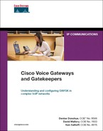
The popularity of MPLS is growing due not only to its ability to provide full-mesh connectivity, but also for its ability to provide differing levels of service for user traffic. This makes it ideal for intraoffice voice and video, in addition to data. However, cooperation is needed between the company and the service provider to ensure consistent treatment of traffic throughout the MPLS network. It is not enough for each site to regulate the way it sends traffic out its own WAN interface, because the service provider routers are also involved in the equation. Consider a simple MPLS network such as the one shown in Figure 8-1.
Figure 8-1. A Simple MPLS Network
In this situation, the company has three sites. Each site has a DS3 WAN link to the MPLS network. Notice the different routers involved. Each company site has an edge router—the customer edge (CE) router. Each CE router has a DS3 link to a provider edge (PE) router. Within the provider network are multiple provider (P) routers, in addition to other devices. Suppose that a videoconference is held between users in New York and Lima. QoS on the WAN interface of each CE router ensures that the video traffic has the right amount of bandwidth as it leaves the site. However, what if a user at Shanghai starts a large data file download from New York? QoS on the CE3 router, which does not have the video traffic, would not hinder the download. If the PE router to New York does not have QoS controls configured on it, that data traffic could monopolize the bandwidth on the PE1 to CE1 link. At the very least, it would cause jitter and a high drop rate for the videoconference. A better solution is for the MPLS provider to honor the customer DSCP markings and guarantee bandwidth to the video traffic. You must do this at the egress from the PE router to the CE router, and between the P routers within the MPLS network.
MPLS providers typically have a limited number of service levels, and their equipment is programmed to respond to specific DSCP values. Many companies find it easiest to just adopt the service provider marking throughout their own network. But that is not always the best design for every network. Companies that administer their own MPLS network must also plan how to provide the needed levels of service.
Proper planning can make this a lot easier. Keep the MPLS service classes in mind when you plan your internal QoS classes. Consider the company in the example with three large sites connected with an MPLS network. When the IT staff analyzes their traffic, they find IP voice and video conferencing—each with its own signaling, stock market data, SQL database data, e-mail, web browsing, network management, and other miscellaneous traffic. They decide to use the following classes and DSCP values within their network:
• Voice bearer—EF
• Video—AF41
• Market data—AF32
• Network management—AF33 (they also put routing updates, which are marked at CS6, in this class)
• SQL database—AF21
• Email—AF23
• Best effort (for all other traffic)—0
This company has selected a service provider that has four CoS levels available:
• Real-time—EF or CS5
• Mission Critical—AF31
• Business Critical—AF21
• Other—0
This creates a problem because the company has eight types of traffic that must be provided different QoS levels within its internal network. Clearly, the service provider is not going to change its setup, so the company must map its traffic to the service provider classes before sending it into the MPLS cloud. At each site, it also needs to reclassify the traffic back into its original seven groups and remark it accordingly.
The company decides to place voice, video, and call signaling in the real-time, prioritized class. It would not be a good idea to mix voice and video over a slow link (less than 768 kbps), because video packets tend to be large and thus take longer to serialize onto the link than small voice packets. It might introduce delay and jitter into voice calls if they share a queue. In this example, each site has a DS3 to the MPLS network, so serialization problems are not an issue. Voice retains its EF marking; video and call signaling are marked as CS5.
Market data, network management, and routing traffic go into the second class, Mission Critical. SQL and e-mail traffic go together into the Business Critical class. Both applications use TCP, so WRED is also enabled on the CE routers for this class. All other traffic goes into the Default class. WRED is also enabled on this class at the CE routers.
Voice can retain its current EF marking, but video and call signaling need to be remarked as CS5. Market data, network management, and routing traffic need to be remarked as AF31, and SQL and e-mail traffic need to be remarked as AF21. All other traffic already has a DSCP value of 0, so it does not need to be changed.
Consolidating the classes is fairly easy to do. Example 8-10 shows how to do this. Recall that class maps have two options: match all and match any. This example takes advantage of the match any option to match multiple DSCP values in one class map.
Example 8-10. Mapping Internal Classes to MPLS Classes
VGateway(config)#class-map match-all TO-MPLS-EF
VGateway(config-cmap)#match dscp ef
!
VGateway(config)#class-map match-any TO-MPLS-CS5
VGateway(config-cmap)#match dscp af41
VGateway(config-cmap)#match dscp cs3
!
VGateway(config-cmap)#class-map match-any TO-MPLS-AF31
VGateway(config-cmap)#match dscp af32
VGateway(config-cmap)#match dscp af33
VGateway(config-cmap)#match dscp cs6
!
VGateway(config-cmap)#class-map match-any TO-MPLS-AF21
VGateway(config-cmap)#match dscp af21
VGateway(config-cmap)#match dscp af23
The basic purpose behind identifying traffic is to configure the router to treat that traffic a certain way. You can manipulate data based on its markings in many ways, such as prioritizing it, guaranteeing bandwidth, policing to a specific bandwidth, dropping it, dropping random packets, or remarking it, as Example 8-11 shows. In the MQC, you do this using a policy map. After you have created the class maps that group the traffic, you use a policy map to change the DSCP values and allocated bandwidth.
Example 8-11. Marking the MPLS DSCP Values with a Policy Map
VGateway(config)#policy-map TO-MPLS
VGateway(config-pmap)#class TO-MPLS-EF
VGateway(config-pmap-c)#priority percent 18
VGateway(config-pmap-c)#set dscp ef
!
VGateway(config-pmap)#class TO-MPLS-CS5
VGateway(config-pmap-c)#priority percent 15
VGateway(config-pmap-c)#set dscp cs5
!
VGateway(config-pmap-c)#class TO-MPLS-AF31
VGateway(config-pmap-c)#bandwidth percent 12
VGateway(config-pmap-c)#set dscp af31
!
VGateway(config-pmap-c)#class TO-MPLS-AF21
VGateway(config-pmap-c)#bandwidth percent 10
VGateway(config-pmap-c)#set dscp af21
VGateway(config-pmap-c)#random-detect
!
VGateway(config-pmap-c)#class class-default
VGateway(config-pmap-c)#set dscp 0
VGateway(config-pmap-c)#fair-queue
VGateway(config-cmap)#random-detect
Then you apply this policy map to the WAN interface, outbound, with the following commands:
VGateway(config)#int atm 1/0.110 point-to-point
VGateway(config-subif)#pvc 10/110
VGateway(config-if-atm-vc)#service-policy output TO-MPLS
As a result, traffic from the eight internal QoS classes is mapped to the four classes of the MPLS provider. These same commands are needed on every CE router, applied outbound on the WAN interface. This is fairly easy. However, you must break the traffic back out into the original eight classes when it arrives at its destination CE router. That is a little more involved.
Recall that several types of traffic are sharing the same DSCP value. You must find a way to distinguish between them so that you can group them into the correct class inside the network. In the first group, identifying voice is no problem because it retained its previous marking of EF. Video and call signaling were given the same DSCP value, CS5, and placed into the same class as voice. An access list is used to break out call signaling traffic. Video uses RTP, so you can identify it in that way.
Three types of traffic are in the second group: routing, market data, and network management. The routing protocol used is Border Gateway Protocol (BGP), which you can identify by an access list. The market data uses several different ports, but all traffic is bound either to or from a specific subnet of servers. An access list can also be used to identify them. After those two are broken out, any other traffic with DSCP AF31 must be network management traffic.
The third group consists of SQL and e-mail traffic. The SQL servers share a subnet with the e-mail servers, so a simple access list specifying address is not enough. Fortunately, the Structured Query Language (SQL) and Simple Mail Transfer Protocol (SMTP) ports are both known, so you can use them to identify their respective traffic.
Example 8-12 shows how this might look when you put it all together. In this example, the policy is applied to the CE router at New York, where the servers are located. The access lists at the other sites need to flip the source and destination addresses and ports.
Example 8-12. Mapping MPLS Classes Back to Internal Classes
! This is the first group:
VGateway(config)#ip access-list extended SCCP
VGateway(config-ext-nacl)#permit tcp any any range 2000 2002
!
VGateway(config-ext-nacl)#ip access-list extended RTP
VGateway(config-ext-nacl)#permit udp any any range 16383 32767
!
VGateway(config-ext-nacl)#class-map VOICE
VGat VGateway(config-cmap)#match dscp ef
!
VGateway(config-cmap)#class-map match-all MPLS_CALL_SIG
VGateway(config-cmap)#match dscp cs5
VGateway(config-cmap)#match access-group name SCCP
!
VGateway(configs-cmap)#class-map match-all MPLS_VIDEO
VGateway(config-cmap)#match dscp cs5
VGateway(config-cmap)#match access-group name RTP
!
! This is the second group:
VGateway(config)#ip access-list extended BGP
VGateway(config-ext-nacl)#permit tcp any any eq bgp
VGateway(config-ext-nacl)#permit tcp any eq bgp any
!
VGateway(config-ext-nacl)#ip access-list extended Market-Data
! The following is the Market Data server subnet
VGateway(config-ext-nacl)#permit ip any 10.1.17.0 0.0.0.255
!
VGateway(config-cmap)#class-map match-all Routing
VGateway(config-cmap)#match dscp af31
VGateway(config-cmap)#match access-group name BGP
!
VGateway(config-cmap)#class-map match-all Mkt-Data
VGateway(config-cmap)#match dscp af31
VGateway(config-cmap)#match access-group name Market-Data
!
VGateway(config-cmap)#class-map Network-Mgmt
VGateway(config-cmap)#match dscp af31
!
! This is the third group:
VGateway(config)#ip access-list extended SQL
VGateway(config-ext-nacl)#permit tcp any any eq 1433
!
VGateway(config-ext-nacl)#ip access-list extended SMTP
VGateway(config-ext-nacl)#permit tcp any any eq 25
!
VGateway(config-cmap)#class-map match-all SQL
VGateway(config-cmap)#match dscp 21
VGateway(config-cmap)#match access-group name SQL
!
VGateway(config-cmap)#class-map match-all EMAIL
VGateway(config-cmap)#match dscp 21
VGateway(config-cmap)#match access-group name SMTP
With the access lists and class maps, you now can classify the traffic incoming from the MPLS cloud into groups that correspond to your company policy. You do this using a policy map, as shown in Example 8-13.
Example 8-13. Converting MPLS Markings to Internal Markings
VGateway(config)#policy-map FROM-MPLS
VGateway(config-pmap)#class VOICE
VGateway(config-pmap-c)#set dscp ef
!
VGateway(config-pmap-c)#class MPLS_CALL_SIG
VGateway(config-pmap-c)#set dscp cs3
!
VGateway(config-pmap-c)#class MPLS_VIDEO
VGateway(config-pmap-c)#set dscp af41
!
VGateway(config-pmap-c)#class Routing
VGateway(config-pmap-c)#set dscp cs6
!
VGateway(config-pmap-c)#class Mkt-Data
VGateway(config-pmap-c)#set dscp af32
!
VGateway(config-pmap-c)#class Network-Mgmt
VGateway(config-pmap-c)#set dscp af33
!
VGateway(config-pmap-c)#class SQL
VGateway(config-pmap-c)#set dscp 21
!
VGateway(config-pmap-c)#class EMAIL
VGateway(config-pmap-c)#set dscp 23
!
VGateway(config-pmap-c)#class class-default
VGateway(config-pmap-c)#set dscp 0
!
VGateway(config-pmap-c)#interface ATM1/0.110
VGateway(config-subif)#pvc 10/110
VGateway(config-if-atm-vc)#service-policy input FROM-MPLS
You apply the policy map inbound on the interface so that it affects traffic coming in from the MPLS cloud. Notice that policy map FROM-MPLS just sets DSCP values; it does not allocate bandwidth or prioritize traffic. Those tasks must be done at the outbound interfaces.
After the entire configuration is done, each CE router has two service policies on its WAN interface, as shown in Figure 8-2. The outbound policy aggregates the internally used classes of the company into ones that map to the standards of the MPLS provider. It remarks DSCP values where necessary. The inbound policy looks at the traffic coming from the MPLS cloud and then reclassifies and remarks it to comply with the internal QoS policy of the company.
Figure 8-2. Mapping QoS to MPLS Standards
As stated earlier, it is important to thoughtfully plan your QoS strategy. You need to decide how to group traffic and what DSCP value to give to each of those groups. This is not a trivial task.
Link Fragmentation and Interleave
Voice and video traffic are sensitive to delay and jitter. You might recall that the delay target for voice is 150 ms, and for jitter it is 30 ms. LLQ, as described in the previous section, is one way to cut down on delay and jitter. When voice traffic is placed into an LLQ, it is sent out before other traffic. However, suppose that a small voice packet arrives at an interface just after a large data packet has begun being placed on the wire (or serialized). Even though the voice packet is placed in the priority LLQ, transmission of the data packet is not going to stop. The voice packet has to wait. This can be another cause of delay and jitter.
The time it takes for a packet to be placed onto the wire is known as serialization delay. This value varies by speed of the link and size of the packet. Naturally, any size packet takes longer to transmit out a slower interface than a faster one. And the more bits that must be transmitted out an interface, the longer it takes. To meet the requirements for voice, each interface along the path has a target serialization delay of no more than 10 ms. In the LAN, links are fast enough that serialization delay is not a factor. But on WAN links, it can be an issue.
One way to solve this is to break up large data packets into smaller pieces that take no more than 10 ms to serialize, which is known as fragmentation. Then voice packets can be transmitted between each piece of the data packet, which is known as interleaving. When combined, the technique is known as Link Fragmentation and Interleave.
You can calculate an approximate value for serialization delay using the following formula:
([packet-size * 8]/link-speed)
Packet size is in bytes, so you multiply by 8 to convert it to bits. Then you divide that product by the link speed in kbps. For example, the formula for a 1500-byte packet being sent out a T1 interface (1544 kbps) would look like this:
([1500 * 8]/1544 kbps) = 7.8 ms delay
As you can see, 1500 bytes takes less than 10 ms to serialize on a T1 interface. The same number of bytes takes 15.6 ms on a 768-kbps interface, however. As a general rule, fragmentation is not recommended on interfaces of T1 speed or greater. It can be helpful on lower-speed interfaces, if they tend to carry large data packets along with voice.
This leads to the question of what size the fragments should be. Tables are available in QoS texts detailing this, but you can also estimate the correct fragment size. At 64 kbps, it takes about 10 ms to serialize 80 bytes. You can use this fact to calculate fragment size—for instance, a 256-kbps link is four times a 64 kbps one. So the packet size can be four times 80 bytes, or 320 bytes.
Fragmentation is configured in different ways depending on the type of interface. You can do it on a leased line by using Multilink PPP (MLP), on a Frame Relay circuit by using FRF.12, on a Frame Relay circuit by using Multilink PPP over Frame Relay (MLPoFR), and with ATM by using Multilink PPP over ATM (MLPoATM). (An alternative for both Frame Relay and ATM is to use separate PVCs for voice.)
Multilink PPP
Multilink PPP was created to allow multiple PPP links to be treated as one, for load balancing and ease of administration. You can also use it with a single PPP link, as the example that follows shows. One good thing about using MLP is that you do not have to figure out the desired fragment size—PPP does that for you. You only have to specify the desired serialization delay value. Configuration is done with both a logical and a physical interface. Configuring MLP involves the following steps:
Step 1. Create a logical Multilink interface. Notice that logical configurations, such as the IP address, service policy, and bandwidth, are all configured on the Multilink interface.
VGateway(config-if)#interface multilink1
VGateway(config-if)#ip address 172.18.1.1 255.255.255.252
VGateway(config-if)#service-policy output VOICE-VIDEO
VGateway(config-if)#bandwidth 768
Step 2. Enable Multilink PPP, and associate the interface with a Multilink group. Configure the desired delay on the Multilink interface.
VGateway(config-if)#ppp multilink
VGateway(config-if)#ppp multilink group 1
VGateway(config-if)#ppp multilink fragment-delay 10
Step 3. Configure interleaving on the Multilink interface.
VGateway(config-if)#ppp multilink interleave
Step 4. At the physical PPP interface, configure PPP encapsulation, and enable PPP Multilink.
VGateway(config-if)#int s 0/0
VGateway(config-if)#encapsulation ppp
VGateway(config-if)#ppp multilink
Step 5. Place the physical interface into the Multilink group that is associated with the Multilink interface created earlier.
VGateway(config-if)#ppp multilink group 1
A useful verification command for MLP is show interface multilink interface-number. Example 8-14 shows the output from this command. Link control protocol (LCP) and multilink must both be open for the interface to be active. Under the Output queue line, which is highlighted, you can see the number of interleaves performed.
Example 8-14. show interface multilink 1 Command Output
VGateway#show interface multilink 1
Multilink1 is up, line protocol is up
Hardware is multilink group interface
Internet address is 172.18.1.1/30
MTU 1500 bytes, BW 768 Kbit, DLY 100000 usec,
reliability 255/255, txload 9/255, rxload 9/255
Encapsulation PPP, LCP Open, multilink Open
Open: CDPCP, IPCP, loopback not set
Keepalive set (10 sec)
DTR is pulsed for 2 seconds on reset
Last input 00:00:04, output never, output hang never
Last clearing of "show interface" counters 01:21:31
Input queue: 0/75/0/0 (size/max/drops/flushes); Total output drops: 0
Queueing strategy: Class-based queueing
Output queue: 0/1000/64/0/138 (size/max total/threshold/drops/interleaves)
Conversations 0/2/256 (active/max active/max total)
Reserved Conversations 0/0 (allocated/max allocated)
. . .
You must do this configuration on both sides of the link for fragmentation and interleave to work properly. One caveat is that any traffic in an LLQ will not be fragmented. Because video packets can go up to 1500 bytes in size, do not place video in the LLQ on slow links.
If you must run video through an interface with less than T1 bandwidth, put it in a class-based queue and assign bandwidth to it.
Frame Relay FRF.12 Fragmentation
FRF.12 is a standards-based way to do fragmentation on Frame Relay links. This standard allows you to fragment and interleave long frames with smaller frames at Layer 2. Frame Relay does not look into the packets to see whether traffic is voice or data. It fragments all packets larger than the specified size, regardless of what payload they carry. Therefore, be sure to configure a fragment size larger than the biggest voice traffic, with headers included.
Fragmentation is configured at the PVC level and applied to all traffic within that PVC. If multiple PVCs share the same physical interface, configure fragmentation on all of them because they share the same transmit ring at the interface. If any PVCs send large unfragmented frames, it could delay the voice traffic. Configure fragmentation on routers at both ends of the PVC, because it is end to end. Frames are fragmented at one router, and reassembled by the router on the other end of the virtual circuit. A special FRF.12 header is put on traffic from the PVC when fragmentation is configured.
When you are sending VoFR, shape the traffic from each PVC to avoid drops or delays from buffering within the provider cloud. Frame Relay traffic shaping (FRTS) causes the router to control the amount of traffic sent out the interface so that it conforms to the committed information rate (CIR) of each PVC. The traditional way to configure shaping is to place the commands under a Frame Relay map class. However, current versions of the Cisco IOS can do class-based FRTS. Configuring class-based Frame Relay fragmentation and shaping involves the following steps:
Step 1. Configure a policy map that puts voice in an LLQ and sets policies for other traffic as desired. Be sure that the total bandwidth allocated does not exceed the circuit CIR.
VGateway(config)#policy-map LLQ
VGateway(config-pmap)#class VOICE
VGateway(config-pmap-c)#priority 128
Step 2. Configure a second policy map. Configure traffic shaping parameters under the default class. In the following output, the first number is the configured CIR, in bits per second. Cisco recommends configuring the CIR to be 95 percent of the actual CIR to allow for overhead. The second number is the number of bits allowed per interval. Set this to the CIR/100, which forces that interval to be 10 ms. The last number is the excess burst (Be) allowed. Set this to 0 when sending VoIP over Frame Relay.
Gateway(config-pmap-c)#policy-map SHAPE
VGateway(config-pmap)#class class-default
VGateway(config-pmap-c)#shape average 729600 7296 0
Step 3. Associate the first policy map with the second under the default class.
VGateway(config-pmap-c)#service-policy LLQ
Step 4. Configure a Frame Relay map class. Configure the fragmentation parameter under this map class and associate the service policy with it. Set the fragment size to 960 by using the method given in the “Link Fragmentation and Interleave” section earlier in this chapter. Take advantage of the fact that at 64 kbps, it takes about 10 ms to serialize 80 bytes. The link speed in this example is 768 kbps. Thus, 768 divided by 64 equals 12. Multiplying 80 bytes times 12 gives you a fragment size of 960 bytes.
VGateway(config)#map-class frame-relay LFI-SHAPE
VGateway(config-map-class)#frame-relay fragment 960
VGateway(config-map-class)#service-policy output SHAPE
Step 5. Associate the map class with a PVC:
VGateway(config)#interface s0/0.112 point-to-point
VGateway(config-subif)#frame-relay interface-dlci 112
VGateway(config-fr-dlci)#class LFI-SHAPE
You can verify the configuration by the output of the show policy interface command, as follows in Example 8-15.
Example 8-15. show policy interface Command Output
VGateway#show policy interface s0/0.112
Serial0/0.112: DLCI 112 -
Service-policy output: SHAPE
Class-map: class-default (match-any)
0 packets, 0 bytes
5 minute offered rate 0 bps, drop rate 0 bps
Match: any
Traffic Shaping
Target/Average Byte Sustain Excess Interval Increment
Rate Limit bits/int bits/int (ms) (bytes)
729600/729600 1825 7296 7296 10 912
Adapt Queue Packets Bytes Packets Bytes Shaping
Active Depth Delayed Delayed Active
- 0 0 0 0 0 no
Service-policy : LLQ
Class-map: VOICE (match-all)
0 packets, 0 bytes
5 minute offered rate 0 bps, drop rate 0 bps
Match: access-group name RTP
Queueing
Strict Priority
Output Queue: Conversation 72
Bandwidth 128 (kbps) Burst 3200 (Bytes)
(pkts matched/bytes matched) 0/0
(total drops/bytes drops) 0/0
Class-map: class-default (match-any)
0 packets, 0 bytes
5 minute offered rate 0 bps, drop rate 0 bps
Match: any
The show frame-relay fragment command lets you monitor the fragmentation occurring, as shown in Example 8-16. You can obtain more detailed information by specifying an interface after the command.
Example 8-16. show frame-relay fragment Command Output
VGateway#show frame-relay fragment
interface dlci frag-type size in-frag out-frag dropped-frag
Se0/0.112 112 end-to-end 960 0 0 0
Frame Relay Fragmentation Using MLPoFR
Link fragmentation and interleave can be done over Frame Relay using MLPoFR. Instead of creating a Multilink interface, the logical interface is called a Virtual-Template. Example 8-17 shows the configuration needed. You create a Virtual-Template interface and give almost the same configuration as shown in the Multilink interface example in the preceding “Multilink PPP” section. Fragmentation delay is specified, as is interleaving. The service policy LLQ is associated with this Virtual-Template interface, not the physical interface.
Example 8-17. Configuring MLPoFR
VGateway(config)#interface virtual-template1
VGateway(config-if)#
00:10:39: %LINK-3-UPDOWN: Interface Virtual-Template1, changed state to down
VGateway(config-if)#bandwidth 768
VGateway(config-if)#ip address 172.18.1.1 255.255.255.252
VGateway(config-if)#ppp multilink
VGateway(config-if)#ppp multilink fragment delay 10
VGateway(config-if)#ppp multilink interleave
VGateway(config-if)#service-policy output LLQ
!
VGateway(config-if)#map-class frame-relay MLPoFR
VGateway(config-map-class)#frame-relay cir 729600
VGateway(config-map-class)#frame-relay bc 7296
VGateway(config-map-class)#frame-relay be 0
VGateway(config-map-class)#no frame-relay adaptive-shaping becn
!
VGateway(config-map-class)#)#interface s0/0
VGateway(config-if)#encapsulation frame-relay
VGateway(config-if)#frame-relay traffic-shaping
!
VGateway(config-if)#interface s0/0.112 point-to-point
VGateway(config-subif)#frame-relay interface-dlci 112 ppp virtual-template1
Class Based Weighted Fair Queueing will be applied only to the Virtual-Access
interfaces associated with an MLP bundle.
VGateway(config-fr-dlci)#
00:38:48: %LINK-3-UPDOWN: Interface Virtual-Access2, changed state to up
VGateway(config-fr-dlci)#class MLPoFR
A Frame Relay map class, MLPoFR, is configured with shaping parameters. Under that map class, the CIR is set to 95 percent of the link speed of 768 kbps to allow for overhead. Committed burst (Bc) is set to link-speed/100 to force the burst interval to be 10 ms. No Be is allowed. Adaptive traffic shaping in response to backward explicit congestion notification (BECN) frames is disabled.
Enable Frame Relay traffic shaping on the physical interface and apply the map class to the PVC. Notice the command to associate that PVC with the Virtual-Template interface: frame-relay interface-dlci dlci-number ppp virtual-template1. When MLPoFR is configured, the router automatically creates two additional logical interfaces: Virtual-Access1 and Virtual-Access2. (Notice in the example the message saying that interface Virtual-Access2 is up.) Virtual-Access1 is a logical PPP interface, and Virtual-Access2 is a logical Multilink PPP Bundle interface. You can verify this by looking at the output from a show interface command. The router messages shown are normal.
MLPoATM
You can also use MLP with an ATM PVC. Using MLPoATM allows ATM traffic to be fragmented and interleaved, something that ATM itself cannot accomplish. The most frequently used ATM adaptation layers assume that cells will arrive in the correct order, so they do not place a sequence number on the cells. Interleaving would make the cells arrive out of order. MLP handles the fragmenting, interleaving, sequence numbering, and reordering of the cells transparently to ATM.
When using MLPoATM, a Virtual-Template interface is created with the same commands as with MLPoFR. As a reminder, Example 8-18 shows the configuration.
Example 8-18. Configuring MLPoATM
VGateway#show run interface virtual-template1
interface Virtual-Template1
bandwidth 768
ip address 172.18.1.1 255.255.255.252
ppp multilink
ppp multilink fragment delay 10
ppp multilink interleave
service-policy output LLQ
VGateway(config)#interface atm 1/0
VGateway(config-if)#bandwidth 768
!
VGateway(config-if)#interface atm 1/0.110 point-to-point
VGateway(config-subif)#pvc 10/110
VGateway(config-if-atm-vc)#vbr-nrt 768 768
VGateway(config-if-atm-vc)#protocol ppp virtual-template1
VGateway(config-if-atm-vc)#tx-ring-limit 3
There is no equivalent to a Frame-Relay map class needed to specify shaping parameters; instead, you configure shaping parameters under the virtual circuit configuration, as shown in Example 8-18. The example PVC uses variable bit rate, nonreal-time (VBR-nrt). The first number is the peak cell rate (PCR), the maximum rate at which you expect to transmit traffic. The second number is the sustainable cell rate (SCR), which is the bandwidth of the virtual circuit. Setting the PCR and SCR to the same value effectively eliminates bursts, causing traffic to be shaped to a constant rate.
If you are experiencing excessive delay when using VoIP with ATM, try lowering the size of the interface transmit ring. Generally, setting the transmit ring size to 3 or 4 particles works well for voice. You do that under the virtual circuit configuration, as shown in Example 8-18.
Commands to verify the configuration include show atm vc and show policy-map interface.
Compression
Another way to lower serialization delay values is to send smaller packets. The payload in voice packets tends to be fairly small. However, each packet has to carry an IP header, a UDP header, and an RTP header that totals 40 bytes of overhead. When voice is sent across a WAN, it is usually compressed using G729, with a payload of 20 bytes. Thus, the headers are twice the size of the payload. Most of the header information in any given conversation is the same, so it can be reliably compressed. Compressed RTP (cRTP) compresses the IP, UDP, and RTP headers; it does not change the payload. With cRTP you can usually reduce the three headers to 2 bytes when checksum data is not sent, and 4 bytes when checksums are used. As you can imagine, this is especially helpful on slow links.
You can enable RTP compression on a Frame Relay, high-level data link control (HDLC), PPP, or MLP link. It is configured either at the interface level, on a particular virtual circuit, or for a class of traffic using the MQC. You must enable RTP compression on routers at both ends of a link, because each router in the path needs to uncompress the headers to know how to route the data.
Use cRTP with slow links, small voice payloads, and a need to save bandwidth. It is typically not needed on links over 2 Mbps in speed. Compression and decompression do use router resources, with more resources used the more calls you have. The trade-off in router performance is usually not worth the gain in bandwidth with link speeds over 2 Mbps. Understand that cRTP only compresses the headers for RTP traffic, not other types of data. If fast-switching or Cisco Express Forwarding (CEF) is enabled on the interface, compression is done on these paths. If neither is enabled on the interface, traffic that needs to be compressed is process switched.
To enable CRTP on an HDLC or PPP serial interface, use the following command under the physical interface configuration:
ip rtp header-compression [passive]
If you include the optional passive keyword, the router does CRTP only if it receives compressed packets.
To enable CRTP on a Frame Relay interface, use the following command:
frame-relay ip rtp header-compression [passive]
You can configure the preceding command either under the physical interface configuration or under the subinterface.
If this command is given on the physical Frame Relay interface, all PVCs that are associated with that interface inherit it.
MQC class-based compression allows more granular control of RTP compression. It is configured in a policy map and applies only to RTP traffic in the specific class(es) where it is enabled. For instance, in the following commands, RTP header compression is enabled for all traffic in the Voice class. If the rtp keyword is not specified, both RTP and TCP header compression are done. You should also configure the gateway to place this traffic in the LLQ.
VGateway(config)#policy-map VOICE-VIDEO
VGateway(config-pmap)#class Voice
VGateway(config-pmap-c)#compression header ip rtp
Then you can apply the policy outbound to an interface, virtual circuit, Frame Relay map class, or virtual interface. You can verify your configuration with the show policy-map and show policy interface commands, as shown in Example 8-19.
Example 8-19. Verifying RTP Compression
VGateway#show policy VOICE-VIDEO
Policy Map VOICE-VIDEO
Class Voice
Strict Priority
Bandwidth 15 (%)
compress:
header ip rtp
VGateway#
VGateway#show policy interface s0/0
Serial0/0
Service-policy output: VOICE-VIDEO
Class-map: Voice (match-all)
2153 packets, 137792 bytes
5 minute offered rate 10000 bps, drop rate 0 bps
Match: dscp ef (46)
Queueing
Strict Priority
Output Queue: Conversation 264
Bandwidth 15 (%)
Bandwidth 231 (kbps) Burst 5775 (Bytes)
(pkts matched/bytes matched) 2152/36584
(total drops/bytes drops) 0/0
compress:
header ip rtp
UDP/RTP compression:
Sent: 2152 total, 2147 compressed,
101208 bytes saved, 36584 bytes sent
AutoQos
Cisco has an AutoQoS feature that you can enable. When enabled, this feature configures QoS policies for the device in accordance with Cisco best practices. It is useful for network administrators who do not have in-depth knowledge of QoS techniques, such as those discussed in this chapter, or for those who need to deploy QoS quickly.
AutoQoS has the following features when used at a WAN voice gateway router:
• It uses the MQC.
• It creates class maps to classify voice-bearer and voice-control traffic, in addition to other traffic.
• It creates policy maps that place voice traffic in an LLQ and guarantee bandwidth to voice control traffic.
• Frame Relay traffic shaping is configured for Frame Relay links.
• Link Fragmentation and Interleaving (LFI) and RTP header compression are configured for links under 768 kbps.
• When you are using LFI, any IP address that is configured under the subinterface is automatically moved to the multilink or Virtual-Template interface.
• It supports Frame Relay, ATM, Frame Relay-to-ATM Internetworking, PPP, and HDLC links.
• It can send SNMP and SYSLOG notices for such things as VoIP packet drops.
AutoQos is configured on a WAN interface, subinterface, or PVC with the following command:
auto qos voip [trust] [fr-atm]
The optional keyword trust tells the router to trust the DSCP markings that are already on the traffic. The default is not to trust those markings, but to remark traffic based on its type. AutoQos uses Network-Based Application Recognition (NBAR) to determine types of traffic. The optional fr-atm keyword is used with low-speed Frame Relay PVCs that participate in Frame Relay-to-ATM Internetworking. You must manually configure bandwidth on the interface or subinterface when you are using AutoQoS.
Using AutoQos can be helpful, but a basic understanding of good QoS practices is still important. You might need to tweak the automatic configuration to suit the exact needs of your company. In addition, it is always good to understand what is happening in your network.
Providing Fax and Modem Services
Analog faxes and modems provide an extra challenge in a VoIP network. These devices assume that they have a physical circuit between the transmitting and receiving ends, such as over the PSTN, but IP networks do not provide this. Thus, fax and modem data requires special handling when sending over an IP network. There are two basic methods for handing fax and modem calls:
• Relay—The analog data is demodulated by the sending gateway, which packetizes the data and sends it over the IP network. The receiving gateway remodulates it and forwards it as analog data to the fax or modem. The actions of the gateways are transparent to the end devices—they receive analog data just as if they were communicating over a PSTN link. In general, relay is not as affected by packet loss, delay, and jitter as is passthrough. It also uses less bandwidth.
• Passthrough—Fax and modem calls are treated as any other analog voice call, with the data carried in-band in RTP packets to the remote fax or modem. This requires the G.711 codec, no echo cancellation, and no voice activity detection (VAD). When the gateways recognize the type of call, they change to these settings for the duration of the call. Passthrough is sensitive to packet loss, delay, and jitter. You can use redundancy with passthrough to send an extra copy of each packet, to help mitigate packet loss. This does result in higher bandwidth use, however.
Note
A third method, Store and Forward, is used only for faxes. It uses a separate e-mail server and allows faxes to be sent as TIFF attachments to e-mails. You can use Toolkit Command Language (Tcl) scripts to provide some fax-related services, also. Tcl interactive voice response (IVR) scripts are typically used with Store and Forward faxing. Tcl scripts can also provide fax detection and fax rollover applications. Fax detection allows one phone number to be used for both voice and fax calls. Fax rollover involves switching to Store and Forward mode if fax relay fails. See Chapter 15, “Using TCL Scripts and VoiceXML,” for more information on Tcl scripts for fax applications.
Providing Fax Services
Several standards govern fax transmissions. It is not necessary to know all of them to get faxes working over IP, but an understanding of the major ones helps. International Telecommunications Union Telecommunication Standardization Sector (ITU-T) standards govern such things as fax resolution, identifying tones, handshaking procedures, and transmission speeds. They have developed over time from Group 1 to Group 3 standards. The Group 3, or “G3,” standard is currently the most commonly used. It allows fax transmission rates over analog lines of up to 14,400 bps. Group 4 (G4) is a standard for transmitting faxes over ISDN, and it can send at a rate of 64,000 bps. By using two B-channels, G4 faxes can send and receive at the same time. Super G3 (SG3) is a newer standard, which allows sending faxes at 33,600 bps.
Session management between two G3 fax machines is specified in the T.30 standard of the ITU-T, and T.4 describes the image transmission. Communication between gateways using fax relay is standardized by T.38.
T.30 divides fax calls into five phases:
• Phase A: Call Setup—In Phase A, a call is established, and the two endpoints identify themselves as fax machines. The calling device repeatedly sends a CalliNG (CNG) tone. The called device sends a Called Station Identification (CED) tone. After the devices exchange these tones, they know that they are communicating with a fax machine.
• Phase B: Capabilities Exchange—The called machine sends a V.21 standard Digital Identification Signal (DIS), which lists its capabilities, such as page length, resolution, error correction, and handshake speed. When the gateway sees this DIS message, it switches the call from a voice codec to a fax codec.
The calling machine responds with a Digital Command Signal (DCS), telling the called device which of its settings to use. The calling machine then sends a Training Check Field (TCF) signal at the agreed-upon modulation. If the called machine receives this properly, it responds with a Confirmation to Receive (CFR) message. Otherwise, it sends a Failure to Train (FTT).
• Phase C: Data Transmission—The T.4 standard specifies message transmission standards. It handles such things as encoding type and error correction. At the end of the transmission, the fax sends a Return to Control (RTC) message, which initiates Phase D.
• Phase D: Confirming the Transmission—After the sending fax has returned to control mode, it sends a message that it has finished transmitting. The receiving fax responds with a Message Confirmation (MCF).
• Phase E: Releasing the Call—Either fax machine can send a Disconnect (DCN) message. Both sides then release the call.
Phases A and B are handled differently in Super G3 faxes. In Phase A, the called device sends a Modified Answer (ANSam) tone instead of a CED tone. In Phase B, the calling device sends a Call Menu message, and the called fax responds with a Joint Menu message. If the SG3 handshake does not succeed, the fax machines fall back to G3 mode. These differences in operation might require some special configuration, as you will see in the following sections.
You can configure the type of fax treatment used in two places: under an individual dial peer, or in the voice service voip configuration mode. The command syntax is fax protocol {cisco | none | pass-through {g711ulaw | g711alaw}| system | t38}. The exact options available vary by Cisco IOS version.
Configuring Cisco Fax Relay
Cisco gateways use two versions of fax relay: the Cisco proprietary version, and one that uses the ITU-T T.38 standard. Cisco fax relay is the default way of handling faxing by Cisco gateways. It uses RTP to exchange the demodulated T.30 fax signals with its peer gateway. Cisco fax relay is supported on most Cisco gateways, with the exception of some models in the AS5000 series. It does not need to be enabled, unless you have used a different method and want to re-enable it. The command to enable Cisco fax relay is fax protocol cisco. You can give this command under an individual dial peer, or under voice service voip configuration mode to affect all dial peers.
You can tweak Cisco fax relay in a few ways. For instance, Error Correction Mode (ECM) is enabled by default. Fax machines that use ECM require any frames that have errors to be retransmitted. If the fax cannot receive an error-free page, it might terminate the call. In networks that have more than two percent packet loss, you might see a high rate of fax failure because of ECM. If you disable it, more faxes succeed, although they might contain some errors. Disable ECM with the VoIP dial peer command fax-relay ecm disable.
Some fax machine manufacturers use proprietary features, which are negotiated during Phase B using an optional Non-Standard Facilities (NSF) field. The Cisco fax relay handles fax calls based on T.30 standards, and thus cannot interpret these capabilities. You can cause the gateway to overwrite the NSF field with zeros using the VoIP dial peer command fax nsf 000000.
You might need to change the rate at which faxes are sent. By default, faxes use the same bandwidth as voice calls. In networks that use low-bandwidth codecs, such as G.729, this might cause faxes to transmit too slowly. Also, some fax machines might operate better at a different speed than the default. You can change fax bandwidth for a VoIP dial peer with the command fax rate {speed | disable | voice}, where speed is a value from 2400 to 14400 bps, disable disables all fax transfer methods, and voice uses the voice call bandwidth. This command is also valid for T.38 fax relay.
In Example 8-20, Cisco fax relay is enabled, ECM is disabled, use of proprietary features is disabled, and the fax rate is set at 14400 bps.
Example 8-20. Configuring Cisco Fax Relay
VoiceGW(config)#dial-peer voice 4000 voip
VoiceGW(config-dial-peer)#fax protocol cisco
VoiceGW(config-dial-peer)#fax-relay ecm disable
VoiceGW(config-dial-peer)#fax nsf 000000
VoiceGW(config-dial-peer)#fax rate 14400
Configuring T.38 Fax Relay for MGCP Gateways
T.38 is a standards-based type of fax relay, which treats the communication between gateways differently from Cisco fax relay. After the gateway demodulates the T.30 messages from the fax machine, it translates them into T.38 Internet Fax Protocol (IFP) packets for transmission to its peer gateway. When the other gateway receives these packets, it translates them back into T.30 signals and sends those to the fax machine.
T.38 fax relay is handled differently on MGCP gateways than on H.323 and SIP gateways. MGCP gateways can rely on the call agent to direct the T.38 traffic flow, when using call agent (CA)-controlled fax relay mode. They can also make those decisions themselves, when using gateway-controlled fax relay mode.
In gateway-controlled mode, fax relay capabilities are exchanged in the Session Description Protocol (SDP) packets during call setup. If both gateways support fax relay, they signal the switch to T.38 using Named Service Event (NSE) or Named Telephony Event (NTE) messages after they detect a DIS fax tone. NSE messages are a Cisco-proprietary form of NTE messages. They are used to send call signaling that would be sent using tones, such as fax tones, in a non-VoIP network. The content of the NSE messages has information to allow the receiving gateway to re-create the original tones. NSE and NTE messages travel in the RTP stream, but they use a different RTP payload type (usually 100) to distinguish them from voice packets. NSE and NTE differ in the values used to represent tones and events.
If neither gateway supports fax relay, the gateways fall back to fax passthrough. The CA knows only that a voice call exists; the fact that it is a fax call is transparent to it. T.38 fax relay is disabled by default on MGCP gateways using auto-configuration before Cisco IOS 12.4T, and it is enabled on Cisco IOS versions after that.
You can make some adjustments to MGCP T.38 with the global command mgcp fax t38 {ecm | gateway force | hs_redundancy value | inhibit | ls_redundancy value | nsf hexcode}, where
• ecm enables error correction mode.
• gateway force forces the gateway to use T.38 and NSEs even if they are not negotiated during call setup. This allows MGCP gateways to use T.38 fax relay with H.323 and SIP gateways.
• hs-redundancy factor causes the router to send redundant packets when doing high-speed faxing, to cover for any dropped packets. The default value is 0, which means no redundancy.
• inhibit disables T.38 fax relay on the gateway. To enable T.38 fax relay, use the command no mgcp fax t38 inhibit.
• ls-redundancy causes the router to send redundant packets when doing low-speed faxing, to cover for any dropped packets. The default value is 0, which means no redundancy.
• nsf hexcode disables the use of proprietary fax features when the hexcode used is 000000.
Use the show mgcp command to verify your configuration, as shown in Example 8-21. Only relevant portions of the lengthy output are displayed. Note that MGCP T.38 commands are given at the global configuration mode.
Example 8-21. Configuring MGCP T.38 Fax Relay
VoiceGW(config)#no mgcp fax t38 inhibit
VoiceGW(config)#no mgcp fax t38 ecm
VoiceGW(config)#^Z
VoiceGW#show mgcp
...
MGCP TSE payload: 100
MGCP T.38 Named Signalling Event (NSE) response timer: 200
...
MGCP T.38 Fax is ENABLED
MGCP T.38 Fax ECM is DISABLED
MGCP T.38 Fax NSF Override is DISABLED
MGCP T.38 Fax Low Speed Redundancy: 0MGCP T.38 Fax High Speed Redundancy: 0
Configuring T.38 Fax Relay for H.323 and SIP Gateways
H.323 and SIP gateways use the same basic configuration for T.38 fax relay. They do not use NSE messages to signal the other gateway to switch to fax mode, unless you specifically configure it. Instead, they use H.323 or SIP messages. Configure dial peers for fax destinations, enable T.38 fax relay, and set parameters under each dial peer. If several dial peers share the same T.38 settings, you might prefer to configure them globally under the voice service voip mode instead. Dial peer configuration takes precedence over global configuration if both exist.
The command to configure T.38 fax relay under a dial peer is fax protocol {system | t38 [nse [force]] [ls-redundancy value [hs-redundancy value]] [fallback {cisco | none | pass-through {g711ulaw | g711alaw}}]}, where
• system is the default. It causes the dial peer to use the global fax protocol that is configured.
• t38 tells the dial peer to use T.38 fax relay. The nse option to this command negotiates the use of NSE messages to signal the switch to fax relay. The force option requires the use of NSE messages, even if the other side does not signal that capability. This allows H.323 and SIP gateways to exchange faxes with MGCP gateways.
• ls-redundancy value causes the router to send redundant packets when doing low-speed faxing, to cover for any dropped packets. The default value is 0, which means no redundancy.
• hs-redundancy value causes the router to send redundant packets when doing high-speed faxing, to cover for any dropped packets. The default value is 0, which means no redundancy.
• fallback configures a fallback way to handle faxing if the gateway cannot negotiate T.38 fax relay with its peer gateway. cisco uses Cisco fax relay, none disables fax handling, and pass-through enables fax passthrough. You must specify the codec to use—either g711ulaw or g711alaw.
The same command is available under voice service voip configuration mode, although the system option is not available. When configuring fax relay in this way, make sure that at least one dial peer matches the incoming calls. Commands that you configure under a dial peer take precedence over those you configure in voice service voip mode.
Example 8-22 shows a dial peer that is configured for T.38 fax relay. It forces the use of NSE messages and falls back to Cisco fax relay if the gateways cannot negotiate T.38.
Example 8-22. Configuring T.38 Fax Relay on H.323 and SIP Gateways
VoiceGW(config)#dial-peer voice 4000 voip
VoiceGW(config-dial-peer)#fax protocol t38 nse force fallback cisco
When you are troubleshooting T.38 fax relay, be sure that an IP path exists between the two gateways. Check that the dial peers are configured properly. The debug fax relay t30 command gives you information about the phone numbers and T.30 messages in your fax transmissions.
Note
Debug commands can affect the performance of the router.
Configuring Super G3 Fax Relay
Super G3 (SG3) fax machines negotiate the use of SG3 speed during call setup, using Call Menu and Joint Menu messages. They use the V.34 standard for modulation and the V.8 standard for signaling. V.34 is a form of pulse code modulation (PCM) that allows data transmission up to 33,600 bps. The V.8 standard describes SG3 signaling such as ANSam, Call Menu, and Joint Menu.
SG3 machines can interoperate with G3 faxes. If an SG3 machine is on one end and a G3 machine is on the other, the SG3 machine receives a DIS instead of the expected Menu message, and it falls back to G3 mode. When the gateway hears the DIS, it switches the call to a fax call. Fax relay between SG3 and G3 machines is not usually a problem in Cisco VoIP networks.
Fax relay between two SG3 machines can be a problem, however. SG3 was not designed to work with T.38 fax relay. The two fax machines exchange V.8 signaling, so the gateways never hear a DIS and do not switch the call over to fax mode. The current solution for this is SG3 fax spoofing. SG3 fax spoofing is available on most voice gateways in Cisco IOS versions 12.4(4)T and later. It blocks the Call Menu message from being sent. This causes the receiving fax machine to fall back to G3 mode and send V.21 DIS and DCS messages. Both gateways then use G3 mode.
You can configure SG3 fax spoofing on one or both gateways, but you at least must configure it on the calling gateway so that it suppresses the Call Menu message. You can configure the fax-relay sg3-to-g3 [system] command under a dial peer or in voice service voip configuration mode on H.323 or SIP gateways. Configure SG3 spoofing in global configuration mode on MGCP gateways. The “system” option is available only in dial peer configuration mode and causes the dial peer to use the protocol set in voice service voip configuration mode. Example 8-23 shows a router configured under the voice service mode to use SG3 fax spoofing.
Example 8-23. Configuring SG3 Fax Spoofing
VoiceGW(config)#voice service voip
VoiceGW(conf-voi-serv)#fax-relay sg3-to-g3
Configuring Fax Passthrough
In fax passthrough, the gateway does not demodulate the call—it treats fax calls similar to analog voice calls. Fax data is sent in-band, in RTP packets, to the other gateway. Fax passthrough uses the G.711 codec and requires 64 kbps per call, plus 32 kbps per call for overhead. Echo cancellation and VAD are turned off. Passthrough is sensitive to jitter, latency, and packet loss. You can use redundancy, which sends two copies of each packet, to mitigate packet loss, but it also requires extra network bandwidth.
Configuring Fax Passthrough for MGCP Gateways
As with fax relay, MGCP gateways use NSE messages to signal their peer to switch to fax mode. You configure fax passthrough for MGCP gateways globally rather than under the dial peer, using options of the mgcp modem passthrough command. MGCP gateways use NSE messages to signal their peer gateway to switch to fax mode. Passthrough using NSEs is called “modem passthrough”; thus, the command to configure fax passthrough on an MGCP gateway is the same command you use to configure modem passthrough. The following commands are available:
• mgcp modem passthrough {cisco | ca}—Configures the type of fax/modem passthrough used. The cisco option causes the gateway to switch to G711 codec when it detects a fax tone, and notify its peer gateway. The ca option, which is the default, causes the gateway to alert its call agent when a fax tone is detected. The call agent then signals a switch to the G711 codec.
• mgcp modem passthrough {voip | voaal2} codec {g711alaw | g711ulaw}—Configures the codec used in either VoIP or Voice over ATM Adaptation Layer 2 (VoAAL2) networks. If you do not specify the codec, the router uses G711ulaw. After the router detects fax or modem traffic, it switches to using the specified codec for that call.
• mgcp modem passthrough voip redundancy—Enables redundant fax packets to be sent, to mitigate packet loss. Redundancy is disabled by default.
• mgcp modem passthrough mode {voip | voaal2} mode {cisco | nse}—Configures the method used to signal the switch to fax speed in either VoIP or VoAAL2 networks. The cisco option uses whatever Cisco proprietary method is available. The nse option, which is the default, uses NSE messages to signal the switch. If nse is used, you can also configure the mgcp tse payload value.
• mgcp tse payload value—Enables the use of in-band Telephony Signaling Events (TSE) and specifies a payload value. Both receiving and sending gateways must use the same value; the default is 100.
Example 8-24 shows an MGCP gateway configured for fax passthrough, with redundancy, using NSE message for upspeeding. The TSE payload value is left at its default of 100. This is verified with the show mgcp command. Only the relevant output of the command is shown.
Example 8-24. Configuring MGCP Fax Passthrough
VoiceGW(config)#mgcp modem passthrough voip mode nse
VoiceGW(config)#mgcp modem passthrough voip redundancy
!
VoiceGW#show mgcp
MGCP voip modem passthrough mode: NSE, codec: g711ulaw, redundancy: ENABLED,
MGCP voaal2 modem passthrough disabled
MGCP voip modem relay: Disabled.
MGCP TSE payload: 100
Configuring Fax Passthrough for H.323 and SIP Gateways
H.323 and SIP gateways typically signal the switchover to fax mode using H.323 or SIP protocol messages. However, you can configure them to use NSE messages. Using NSEs is actually called “modem passthrough.” You must use modem passthrough when you are interacting with Cisco CallManager, because it uses NSE messages.
The command to configure fax passthrough is the same whether given in dial peer or voice service voip configuration mode: fax protocol pass-through {g711ulaw | g711alaw}. To force the use of NSE messages, configure modem passthrough with the modem passthrough nse [payload-type number] {codec {g711alaw | g711ulaw}} [redundancy] [maximum-sessions sessions] command, where
• nse signifies that NSEs will be used to signal the peer gateway to switch to fax passthrough.
• payload-type number specifies the number to assign to the NSE payload. The default is 100.
• codec is a required element, and you must specify either g711alaw or g711ulaw.
• redundancy enables the sending of two copies of each packet to mitigate packet loss.
• maximum-sessions sessions configures the maximum number of simultaneous passthrough sessions allowed. This option applies only if redundancy is also configured, and only under voice service configuration mode.
Use the same settings on both the sending and receiving gateways. When you configure fax or modem passthrough globally, be sure that at least one dial peer matches the incoming fax or modem calls.
In Example 8-25, a dial peer is configured to match all incoming calls using the . (period) wildcard. Fax passthrough is then enabled on the dial peer, using the G711ulaw codec.
Example 8-25. Configuring Fax Passthrough for H.323 or SIP
AA03(config)#dial-peer voice 904 voip
AA03(config-dial-peer)#incoming called-number .
AA03(config-dial-peer)#fax protocol pass-through g711ulaw
Providing Modem Services
As with faxes, a VoIP network can carry modem traffic using either a relay method or a passthrough method.
In modem relay, the modem traffic is demodulated at one gateway, digitized, and carried to the other gateway using the Simple Packet Relay Transfer (SPRT) protocol. At the receiving gateway, the traffic is remodulated and sent to the receiving modem. Modem relay is not as affected by packet loss, delay, and jitter as is modem passthrough. It also uses less bandwidth.
When a gateway that is configured for modem relay first detects a modem tone, it switches to modem passthrough mode. Then, if it detects a Call Menu (CM) tone, and the gateways have negotiated modem relay support, it switches to modem relay mode. The gateways use NSE messages to tell the other gateway to switch modes. Call Menu tones are discussed in the earlier section “Providing Fax Services.”
In modem passthrough, RTP packets are used to carry the modem traffic between the two gateways. When the gateways detect a modem signal, they exchange NSE messages. Both the originating and terminating gateway switch to using a G.711 codec, and they disable the high-pass filter, echo cancellation, and VAD for the duration of the modem call. As with fax passthrough, modem passthrough is sensitive to packet loss, delay, and jitter. You can use redundancy with modem passthrough to send an extra copy of each packet to help mitigate packet loss. This does result in higher bandwidth use, however. Modem passthrough is also referred to as Voice Band Data (VBD).
Configuring Cisco Modem Relay
To use Cisco modem relay, several requirements must be met:
• Both the originating and terminating gateways must be Cisco gateways.
• Both modems must be high-speed modems—V.34 or V.90—and must use V.42bis compression.
• Error correction must be enabled on both modems.
• Modem relay is supported on both C5510 and C549 digital signal processors (DSP), and the DSPs must be set to either high or flex codec.
If these conditions are not met, modem passthrough is used. Cisco modem relay supports a transfer rate of 33.6 Kbps, which means that faster modems need to train down to that speed.
You configure modem relay on MGCP gateways at the global configuration mode with the mgcp modem relay voip mode [nse] [codec (g711alaw | g711ulaw}] [redundancy] gw-controlled command, where
• nse tells the gateway to use NSE messages to signal the switch to modem relay.
• codec {g711alaw | g711ulaw} specifies the codec to be used for modem calls.
• redundancy enables the sending of two copies of each packet.
• gw-controlled specifies that modem relay configuration is done on the gateway instead of being controlled by the call agent.
If you are using several of the options for this command, give them on the same line, as shown next, or the later command will overwrite them.
VoiceGW(config)#mgcp modem relay voip mode nse codec g711ulaw redundancy gw-controlled
You can configure modem relay on H.323 and SIP gateways either in voice service mode, to apply to all VoIP modem calls, or in dial peer mode, to apply to only that dial peer. If both modes are used, the dial peer configuration takes precedent over the global configuration. Use the modem relay {nse [payload-type number] [codec {g711alaw | g711ulaw}] [redundancy] | system} gw-controlled command, where
• payload-type number sets the NSE payload type. The default is 100.
• codec {g711alaw | g711ulaw} sets the codec type for the modem relay calls.
• redundancy enables the sending of two copies of each packet.
• system is an option available only under dial peer configuration mode. It tells the gateway to use the globally configured type of modem relay for that dial peer.
• gw-controlled specifies that the gateway is controlling the modem relay parameters.
Be sure to use the same codec type for both the originating and the terminating gateways. Use G.711ulaw for T1 links, and G.711alaw for E1 links.
Configuring Modem Passthrough
As with fax passthrough, modem passthrough configuration for MGCP gateways differs from H.323 and SIP configuration. Modem passthrough for MGCP gateways is configured globally rather than under the dial peer, using options of the mgcp modem passthrough command. See the previous section “Configuring Fax Passthrough for MGCP Gateways” for a complete description and examples of this command.
For H.323 and SIP gateways, you can configure modem passthrough either under voice service configuration mode or under individual dial peers. When you configure under voice service mode, the command is modem passthrough nse [payload-type number] codec {g711ulaw | g711alaw} [redundancy] [maximum-sessions value], where
• payload-type number sets the NSE payload type. The default is 100.
• codec {g711alaw | g711ulaw} sets the codec type for the modem passthrough calls.
• redundancy enables the sending of two copies of each packet.
• maximum-sessions sessions configures the maximum number of simultaneous passthrough sessions allowed. This option applies only if redundancy is also configured, and only under voice service configuration mode.
When you give the command under a dial peer configuration, the maximum-sessions option is not available. An additional option, modem passthrough system, is available only in dial peer mode; it tells the dial peer to use the globally configured modem passthrough mode.
If a gateway that is using modem passthrough connects to the PSTN, it is important to synch the gateway clock with the PSTN clock so that modem passthrough can work correctly. Configure the PSTN interface to provide clocking for the gateway.
Example 8-26 shows modem passthrough configured for a SIP dial peer. NSE messages are used, along with the G.711alaw codec, and redundant packets are sent.
Example 8-26. Configuring Modem Passthrough for a SIP Dial Peer
VoiceGW(config)#dial-peer voice 706 voip
VoiceGW (config-dial-peer)#incoming called-number .
VoiceGW (config-dial-peer)#session protocol sipv2
VoiceGW (config-dial-peer)#modem passthrough nse codec g711alaw redundancy
Security
Voice and video traffic that you send over a WAN has unique security issues. For one thing, the traffic might be exposed to all the inherent dangers of the Internet. This is especially true for IP telephony services offered by Internet service providers (ISPs). Managed VoIP services are available in which the service provider owns and maintains the call control equipment. Another service allows companies to have just a WAN connection to an MPLS network—no local PSTN connections. All voice traffic is sent as VoIP to the provider network, where calls that are bound for the PSTN are split out from calls that are bound to a company site across the MPLS cloud. Both service providers and companies who use these services must be aware of security issues and cooperate to mitigate them. The tools that are covered in this section help with that.
For companies that manage their own VoIP network, another consideration is the security policies and devices on the network. Will the internal IP addresses be translated by Network Address Translation (NAT) as they exit the local network? Will voice traffic have to traverse a firewall? These are issues you do not normally face when using VoIP on a LAN.
Fortunately, because voice is carried over an IP network, you can use the same tools to protect it as you use to protect your data network. Firewalls, intrusion detection and prevention systems, encryption, authentication, replay protection, and voice-enabled VPNs all work together to provide a secure voice network. The Cisco firewall devices and Cisco IOS firewalls can look into the payload section of packets and recognize voice protocols. They can then maintain stateful information for voice connections. In addition, you should configure the firewall to allow only voice traffic into the voice portion of the network.
This section discusses four security areas that relate to voice gateways:
• Securing voice media and signaling
• V3PN
Securing Voice Media and Signaling
Consider the various types of voice traffic that are traversing your LAN and WAN if your network uses a centralized Cisco CallManager design.
• Real-Time Control Protocol (RTCP) voice control
• RTP voice media
• SCCP signaling between phones and CallManager
• MGCP, H.323, or SIP signaling between the gateway and CallManager, and between gateways
Cisco routers can encrypt RTP voice traffic between the gateway and IP phones, and between two gateways. They can also authenticate and encrypt their communications with Cisco CallManager. Encryption of voice media and control payload is done via SRTP. Encrypting communication with CallManager is accomplished by IPsec for MGCP and H.323 gateways, and by Transport Layer Security (TLS) for SIP gateways. Encryption of the signaling between CallManager or an SRST router and IP phones uses TLS.
Securing Voice Media with Secure RTP
Media encryption and authentication using SRTP are included for MGCP gateways in the Advanced IP Services and the Advanced Enterprise Services IOS software, beginning with version 12.3(11)T1. They are included for H.323 and IP-to-IP gateways beginning in Cisco IOS version 12.4(6)T. SRTP was designed just for IP voice (not video) packets, and it was standardized in RFC 3711. SRTP encrypts the RTP payload using Advanced Encryption Standard (AES) encryption. It does not encrypt the RTP header. You can use IPsec along with, or instead of, SRTP if you need header encryption. RTP header and payload contents are authenticated by the sender computing a one-way HMAC-SHA1 hash and placing the results in an authentication tag at the end of the packet. The receiver runs the same computation and compares its result to the contents of the authentication tag. If they do not match, the packet is dropped. SRTP also includes a replay protection process to avoid denial of service (DoS) attacks.
Most of the recent Cisco IP phones used with at least version 4.1 of Cisco CallManager can use SRTP to encrypt their signaling and voice traffic. By configuring both the phones and the gateways for encryption, you can have end-to-end security for your voice traffic. Encryption on the gateway also allows the encryption of voice traffic from analog phones and fax machines inside the network.
You must configure both the gateway and the CallManager to enable the capability for SRTP on the gateway. Negotiation of SRTP is part of the call setup process. All devices along the path must support it; otherwise, RTP is used (called SRTP-to-RTP fallback). After you negotiate encryption for a call, the encryption keys are sent over the signaling path, for use with the SRTP stream. Keys are sent clear text unless the signaling path is secured with IPsec (described in the next section).
To enable SRTP on an MGCP gateway, give the mgcp package-capability srtp-package command from global configuration mode. You must also configure the CallManager to support SRTP. After you negotiate encryption for a call, the CallManager sends an encryption key to the gateway for use with the SRTP stream. Configure IPsec protection for the encryption key exchange before enabling SRTP if the communication will traverse an untrusted network.
For H.323 gateways, you must configure a trunk from the gateway to CallManager. On the gateway, add the srtp [fallback] command under the dial peers that point to your CallManagers. The fallback option allows secure calls to fall back to unsecure when SRTP is not supported on the call path. Alternatively, this same command can be given under the voice service voip configuration mode. All VoIP calls then use SRTP. When you configure the trunk on CallManager, check the SRTP Allowed check box. CallManager tries to negotiate SRTP for any calls over that trunk. The H.323 gateway generates media encryption keys, which are passed to CallManager in the signaling path.
SIP gateways did not support SRTP media encryption at the time this book was written.
To enable SRTP on the IP phones and thus have end-to-end encryption, make sure that CallManager has the Certificate Trust List (CTL) client loaded. This allows for authentication between the phones and CallManager. Also verify that all the appropriate phones are set up for encrypted mode in CallManager. When a secure call is in progress, a lock icon is displayed on the phone.
Some caveats are involved in using encryption for voice traffic. One caveat is that it makes the packets a little larger. SRTP adds from 4 to 10 bytes to each packet for an authentication tag. Encryption is not used for Music on Hold (MoH) or conferencing. It only supports G.711 and G.729 codecs. When you use G.711, the number of calls supported per c5510 DSP drops from 16 to 10. The number does not change for G.729—it is still 6 for G.729 and 8 for G.729A. When you are using modules with c549 and c5421 DSPs, such as the NM-HDV and AIM-VOICE-30 modules, SRTP supports only two calls per DSP.
By default, SRTP does not operate when the gateway is in SRST mode. However, you can configure the gateway and CallManager to support Secure SRST, which uses SRTP. Detailed instructions for configuring Secure SRST can be found in Chapter 13, “SRST and MGCP Gateway Fallback.”
Securing Voice Signaling with IPsec
Encrypting the signaling traffic between CallManager and its gateways is optional but highly recommended in a secure environment. If you are encrypting the media and control traffic, it makes sense to protect signaling traffic also. Otherwise, such things as passwords, dual tone multifrequency (DTMF) tones, call setup signals, and encryption keys are sent across the network in the clear. You can protect signaling traffic by using IPsec with MGCP and H.323 gateways. TLS is used for SIP gateways.
You can configure IPsec encryption between the gateway and the CallManager server; you might do this if you need to secure signaling on a LAN, but it is not recommended if the gateway is at a remote site across the WAN. For remote sites, a more scalable solution is to configure an IPsec tunnel between the gateway and another device in the trusted network, such as a firewall or VPN concentrator. Terminating the connection on a firewall means that the tunnel will not drop if a CallManager goes out of service. It also allows the firewall to examine and perhaps manipulate the traffic. IPsec configuration varies depending on the firewall, gateway, or concentrator used, and it is beyond the scope of this book. Go to Cisco.com for information on configuring it for Cisco devices.
If you decide to use IPsec between the gateway and CallManager, you must set up an IPsec association between the two. See the Cisco IP Telephony Platform Administration Guide at Cisco.com for information on configuring CallManager.
Securing Voice Signaling with TLS
SIP trunks use TLS to secure the call setup and teardown signaling sent over them. TLS is a protocol that provides authentication and encryption of the SIP signaling data.
When configuring the SIP trunk in CallManager, you must configure a trunk security profile. Select TLS as both the Incoming and Outgoing Transport Type, and then select Encrypted as the Device Security Mode. Apply the profile to the trunk. The security negotiation and key exchange are done in the clear, so be sure to secure that communication using IPsec if it will go over an untrusted network.
You must configure the gateway to use TLS for its communication with CallManager (or other SIP endpoints that support TLS). First, configure the use of the public key infrastructure (PKI) certificate management. This requires generating a key pair, configuring a PKI trustpoint, and enrolling the trustpoint with a CA. This configuration is beyond the scope of this book; see the Cisco IOS Security Configuration Guide at Cisco.com for detailed instructions. After that configuration is complete, configure the gateway to use TLS. If both the gateway and CallManager share the same CA, configure the gateway to use the trustpoint when initiating or accepting TLS connections. In sip-ua configuration mode, use the cypto signaling [(remote-addr (ipv4:address | dns:hostname) default] trustpoint string [strict-cipher] command, where
• remote-addr ipv4:address—Lists an IP address for the trustpoint
• remote-addr dns:hostname—Lists a DNS name for the trustpoint
• default—Tells the router to use this trustpoint as the default one
• trustpoint string—Lists the name of the certificate generated during PKI enrollment
• strict-cipher—Configures the gateway to use only TLS_RSA_with_AES_128_CBC_SHA
In addition, configure the gateway to use TLS as its transport method. This is shown in Example 8-27, along with the trustpoint configuration.
Example 8-27. Configuring SIP TLS
VoiceGW(config)#sip-ua
VoiceGW(configs-sip-ua)#crypto signaling default trustpoint cert1
!
VoiceGW(config)#voice service voip
VoiceGW(configs-voi-serv)#sip
VoiceGW(configs-serv-sip)#session transport tcp tls
V3PN
When you use SRTP, the IP phones and CallManagers participate in encrypting voice traffic. Another option is to use a voice and video-enabled VPN, or V3PN. When you set up a V3PN, the encryption is transparent to the end devices, including CallManager. Encryption is not end to end, however. It is just over the WAN, between the two ends of the VPN tunnel.
To use V3PN, site-to-site VPN tunnels are created between the voice gateways in each site. This is typical in a hub-and-spoke design, with the hub being the location of the CallManager. After the tunnels are up, you can send voice, video, and signaling traffic over them. SRTP traffic can also traverse a V3VPN. V3PN provides security for voice where it is the most vulnerable—in the Internet.
You can use IPsec in Transport or Tunnel mode, use it to encrypt a GRE tunnel, or use it just by itself. If you plan to send only IP unicast traffic over the VPN, and no multicast video or routing protocols, a straight IPsec tunnel (with no Generic Routing Encapsulation [GRE]) is sufficient. Only IP unicast traffic is then encrypted. This implementation uses fewer router resources and a smaller header but requires static routing. If you plan to carry multicast video or routing protocols over the VPN, use IPsec in tunnel mode to encrypt a GRE tunnel. This has a larger header and more resource overhead than the first option, but it allows more flexibility in the traffic it carries.
Note
For further details on designing and configuring V3PNs, see the Solution Reference Network Design Guide at http://www.cisco.com/go/srnd.
NAT and VoIP
Typical NAT does its translation based on the IP addresses in the Layer 3 header and the port numbers in the Layer 4 header. This is usually enough to identify a stream of traffic. One problem with some of the voice protocols is that they include essential information in the packet payload; thus, NAT does not see it. For instance, H.323 RAS might include an IP address in the message body when a device is registering with a gatekeeper or seeking another registered device. You must translate that address, in addition to the Layer 3 addresses. SIP and its SDP send IP addresses embedded in the packet payload. Traditional NAT and even Port Address Translation (PAT) would never see these addresses.
To solve this limitation, Cisco has an Application Layer Gateway (ALG) feature that looks inside the packets to be translated and finds embedded IP addresses. Then it can translate them properly. ALG can handle all H.323 message types, SIP messages, SCCP, and even Real Time Streaming Protocol (RTSP). Support for these protocols in the Cisco IOS has developed over time, but all are supported as of version 12.3(7)T.
You can change the port that SCCP uses if another application in your network is already using that port. If the port is already occupied, you must tell NAT the new port number. NAT on Cisco routers assumes that traffic bound to TCP port 2000 is SCCP traffic, and it uses ALG to look for embedded information. Use the following command at global configuration mode to change the port that NAT associates with SCCP:
ip nat service skinny tcp port port-number
Configure static translations for the CallManager and Unity server addresses, because you need to specify their IP addresses in the TFTP download. Alternatively, you can use Domain Name System (DNS) to resolve the IP addresses of these servers.
Firewalls and VoIP
Cisco firewall devices and Cisco IOS firewalls can look inside the payload, or data, portion of a packet to recognize voice protocols and identify voice sessions. They can maintain stateful information even when the protocols are using dynamically negotiated ports, such as with RTP. In addition, you should configure your firewalls to allow only voice traffic onto the voice network.
Voice has various protocols that it might use. RTP and RTCP together use a range of more than 16,000 UDP ports. Other protocols, such as H.323, SCCP, SIP, and MGCP, can be used in the voice network. Table 8-1, earlier in this chapter, shows the ports that the most common voice protocols use. If these protocols must traverse the WAN, the firewall must allow the appropriate ports.
Although not every network will use every port, that is still potentially a lot of ports to have open in a firewall. Your network security administrator might prefer voice to be sent over an IPsec tunnel, as already outlined in the “V3PN” section of this chapter. When you do that, only ports that support the tunnel need to be opened. This has the added benefit of encrypting the voice traffic, preventing anyone who is capturing packets from listening to your phone calls.
Termination of the IPsec connection, when using V3PN or SRTP, affects the ability of a firewall to protect the network.
• If the IPsec tunnel terminates on one of the CallManagers, or on a VPN concentrator placed on the LAN side of the firewall, the firewall will only see IPsec traffic. It will not decrypt or look further into the packets. Thus, it will not recognize that this is voice traffic. If the firewall is also performing NAT, the embedded IP addresses will not be translated properly. If the remote voice gateway has been compromised and is sending malicious data, the firewall will not see it. This solution also does not scale well in large VoIP deployments. A benefit to terminating on the CallManager is that the traffic is protected as it travels on the LAN.
• If the IPsec connection terminates on a VPN concentrator that is placed on the WAN side of the firewall, the packet will be decrypted and the original packet will be sent to the firewall. It will be recognized as voice traffic, and any inspection or filtering rules will be applied. NAT can be done on the embedded IP addresses, and internal session information can be recognized.
• If the IPsec tunnel terminates on the firewall, the firewall will decrypt the traffic and apply any necessary rules to it. The firewall can look into the data portion of the packet and take appropriate action based on its contents.
Keeping these considerations in mind when designing your network is important, especially if you plan to secure voice traffic carried over the WAN.
Case Study: Using a T1 Link as a Tie Line
Consider the scenario shown in Figure 8-3. This is a partial diagram of the networks at two sites: New York and Boise. Both the New York and the Boise office have a PBX connected with an analog trunk line. Analog telephones are connected to the PBX at both places. The offices exchange data between them over the WAN using a T1 line. The dotted line in the diagram shows the path taken by intraoffice phone calls before the network changes were made.
Figure 8-3. Using a T1 Link Between Offices—Before Network Changes
The company would like to avoid the cost of the analog trunk line. A traffic analysis found that minimal data, usually with small packet sizes, was sent over the T1 line. The Boise office primarily used the T1 to input data into a database server at New York. Also, few phone calls were made between the sites. The company decided to leverage the existing T1 line for phone calls between the two offices. The routers and PBXs will be reconfigured so that they can send phone calls between the two sites over the T1.
Note
If the two offices had a lot of activity between them, this type of setup would not be a good idea.
This company would like to convert the analog portion of the office to VoIP in the future, so it invested in new routers that are capable of being voice gateways. When you select the router, make sure that it has a Cisco IOS that includes voice features, and sufficient DSP resources. Another consideration is the interface between the router and the PBX. The type of interface used typically depends on two things:
• The PBX, because you will usually repurpose an existing interface (or interfaces) on the PBX to connect to the router. Thus, you might need to use Foreign Exchange Office (FXO), Ear and Mouth (E&M), or PRI ports depending on what is available on the PBX.
• The maximum number of calls expected over the tie line. The number of possible intraoffice calls depends on the interface between the PBX and router. Each FXO and E&M interface supports one call, and a PRI interface can support 23 calls. The following scenario uses four E&M interfaces, so it supports four simultaneous intraoffice calls.
Consider the telephone numbering scheme of each office early in your planning. In this example, the users dialed 8 and then three digits to reach the other office. They did not want to change that practice. With only three digits available, the potential is great for overlapping phone numbers. If any overlapping existed, it would have required either doing some fancy digit manipulation or convincing users to change numbers. After investigating, the dial plan used by the PBX to reach the analog phones was found to be as follows.
• New York:
—0 for their local receptionist
—8-0 for the receptionist in Boise
—212-555-2100 to 212-555-2119 for analog telephones
• Boise:
—0 for their local receptionist
—208-555-0120 to 208-555-0199 for analog telephones
Only the last three digits for this task are significant—they are the ones that the users dial. Notice that the 100 range is split between the two sites. In addition, the users in New York need to be connected to the receptionist in Boise when they dial 8-0. You will see how the following configurations accomplished these potential issues.
Several tasks are required to enable voice traffic to flow between the PBXs over the T1 line. You need to reconfigure the PBX. It must send traffic that has a prefix of 8 to the router, rather than over the old trunk. The PBX will strip the digit 8 and send only three digits to the router. PBX configuration is beyond the scope of this book. On the voice gateway routers, you need to configure the connections to the PBX. In this case, they are E&M interfaces, and the configuration looks like Example 8-28. Only one interface is shown, because the configuration is the same on all of them.
Example 8-28. Configuring E&M Interfaces
voice-port 0/0/0
operation 4-wire
type 2
signal immediate
description To tn 1.0 on the PBX
Next, you need to configure dial peers for each site. A VoIP dial peer points to the router on the other side of the T1. The New York router needs to send all traffic with a destination phone number in the 120 to 199 range across the WAN. The VoIP dial peers for New York are shown in Example 8-29. (10.100.100.33 is the IP address of the router at Boise.) Configure similar dial peers on the Boise router for each of the telephone number ranges at Building 1. These dial peers will point to the IP address of the router at New York.
Example 8-29. Configuring VoIP Dial Peers
dial-peer voice 129 voip
destination-pattern 1[2-9].
session target ipv4:10.100.100.33
!
dial-peer voice 1 voip
destination-pattern 0
session target ipv4:10.100.100.33
You also must configure POTS dial peers on each router for their own internal phone numbers. These will point to the E&M interfaces. The New York POTS dial peers are used in Example 8-30. Traffic that is coming from Boise will either go to the New York analog number range or to its receptionist. Example 8-30 shows the POTS dial peers for the 100 to 119 range. Notice that four dial peers exist—one for each E&M interface. Each has a different preference value.
Example 8-30. Configuring POTS Dial Peers
dial-peer voice 100 pots
preference 1
destination-pattern 1[01].
port 0/0/0
forward-digits all
!
dial-peer voice 101 pots
preference 2
destination-pattern 1[01].
port 0/0/1
forward-digits all
!
dial-peer voice 102 pots
preference 3
destination-pattern 1[01].
port 0/1/0
forward-digits all
!
dial-peer voice 103 pots
preference 4
destination-pattern 1[01].
port 0/1/1
forward-digits all
The next task is to adjust the configuration on the T1 interface of the router to accommodate the voice traffic. A QoS policy was created to prioritize voice media and guarantee bandwidth to voice signaling traffic. Voice media was given 30 percent of the bandwidth. It will not use nearly that much now with only four phone calls, but use might increase as the site expands and converts to IP telephony. The link speed of 1544 kbps is fast enough that no fragmentation or compression is needed. The policy is applied to the serial interface outbound, as shown in Example 8-31.
ip access-list extended RTP
permit udp any any range 16383 32767
permit udp any range 16383 32767 any
ip access-list extended H323
permit tcp any eq 1720 any
permit tcp any any eq 1720
!
class-map match-all VOIP-Media
match access-group name RTP
class-map match-all VOIP-Signal
match access-group name H323
!
policy-map Tie-Line
class VOIP-Media
priority percent 30
class VOIP-Signal
bandwidth percent 5
class class-default
fair-queue
random-detect
!
interface Serial0/0
service-policy output Tie-Line
The QoS policy was examined after a couple of successful test calls, and it appeared to accomplish its goals, as shown in Example 8-32. The CS3 traffic that is shown in the output is Telnet traffic.
Example 8-32. Verifying the QoS Policy
Serial0/0
Service-policy output: Tie-Line
Class-map: VOIP (match-all)
39 packets, 3069 bytes
5 minute offered rate 0 bps, drop rate 0 bps
Match: access-group name RTP-H323
Queueing
Strict Priority
Output Queue: Conversation 264
Bandwidth 30 (%)
Bandwidth 3000 (kbps) Burst 75000 (Bytes)
(pkts matched/bytes matched) 39/3069
(total drops/bytes drops) 0/0
Class-map: class-default (match-any)
603 packets, 62083 bytes
5 minute offered rate 0 bps, drop rate 0 bps
Match: any
Queueing
Flow Based Fair Queueing
Maximum Number of Hashed Queues 256
(total queued/total drops/no-buffer drops) 0/0/0
exponential weight: 9
class Transmitted Random drop Tail drop Minimum Maximum Mark
pkts/bytes pkts/bytes pkts/bytes thresh thresh prob
0 536/52113 0/0 0/0 20 40 1/10
1 0/0 0/0 0/0 22 40 1/10
2 0/0 0/0 0/0 24 40 1/10
3 36/2649 0/0 0/0 26 40 1/10
4 0/0 0/0 0/0 28 40 1/10
5 0/0 0/0 0/0 30 40 1/10
6 32/7381 0/0 0/0 32 40 1/10
7 0/0 0/0 0/0 34 40 1/10
rsvp 0/0 0/0 0/0 36 40 1/10
Figure 8-4 illustrates the network topology after the changes. The dotted line shows the path taken by intraoffice calls since the network has been reconfigured. Now a telephone call between sites will go through the local PBX, to the local router, over the T1 to the router on the other side, to that PBX, and then on to the receiving telephone.
Figure 8-4. Using a T1 Link Between Offices—After Network Changes

Review Questions
1 Voice is sensitive to delay, jitter, and packet drops. What are the recommended maximum values for each of these?
2 When you use the Modular QoS CLI, or MQC, what steps are involved in setting a bandwidth limit for voice traffic that is sent out an interface?
3 Data packets can be large compared to voice packets. Why is this a problem across a WAN link, and how can you remedy it?
4 What is the difference between fax/modem relay and passthrough?
5 What are the two types of fax relay that Cisco routers use, and which is the default type?
6 In which configuration mode are fax/modem commands given on MGCP gateways? How about H.323 and SIP gateways?
7 How does SRTP protect voice media traffic?
8 When using encrypted voice within a LAN, why is it a good idea to also encrypt traffic between the voice gateway and Cisco CallManager?
9 How is firewall function affected if an IPsec tunnel from a remote gateway terminates on the Cisco CallManager, rather than another device?